

Page 1
Any form of reproduction of the entire contents of this document or parts thereof beyond the private use is strictly prohibited. Subject to alterations and errors.
All texts, illustrations and symbols are the property of nimax GmbH.
57993_1_EN_Instruction Manual_REV_A 1 / 12
Instruction Manual
Northern Hemisphere & Southern Hemisphere
Omegon® MiniTrack LX2 NS
English Version 1.2019 Rev. A, Art.-Nr. 57993, 60258
Page 2
Any form of reproduction of the entire contents of this document or parts thereof beyond the private use is strictly prohibited. Subject to alterations and errors.
All texts, illustrations and symbols are the property of nimax GmbH.
57993_1_EN_Instruction Manual_REV_A 2 / 12
The Omegon® MiniTrack LX2 NS
Congratulations on the purchase of the Omegon® MiniTrack LX2 NS. This mechanical mount will give you hours of fun. It is
the ideal companion for the beginner, intermediate and advanced amateur who is looking for a compact and carry-on
mount solution. It’s simple design and mechanical quality makes the MiniTrack LX2 NS a unique tool for wide-field
astrophotography. It can work everywhere on the planet, i.e. both in the north and southern hemispheres.
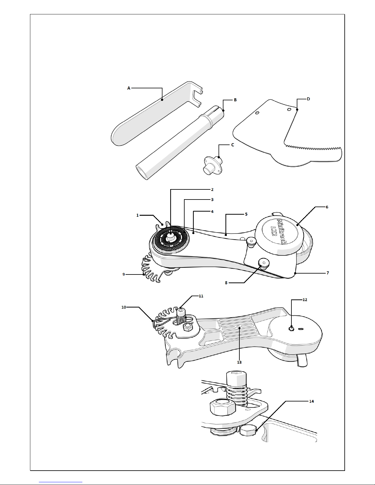
1. What’s included?
A- Adapter Key;
B- Polar finder;
C- ¼” to ¼” adapter;
D- South arm
(unmounted) and
shown as #7
component Side A
(below).
2. MiniTack’s
features.
We recommend knowing
the different MiniTrack’s
LX2 NS features.
Side A components:
1- Polar finder holder;
2- Ball-head adapter;
3- Platform;
4- Arm;
5- Body;
6- Winding-knob;
7- South arm;
8- Thumbnut (two);
9- Spring retainer.
Side B components:
10- Spring;
11- Spring post;
12- Timer screw with
washer;
13- ¼”thread for tripod;
14- Spring blocker.
Page 3
Any form of reproduction of the entire contents of this document or parts thereof beyond the private use is strictly prohibited. Subject to alterations and errors.
All texts, illustrations and symbols are the property of nimax GmbH.
57993_1_EN_Instruction Manual_REV_A 3 / 12
3. How does the MiniTrack LX2 NS mount work? The MiniTrack LX2 NS “follows” i.e. tracks the apparent movement of the
night sky. The NS stands for Northern and Southern Hemisphere as the mount is capable of tracking the sky on both earth’s
hemispheres. The sky “rotates” roughly around Polaris – the northern Star – in the northern hemisphere and around the
South Celestial Pole (or SCP) in the southern hemisphere. In order to successfully track, the mount must point either to
Polaris or to the SCP. This is called setting the mount in station. The mount sits on a tripod head allowing a certain degree
of inclination. Usually the inclination corresponds to the latitude of the user’s location. Besides that, a ball head is required
so that the camera can be easily pointed to the desired object. Then wind-up the built-in timer and you are ready to go!
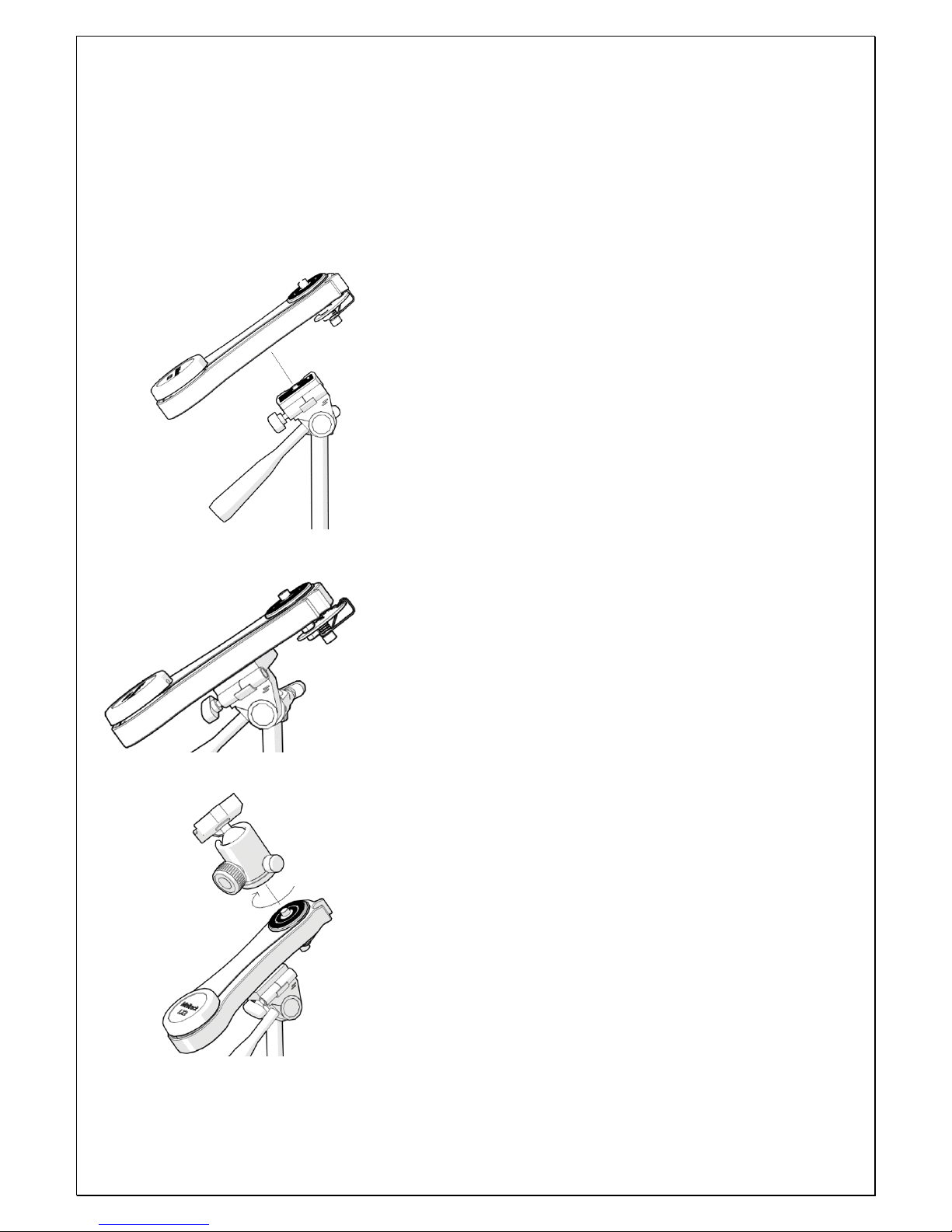
4. How to mount the MiniTrack LX2 NS?
4.1. The MiniTrack LX2 NS is compatible with any ¼” tripod plate (#9 Side B). Set
the mount to the tripod’s plate (not supplied) as shown. Make sure that the
mounts set so the inclination can be adjusted.
4.2. Make sure the mount is parallel to the adapter base. This is important
because the inclination needs to be fine-tuned to set the mount in station.
4.3. We recomend using a ball-head to operate the MiniTrack LX2 NS. It already has
a pre-installed 3/8” thread adapter (factory assembled). If you already have a 3/8”
ball-head and wish to use it just thread it to the adapter (#2 Side A). You can also
use ¼”-20 ball-heads. For that you need to remove the pre-installed 3/8” ball-head
adapter and replace it by the ¼”-20 adapter (C). Use the supplied adapter key (A).
Page 4
Any form of reproduction of the entire contents of this document or parts thereof beyond the private use is strictly prohibited. Subject to alterations and errors.
All texts, illustrations and symbols are the property of nimax GmbH.
57993_1_EN_Instruction Manual_REV_A 4 / 12
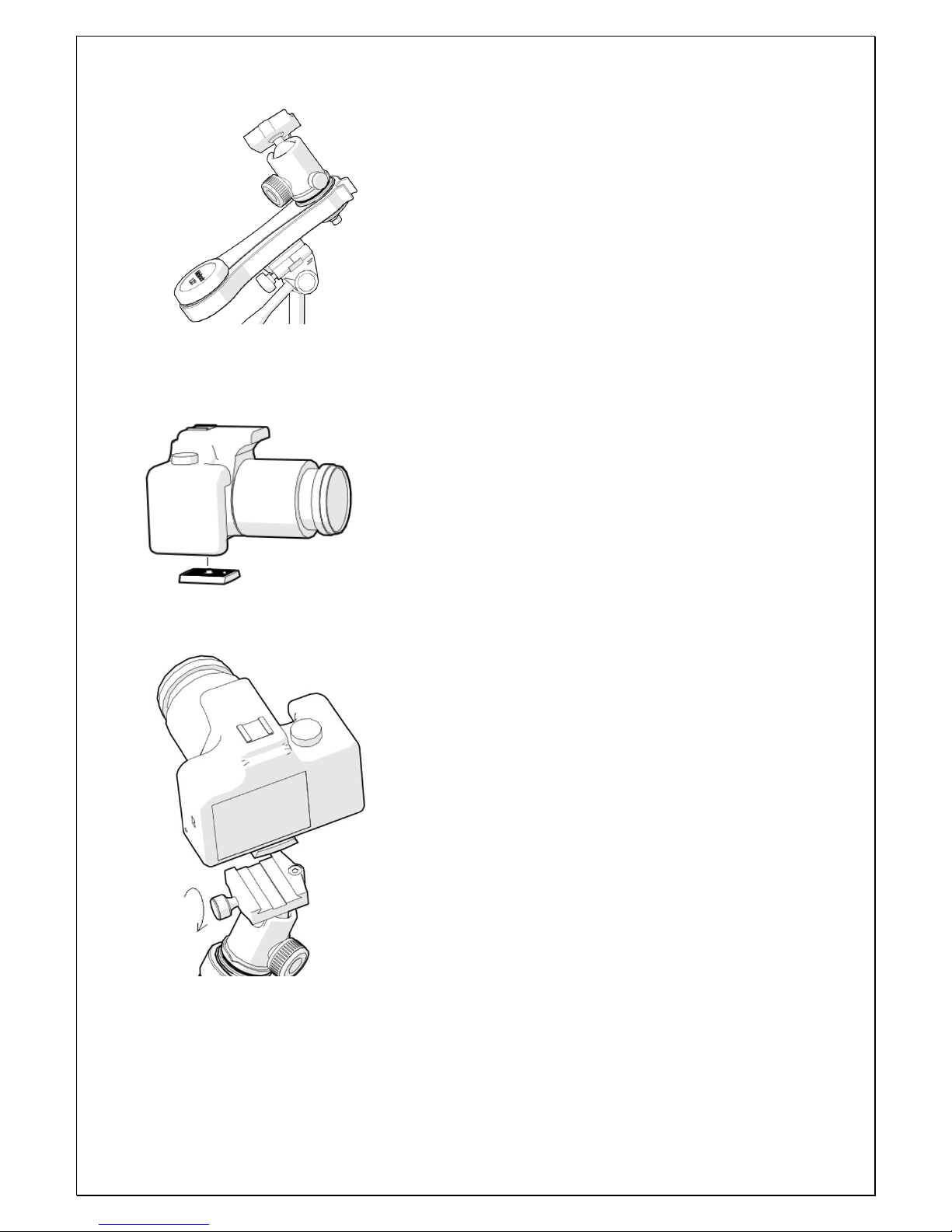
4.4. The ball-head must be securely fixed. Make sure to tighten it well. All the
weight from the camera will rest on the ball-head. Besides that, a well-fixed
ball-head ensures that there will be no slippage during long-exposures. At this
point, it is important that the ball-head knobs are also tight. This prevents
movement when installing the camera.
4.5. Install the tripod plate (included only with the ball-head version) to the
camera. Make sure the adapter is square to the camera base and well tighten.
4.6. Set the camera (with the adapter) to the ball’s-head base. Make sure to
tighten it well. Please notice that the ball-head has two additional knobs. One
fixes the ball’s-head position in azimuth (360 deg) while the other fixes the
ball’s-head pointing direction (in altitude). These two degrees of orientation
allows the user to point to any desired object in the sky. Make sure both are
well tighten before installing the camera. Release the knobs – just slightly – to
allow pointing the camera to different directions.
Page 5

Any form of reproduction of the entire contents of this document or parts thereof beyond the private use is strictly prohibited. Subject to alterations and errors.
All texts, illustrations and symbols are the property of nimax GmbH.
57993_1_EN_Instruction Manual_REV_A 5 / 12
5. Northern hemisphere configuration
5.1. Alignment with Polaris
Point the mount to the Polaris. It is not important to be
exactly aligned with the Polaris– a rough alignment is fine.
Upon installing the supplied polar finder (B) we will look in
more detail on how to have the star in the centre of the polar
finder (B) field of view.
5.2. To align the mount to Polaris with more precision slide the polar finder (B)
to the polar finder holder (#1 Side A).
5.3. Peek through the polar finder (B) and centre Polaris in the visual field.
Turn the tripod’s fine-adjustment levelers to do so. Please read the following
section for more details on how to correctly use the MiniTrack LX2 NS and
the importance of correct balance.
How to identify Polaris?
Polaris is not the brightest star on the sky but still easy to identify. Look up
to north and try to find the Big Dipper (constellation). This is a very
recognisable constellation. Polaris is about six times the distance and
direction of two of it’s brightest stars – Merak and Duhbe.
Page 6

Any form of reproduction of the entire contents of this document or parts thereof beyond the private use is strictly prohibited. Subject to alterations and errors.
All texts, illustrations and symbols are the property of nimax GmbH.
57993_1_EN_Instruction Manual_REV_A 6 / 12
6. Balancing the MiniTrack LX 2
NS on the East hemisphere
(applies only for Northern
hemisphere configuration). The
built-in timer pushes the photo
setup to track the night sky. If the
setup’s centre of mass is slightly
off to the West side of the
hemisphere, the generated armmoment helps the timer to track
the objects, this is good.
However, the opposite, i.e. if the
setup is more off-balanced to
east side it may happen that the
timer will have difficulties to push
and track conveniently. For that reason the built-in spring system acts as a counterweight and gives an extra help to the
timer by adding additional push force.
6.1. Tensioning the spring.
For setups, slightly off-balance use the first positions as shown (image above). You can feel that the spring is not under a lot
of tension. Use the spring at its highest tension only for heavy setups and strong unbalance. See below how to choose the
spring’s position.
Please avoid unnecessary spring tension as this might alter the timer’s clock tracking rate!
6.2. Pointing East. When the
weight of the camera setup tends
to rotate the ball-head in an anticlockwise direction, the spring
should be tensioned to one of the
numbered teeth, based on how
strong the imbalance is. By
tensioning the spring in position 5
(worst case scenario) a weight of
up to 2kg can be balanced – i.e.
pointing to the Zenith
with the camera body towards the
east in respect to the ball-head.
6.3. Pointing South. The spring can be completely disengaged (position “0”) or let it work at idle (position”1”).
6.4. Pointing West. Aiming towards West, especially if there is a strong imbalance, it could happen that the timer
“accelerates” because of the load in favour of the movement, for which the “R” tooth has been added, which allows to
compensate also this unbalancing type, by braking the rotation motion (last figure on the right – top).
How to determine if the timer is not able to push the setup?
Listen to the timer ticking without any load. Compare that sound to when the setup is assembled. Is there a huge sound
difference? – i.e. the timer is not as loud as it should be – then the spring tension must be adjusted.
Page 7

Any form of reproduction of the entire contents of this document or parts thereof beyond the private use is strictly prohibited. Subject to alterations and errors.
All texts, illustrations and symbols are the property of nimax GmbH.
57993_1_EN_Instruction Manual_REV_A 7 / 12
7. Southern Hemisphere configuration
The south hemisphere configuration is to be used below
the equator. In the southern hemisphere, the sky
“rotates” on the opposite direction, i.e. from West to East.
For that reason, it is necessary to add an additional arm
(D) to the mount and invert the sense of the timer’s
movement.
7.1. Release and remove the two thumbnuts (#8 Side A).
7.2. Release and unscrew the timer screw with washer
(#12 Side B) using a Philips-style screwdriver (not
included).
Page 8

Any form of reproduction of the entire contents of this document or parts thereof beyond the private use is strictly prohibited. Subject to alterations and errors.
All texts, illustrations and symbols are the property of nimax GmbH.
57993_1_EN_Instruction Manual_REV_A 8 / 12
7.3. Push the winding knob (#6 Side A) away from the
arm (#4 Side A) in order slide the arm to the left –
please push it slightly only and make sure the spring
(#10 Side B) is not impeding this movement.
7.4. Remove the winding knob (#6 Side A) and the
timer screw and washer (#12 Side B) as shown.
7.5. Turn the winding knob (#6 Side A) 180 degrees
form it’s original position(up-side down) and screw
back the timer screw and washer (#12 Side B) but do
not tighten it yet!
7.6. Place the South arm (#7 Side A) and adjust it to
the arm (#4 Side A) so the it is placed between the
winding knob and the timer. Make also sure that the
two protruding studs and the arm’s thru holes are
aligned. The Winding knob should move freely and be
easily adjustable to the South arm’s teeth.
Page 9

Any form of reproduction of the entire contents of this document or parts thereof beyond the private use is strictly prohibited. Subject to alterations and errors.
All texts, illustrations and symbols are the property of nimax GmbH.
57993_1_EN_Instruction Manual_REV_A 9 / 12
7.7. Push the assembled arm back to it’s original
position. Make sure to keep the winding knob remains
“up-side down”.
7.8. Push the arm to the timer and the winding knob
against the teeth. Use a Philips-style screwdriver (not
supplied) to fix it in place. It is important to not
overtighten the screw as it may damage the timer and
its performance.
8. Adjust the spring post (#11 Side B) to
the south position.
There are two possible spring post
positions each used respectively for the
Northern and Southern configuration. As
mentioned before the mount is already
prepared, out of the box for use in the
northern Hemisphere configuration. In
order to use it south of the equator, i.e. in
the southern hemisphere the spring post
needs to be moved to the south position.
Page 10

Any form of reproduction of the entire contents of this document or parts thereof beyond the private use is strictly prohibited. Subject to alterations and errors.
All texts, illustrations and symbols are the property of nimax GmbH.
57993_1_EN_Instruction Manual_REV_A 10 / 12
8.1. Release and Remove the post using an 4mm Allenkey (not included).
8.2. Move and align the Spring to the adjacent position.
Insert the Spring post and re-tighten it with the Allenkey (not included). Exert caution, do not overtighten it.
9. Balancing the MiniTrack LX 2 NS on the
West hemisphere (applies to the southern
hemisphere configuration only). The built-
in timer pushes the photo setup to track the
night sky. If the setup’s centre of mass is
slightly off to the East side of the
hemisphere, the generated arm-moment
helps the timer to track the objects, this is
good. However, the opposite, i.e. if the
setup is more off-balanced to west side it
may happen that the timer will have
difficulties to push and track conveniently.
For that reason the built-in spring system
acts as a counterweight and gives an extra
help to the timer by adding additional push force.
Important!
When installing the Spring to the south position please make sure to keep the spring’s tip
trapped in-between the spring blocker (#14 Side B) and the main axis. Only this way can the
spring work correctly and add the necessary tension.
Page 11

Any form of reproduction of the entire contents of this document or parts thereof beyond the private use is strictly prohibited. Subject to alterations and errors.
All texts, illustrations and symbols are the property of nimax GmbH.
57993_1_EN_Instruction Manual_REV_A 11 / 12
9.1. Tensioning the spring.
For setups, slightly off-balance use the first positions as shown (image to the left). You can feel that the spring is not under
a lot of tension. Use the spring at its highest tension only for heavy setups and strong unbalance. See below how to choose
the spring’s position.
Please avoid unnecessary spring tension as this might alter the timer’s clock tracking rate!
9.2. Pointing West. When the
weight of the camera setup tends
to rotate the ball-head in a
clockwise direction, the spring
should be tensioned to one of the
numbered teeth, based on how
strong the imbalance is. By
tensioning the spring in position 5
(worst case scenario) a weight of
up to 2kg can be balanced – i.e.
pointing to the Zenith
with the camera body towards
the west in respect to the ballhead.
9.3. Pointing North. The spring can be completely disengaged (position “0”) or let it work at idle (position”1”).
9.4. Pointing West. Aiming towards West, especially if there is a strong imbalance, it could happen that the timer
“accelerates” because of the load in favour of the movement, for which the “R” tooth has been added, which allows to
compensate also this unbalancing type, by braking the rotation motion (last figure on the right – top).
10. Aiming to South Celestial Pole (SCP)
10.1. Identify the Crux constellation near the SCP. Align the stars as shown in the figure and count 4.5x it’s distance in the
same direction to find the SCP. Upon installing the supplied polar finder (B) we will look in more detail on how to have the
star in the centre of the polar finder (B) field of view.
How to determine if the timer is not able to push the setup?
Listen to the timer ticking without any load. Compare that sound to when the setup is assembled. Is there a huge sound
difference? – i.e. the timer is not as loud as it should be – then the spring tension must be adjusted.
How to identify Crux?
Crux is a constellation with the shape of a kite. If align the head and the
tail of the kite an count 4.5x to the tail you get a rough position of the
south celestial pole (SCP).
Page 12

Any form of reproduction of the entire contents of this document or parts thereof beyond the private use is strictly prohibited. Subject to alterations and errors.
All texts, illustrations and symbols are the property of nimax GmbH.
57993_1_EN_Instruction Manual_REV_A 12 / 12
10.2. To align the mount to the SCP with more precision slide the polar finder (B)
to the polar finder holder (1 Side A).
10.3. Peek through the polar finder (B) and
check if the polar finder is pointing to the
region of the sky as shown before. Turn
the tripod’s fine-adjustment levelers to
adjust if necessary. Please read the
sections on how to correctly use the
MiniTrack LX 2 NS and the importance of
correct balance before using the mount.
11. Calculating maximum tracking time. The MiniTrack LX2 NS is designed to carry setups up to 2 kg and track during
60min. This is important to know because setups exceeding this limit may considerably reduce the tracking quality and
total tracking time. Something to notice is the objective’s focal length. Wide-field objectives (low focal length) allow for
more exposure time. Rule of thumb: one can calculate the tracking time without star trailing by using the following
formula:
Time (min) = 100 / Objective focal length (mm)
11.1. Example.
Camera + objective = 1.8 kg; Objective’s focal length 50mm.
This is within the specifications of the mount. We should expect to achieve 100 / 50mm = 2 minutes of tracking without
any problems.
What if the weight exceeds the carrying capacity or if we use more exposure time than the recommended?
Then we will see some star trailing becoming more evident. It may be necessary to try different exposure times to better
judge which one better fit each setup.
12. Resources. For more information please refer to on-line content such as videos. There is also a very active facebook
group (in Italian) about the MiniTrack LX with hundreds of followers and many contributions. The inventor, Mr. Cristian
Fattinnanzi is also a member of this group and would gladly give some information and tips on how to use this mount.
Main language is however Italian.
13. Features.
Carrying capactity: 2 kg
Balancing: using spring system (no counterweight)
accepts ball heads with ¼” or 3/8” photo thread.
Ball-head weight: 300g
MiniTrack LX2 weight: 430g
Total tracking time: 60 min
Polar finder: included
Hemisphere: northern and southern (NS version)
Objective focal length
Maximum recommended exposure
24mm
4 minutes 10sec
50mm
2 minutes
60mm
1min 40sec
100mm
1 min
 Loading...