

Instructions Manual
Omegon® AC 70/400 BackPack AZ
English version 3.2017 Rev A Art-Nr. 53090
The Omegon® AC 70/400 BackPack AZ
Congratulations on the purchase of the new Omegon® AC 70/400 BackPack AZ. This telescope will
give you hours of fun, with its optical glass lens and light gathering capability it is the ideal
companion to start in the world of terrestrial view and the night sky. With this telescope, you will be
able to see the craters on the Moon, Sun Spots (with the supplier Sun filter), the Galilean Moons and
the rings of Saturn.
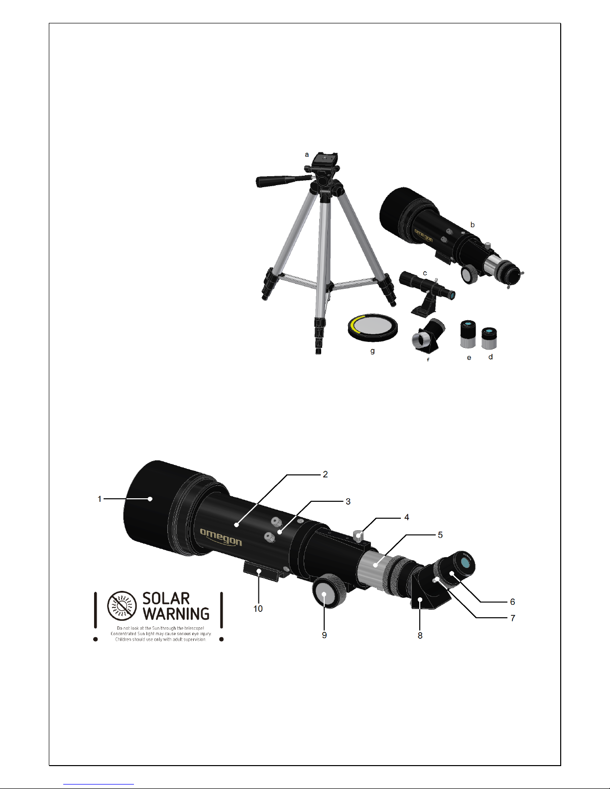
Included parts.
a - Aluminium Tripod;
b- Optical tube;
c- 5x finderscope;
d- K20mm eyepiece 1.25”;
e - K10mmr eyepiece 1.25”
f - Prism 1.25”;
g - Sun filter;
h – Back pack (not shown)
1. Knowing your telescope.
1.1. The Optical Tube (b)
The optical tube is one of the two
main parts of the telescope. It has a
glass lens (objective) - (1) at one
end. The objective gathers light from objects. This telescope has a 70mm (2.7”) objective, this is the
lens diameter. On the opposite end of the objective there is the focuser (9). The focuser is a
mechanical system that extends a tube #5. It allows in combination with the prism (8) and one of the
two eyepieces K20mm (e) and K10mm (d) (included) to obtain a magnified image that can be
observed peeking through the eyepiece lens. The optical tube also carries a small telescope finderscope - (c) which is used to aim the optical tube to an object to be observed. A tripod is
required to point and a Sun filter can be used to observe the Sun.
1- Objective lens 2- Optical tube 3- Finderscope base
4- Brake (focuser) 5- Draw-tube 6- Eyepiece
7- Prism thumbscrew 8- Prism 9- Knob (focuser)
10- Dovetail
Figure 2. Optical Tube.
Figure 1. What’s included.
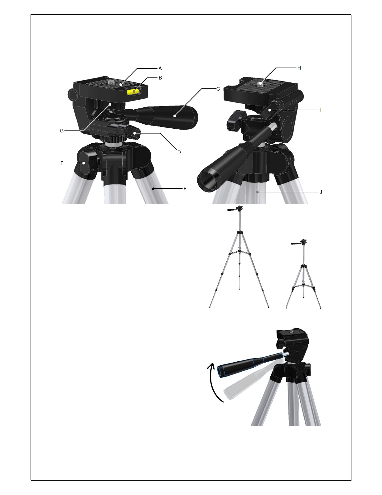
1.2. The tripod (a). The supplied aluminium tripod is used as a platform to place the optical tube.
Here are some details about the tripod’s head – figure 3.
A- Telescope base; B- Bubble level;
C- Hand Grip; D- Lock-az;
E- Tripod Leg; F- Lock (shaft);
G- Lock (telescope); H- ¼”-20 Camera thread;
I- Lock (tilt); J- Shaft.
1.2.1. Extending the tripod. The tripod is compact
and the metal legs can be extended into several
configurations. A central shaft allows additional
extension if required – figure 4.
The most stable configuration is, however, with the
tripod’s legs collapsed to their minimum. It’s
recommend using the collapsed tripod on a table top
for more comfort and stability.
1.2.2. Camera base (A). The tripod’s camera base (A)
is compatible with most photo and video cameras
having a ¼”-20 thread standard. It also allows to level
horizontally by using the integrated bubble level (B).
1.2.3. The hand grip (C). Is used to direct and point
the tripod to a certain direction it also acts as a brake
to fix the tripod to a certain tilt. Release to tilt the
camera base (A) – figure 5.
1.2.4. Rotating the tripod head in az. Release the
Lock-az (D). One can see that the tripod head now
rotates freely around the tripod’s shaft (J) – azimuth
movement. Tighten to lock in a specific azimuth
direction – figure 6.
Figure 3.
Figure 4.
Figure 5.
 Loading...