

Page 1
1
Instruction Manual
Omegon AC 50/500 AZ
English version 2.2015 Rev A
Page 2
2
The Omegon® AC 50/500 AZ
Congratulations on the purchase of the new Omegon® AC 50/500 AZ. This small telescope will give
you hours of fun. With this telescope, you will be able to see the craters on the Moon and much
more.
1. Included parts.
We have included
several accessories, which will make the use of the telescope easier and fun. Please take a look at
the list of the parts, so you can identify them in the future.
1. & 2. Two eyepieces 0.965” (24.5mm); an H20mm and an H12.5mm eyepiece;
3. 14x microscope/erecting eyepiece;
4. 6x finderscope;
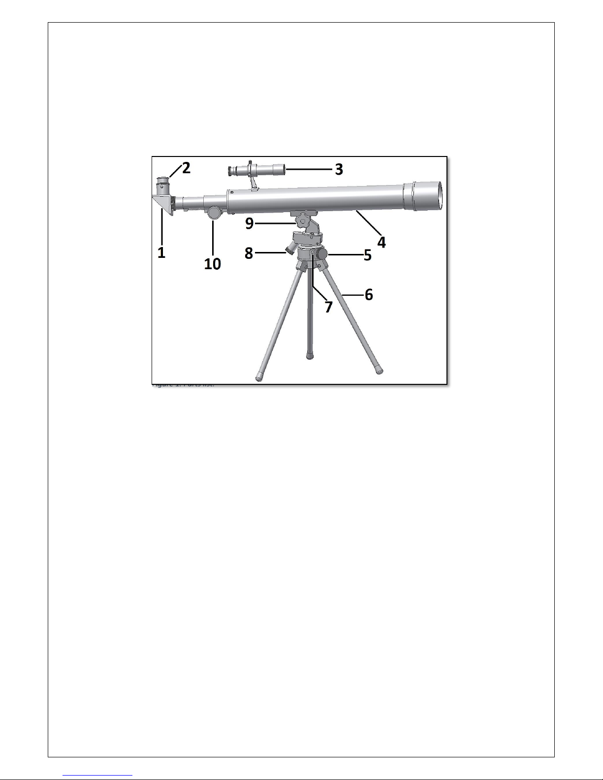
2. Parts list description.
1- Diagonal mirror; 6- Tripod leg;
2- Eyepiece; 7- Azimuth locking thumbscrew;
3- Finderscope; 8- Altitude adjustment;
4- Optical tube; 9- Fixing knob;
5- Azimuth adjustment; 10- Focuser.
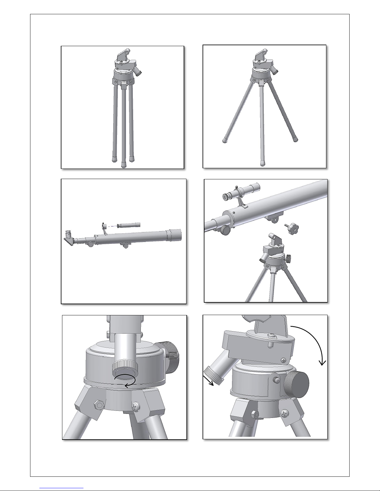
3. Getting started.
Extend the tripod as shown in figure 3. Insert the finderscope in bracket as shown in figure 4. Use
the three finderscope screws to fix the finderscope tube. Place the tube on the tripod (figure 5). Use
the supplied fixing knob to secure the tube. The mount has two precision adjustments: an altitude
(figure 6) and an azimuth adjustment. When the altitude adjustment is rotated, the mount tilts in
altitude (figure 7). The azimuth adjustment allows adjusting the mount in azimuth (figure 8). Both
adjustments are used when pointing to an object to precisely center it in the field of view. To lock
the azimuth adjustment, use the fixing knob (figure 9). It is important to align the finderscope with
the telescope, so whenever you point the telescope, the image seen through the finderscope
matches the one in the telescope’s eyepiece. Additional instructions on how to align the
finderscope can be found on the next pages.
Figure 1. Parts list.
Page 3
3
Figure 2. Tripod assembly.
Figure 3. Extended tripod..
Figure 4. Insert finderscope.
Figure 5. Place the tube and fix it.
Figure 6. Altitude adjustment.
Figure 7. Tilt the mount by turning the altitude adjustment.
Page 4

4
3. Start using your Omegon® AC 50/500 AZ telescope. Place both the diagonal mirror and the
eyepiece in the focuser tube and use the existing thumbscrews to fix it. Now point the telescope to a
distant object during the day. It is important to do this during daylight, so that you get familiarized
with the telescope operation. A good target is a church tower, a chimney or a distant mountain
peak. Rotate the focuser knob, so that the focuser tube moves in and out. Do this slowly. We suggest
that you start by racking the focuser all the way in and slowly move it out. With the 20mm eyepiece
you should be able to get a focused image easily. 3.1. The Finderscope. Before, we mentioned the
finderscope as a valuable tool to point the telescope to an object. To operate properly, the telescope
and the finderscope should be aligned. The image obtained through the finderscope has a much
broader field of view than that of the telescope. Please take a look on how the finderscope works on
the next pages.
Figure 8. Turning the azimuth adjustment.
Figure 9. Azimuth locking knob.
Figure 10. Adjusting the finderscope.
Figure 11. Microscope/erecting eyepiece.
Page 5

5
4. How to use and how to align the finderscope?
4.1. A distant object is centered at the
telescope’s field of view with an eyepiece. In this
example we have a house with a chimney. The
chimney is the reference point to place at the
center of the field of view. We first look through
the telescope with the lowest magnification
possible, so we have the widest field of view.
4.2. When looking through the finderscope we
see the same building, but in this case the
chimney is not centered. We adjust the
finderscope using the three thumbscrews, so that
the finderscope moves slightly. This is enough to
correct the objects position in the finderscope.
Trial and error is required to get a satisfactory
result. Make sure to tighten the 3 screws after
finishing, so that the finderscope tube does not
move.
4.3. After playing with the three findercope
thumbscrews and some trial and error, we get
the finderscope’s recticle close to the center (in
this case the chimney). The finderscope is now
ready to use!
Page 6

6
5. Using the accessories: a bit of math to
understand how it all works.
Using the accessories is easy and fun. To
change magnification simply swap eyepieces.
To get more magnification simply use the
barlow lens. But how does all of this work?
5.1. Power (magnification)
Your telescope has a focal length of 500mm.
This is approximately the distance between
the telescope lens and its focal point (very
similar to the distance between the focus
point of a loupe and the loupe lens). This is a
very important feature, that allows to
determine several interesting facts such as
magnification.
The magnification is determined by the
telescope’s focal length and the used
eyepiece. You probably noticed that the two
supplied eyepieces are 20mm and 12.5mm.
This means that the 20mm is a 20mm focal
length eyepiece while the 10mm is a 10mm
focal length eyepiece.
To determine the magnification, just divide
the telescope’s focal length by the eyepiece’s
focal length. Let’s give an example for our
telescope and the supplied eyepieces:
Telescope’s focal length is 500mm.
20mm eyepiece’s focal length is 20mm.
500𝑚𝑚
20𝑚𝑚
= 25 𝑝𝑜𝑤𝑒𝑟
This means that the 20mm eyepiece provides
a 25x power (magnification). This seems low,
but when you try it, you will see a bright
image with some (very good) details.
5.2. Barlow Lens (not included)
The barlow lens is a very interesting device. It
is a negative lens, that multiplies the
telescope’s focal length. So a 2x Barlow
multiplies the original focal length by 2x, in
this case 500𝑚𝑚 𝑥 2 = 1000𝑚𝑚.
A 3x Barlow lens multiplies by 3x.
Your telescope is supplied with a 2x Barlow
lens. When used with the 20mm eyepiece you
get 2x the power obtained before
25 𝑝𝑜𝑤𝑒𝑟 𝑋 2𝑥 𝐵𝑎𝑟𝑙𝑜𝑤 = 50 𝑝𝑜𝑤𝑒𝑟
5.3. Erecting lens
The erecting lens gets you an upright image
view with the telescope. It also adds some
power like the barlow lens. The erecting lens
provides an extra 1.5x power.
5.4. Diagonal Mirror
This diverts the light coming from the
telescope to an angle of 90 degrees. It is
useful, because it provides a more
comfortable position when observing.
Here are some examples on how to use the
accessories.
Some possible accessory combinations
Terrestrial
View
Moon
20mm Eyepiece
Yes
12.5mm Eyepiece
Yes
Power
25x
50x
Page 7

7
6. What can be seen with this telescope?
Below, you will find some examples of what you can
expect to see when using this telescope.
6.1. The Moon is one of the most spectacular
objects to be seen through a telescope. Even a small
telescope will reveal high detail of the Moon’s
surface. You will be able to see the craters on the
Moon’s surface and other features like the Marea.
The Moon is a very bright object. It is better to
observe it when the Moon is not full. Try the
crescent Moon and look for features along the
terminator (between illuminated and dark surfaces).
6.2. Jupiter is the biggest planet of our solar system.
It is also one of the favorite targets for beginners.
Galileo was able to discover that the four tiny dots
that circle around the planet were in fact part of
Jupiter’s system of moons. With this telescope, you
will not only be able to see Jupiter’s planet disc with
its two major discernible bands, but also its biggest
moons, Io, Europa, Ganymedes and Callisto.
6.3. The “lord of the rings” of the night sky, Saturn,
is by far the most popular target for small
telescopes. Saturn’s rings are discernible even at
60x magnification. In a very good night you will be
able to see the Cassini’s division (the darker band of
Saturn’s rings).
Page 8

8
7. Troubleshooting and frequently asked questions
Q: I get a mirrored view of the objects. Like if they were reversed, and R shows up like ᴙ.
R: This is caused by the telescope’s mirrors. To get a corrected image it is necessary to use the
correcting lens and the eyepiece as shown below.
Q: I use the finderscope to point to objects, but I always miss the target.
A: You probably need to realign the finderscope. Please proceed as described in 4.2.
Q: Is my telescope compatible with other eyepieces ?
A: Omegon telescopes are compatible with all telescope eyepieces from different manufacturers as
long as the eyepiece is a 0.965” (or 24.5mm) size eyepiece. If you would like to test an eyepiece from
a fellow astronomer go ahead. Different eyepieces provide different visual experiences.
Q: I want to use my telescope to take pictures.
A: This telescope is designed for visual use only.
Q: The stars only appear as points in the telescope.
A: Stars will always only appear as points, even in the largest telescopes in the world. It is more
interesting for beginners to observe two-dimensional objects, such as the Moon or planets. Once you
find these, you will be able to start learning about the astronomical calendar.
Q: I would like to observe the Sun.
A: We do not recommend that you observe the Sun with this telescope. It is extremely dangerous to
point a telescope to the Sun. Children should always be supervised when using the telescope during
day-time.
Q: I can’t see anything, when I look through my telescope.
A: The dust caps must first be removed and an eyepiece inserted before you can start observing. Are
you sure you have removed all the dust caps, not just the small one? If you have not, then no light
will enter the telescope and everything will appear black.
8. How to use the supplied Microscope/Erecting eyepiece
The erecting eyepiece can replace the diagonal and
the eyepiece. Remove the diagonal and eyepiece
and place the Microscope/Erecting eyepiece. Fix it
using the existing thumbscrew. When looking
through it, you will get an upright image. It is
interesting for terrestrial viewing.
The Microscope/Erecting eyepiece can also be used
as a hand-microscope. Place the microscope base
on an object you would like to observe (like a plant
leaf) and peak through the eyepiece.
Questions? Visit our website www.astroshop.eu and drop us a line* nimax Gmbh Otto-Lilienthal-Str. 9 D-86899 Landsberg am Lech
 Loading...