

Page 1
1
Instruction Manual
Omegon® 150/750 EQ-4
English version 12.2014 Rev A
Page 2
2
The Omegon® 150/750 EQ-4
Congratulations on the purchase of the new Omegon® 150/750 EQ-4. This advanced telescope will
give you hours of fun, with its all optical glass lens and light gathering ability, it is the ideal
companion for deep sky observation. With this telescope you will be able to see the craters on the
Moon, star clusters, nebulae the Jupiter disc features and its Galilean moons and the rings of Saturn.
We have included many accessories so it will be easy to use this telescope.
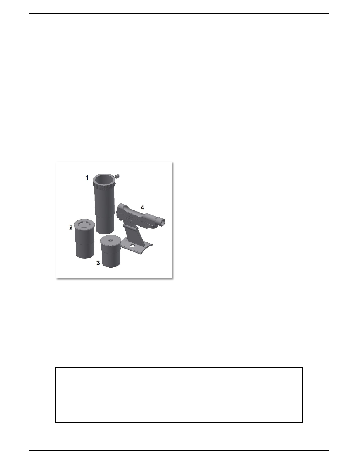
1. Included parts
We have included several accessories that will make the use of the telescope easier and fun, please
take a look at the list of the parts so you can identify them in the future.
1. Barlow Lens 2x.
2, 3. Two eyepieces 1.25” (31.75mm); a Plössl 25mm, Plössl 6.5mm eyepiece;
4. Red-dot Finderscope;
2. Getting Started
It is very simple to get started. Here is how the
telescope works. The telescope main lens should
point to the object being observed. The mirror
on the back of the tube will gather the light
coming from the object and reflects it to the
secondary mirror that brings it to the eyepiece.
The focuser tube moves up and down to get a
precise focused image. At the focuser one can
use the supplied accessories. Different accessory
combinations give different results, such as
different image magnifications or correct image.
But all this will be explained in detail in the next
pages.
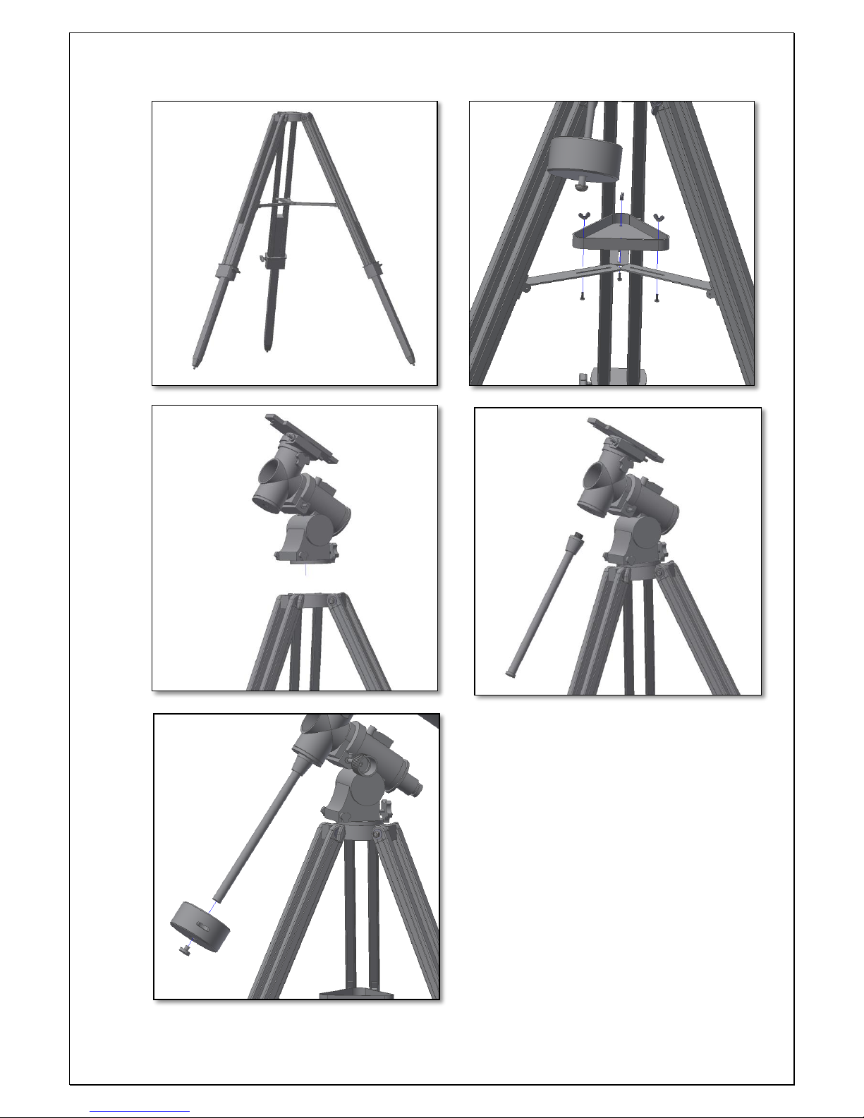
3. Assembly
Start by setting the tripod. Open the tripod legs as shown (figure 2). Place the supplied accessory
tray (figure 3). The accessory tray can be used to place the telescope accessories such as the
eyepieces, filters etc. Next place the equatorial mount on top of the tripod (figure 4), the mount will
bear all the weight of the telescope so it is important to thread it securely. Thread the counterweight
shaft as shown (figure 5), it fits the threaded hole on the Right Ascension (R.A.) axis. Remove the
foot-saver (the screw and washer – figure 6) from the shaft’s end and slide in a Counterweight. Make
sure to use the counterweight’s locking knob so that it is securely fastened. You can leave it at half
the shaft length for now.
ATTENTION! Never look at the Sun through a
telescope. Concentrated Sun light may cause serious
eye injury. Children should use only with adult
supervision.
Figure 1. Parts List
Page 3
3
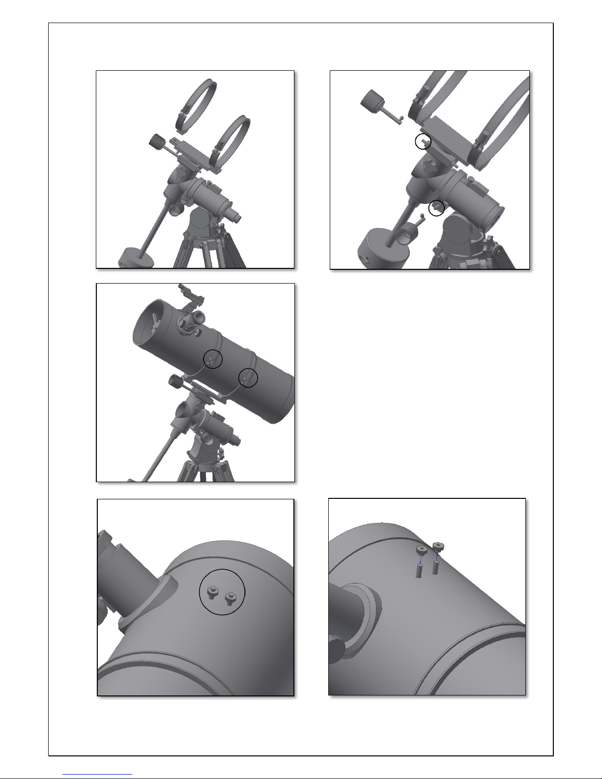
Place the tube rings (figure 7) on the mount
platform and make sure both clamp knobs
are facing the same side, they will be used to
place and remove the optical tube when
necessary. It is important that they are well
tightened and don’t rotate. Next, insert the
fine adjustment knobs on each axis (figure
8). These knobs allow to make small
movements on both axis of the telescope.
Use the included thumbscrew on each. Make
sure they fit the slotted surface on the
protruding axis shaft. Open the tube rings
that were previously fitted to the telescope
and insert the tube (figure 9). Close the
Figure 3. Tray placement.
Figure 2. Set the tripod.
Figure 5. Thread the counterweight shaft.
Figure 4. Place the equatorial mount.
Figure 6. Slide counterweight and thread the foot-saver.
Page 4
4
rings and clamp the two knobs. Slide the tube
so that the focuser is pointing up and is more or
less centred. Depending on the telescope tube
weight you might find useful to use two
counterweights. The finderscope is placed next
to the focuser, remove the two thumbscrews as
shown in figure 11 and place the finderscope.
Make sure the finderscope (figure 12) is
pointing in the same direction as the
telescope’s aperture so when you point the
telescope to an object you also point the
finderscope to it.
Figure 7. Place the tube rings.
Figure 8. Place fine adjustment knobs.
Figure 9. Slide tube and thread the ring knobs.
Figure 10. Finderscope thumbscrews.
Figure 11. Remove the finderscope thumbscrews.
Page 5

5
Note the two locking handknobs (fgure 13).
When released they work as clutches and allow
free movement in both axis. When fully
tightened you can use the fine adjustment knobs
(figure 8). For easy operation the telescope still
needs to be balanced. Adjust the counterweights
(figure 14) so that when you release the locking
handknobs the telescope moves freely. The
telescope is balanced when neither the tube nor
the shaft axis tilt to any side. To adjust the R.A.
axis (arrow in figure 15) and rotate the altitude
handknob (circle in figure 15). When ready lock
again. To adjust the azimuth use the two side
hand knobs as shown in figure 16.
Figure 12. Place finderscope.
Figure 13. Locking handknobs.
Figure 14. Balance the telescope.
Figure 15. Adjust the altitude axis.
Figure 16. Adjust the azimuth axis.
Page 6

6
4. Alignment of the optics and collimation.
Telescopes require periodical checking for the alignment of the optics. The optics should be
aligned (or collimated) so that the telescope can achieve a good performance and deliver a
sharp image. This is especially important for reflector telescopes (that use mirrors). First
let’s start by checking the collimation.
Look for a bright star in the evening sky and centre it in the eyepiece’s field of view. Some
power is required to check alignment, make sure the star is focused. Now use the focuser
knobs and rotate so that the star comes out of focus (defocused). You will be able to see a
defocused star. It will appear as a series of rings. These are called diffraction rings and they
will be important to determine how good (or how bad the alignment is– figure 19). If the
optics are well aligned you will be able to see a defocused
star similar to a series of concentric rings (1 in figure 19), a
poorly aligned telescopes will show a series of eccentric
rings (2 in figure 19).
The telescope is equipped with a set of collimation screws
for both the secondary mirror (figure 17) and for the primary
mirror (figure 18). They can be used to adjust the tilt of both
mirrors and to achieve alignment. This information is for
your reference.
Figure 17. Adjust the secondary mirror.
Figure 18. Adjust the primary mirror.
Figure 19. Diffraction Rings: 1. good
alignment and 2. Poorly aligned
Page 7

7
4.1. Collimate the optics.
Remove the eyepiece from the telescope’s focuser. If you look directly to the secondary
mirror, you will see a reflection of your eye. The light is being reflected from the secondary
mirror to the primary and back.
Figure 20 shows the different stages of
collimation.
1- Telescope optics are completely out of
collimation. Adjustment is necessary both in
the secondary and in the primary mirror.
2- Secondary mirror is aligned but primary
mirror needs adjustments.
3- Telescope´s optics are aligned and star test
should show concentric rings. The telescope
will perform at its best.
4.2. So how to get to good alignment?
4.2.1. Let’s start with the secondary mirror.
When peeking at the focuser without the
eyepiece and looking at the secondary mirror
one can see the reflected eye. One can also
see the telescope secondary spider vanes (4
vanes cross shaped) and the primary mirror’s
holding pads (figure 21).
The secondary mirror can be adjusted by using
the 3 screws (figure 17). Releasing it can make
the secondary mirror support to rotate. So
make sure you only adjust one screw at a time
to avoid it. The secondary mirror should always
show up as a circle and not an ellipse. Please make sure this is the case.
As soon as you get the primary mirror and the primary mirror pads centred (figure 20 – 2)
you are good to go to the next step.
4.2.2. The primary mirror needs to be adjusted. Adjusting
the primary mirror will move the secondary mirror
reflection to the center. Use the 6 screws on the back of
the telescope. Notice that 3 screws are used to adjust the
tilt of the primary mirror while the three others are used
to hold the tilt position. Adjust the primary mirror so that
you get all reflections centred (figure 19 – 3). Your
telescope is now collimated. Check the diffraction rings
(figure 19) and repeat it if necessary.
Figure 20. Different stages of collimation.
Figure 21. Vanes and primary pads.
Page 8

8
4. Start using your Omegon 150/750 EQ-4 telescope. Point the telescope to a distant object
during the day. It is important to do this during daylight so that you get familiarized with the
telescope operation. A good target is a church tower, a chimney or a distant mountain peak. Rotate
the focuser knob so that the focuser tube moves in and out. Do this slowly. We suggest that you
start by racking the focuser all the way in and slowly move it out. With the PLössl 25mm eyepiece
you should be able to get a focused image easily.
Make sure to use the locking hand knobs (figure 13) and use the fine adjustment knobs (figure 8) to
point the telescope to an object.
ATTENTION! Never use the altitude and azimuth knobs to point to the
telescope. The altitude knob bears all telescope weight and continuous use
can damage it permanently!
5. The finderscope. Before we mentioned the finderscope as a valuable tool to point the telescope
at an object. To operate properly, the telescope and the finderscope should be aligned. The image
obtained through the finderscope has a much broader field of view than that of the telescope.
Aligning means matching the telescope image to the image of the center of the finderscope. This
way when looking through the finderscope one knows the telescope is pointing exactly to the same
point, making looking at objects much more easier.
5.2. How to align the finderscope?
You have the house chimney (example mentioned before) centered at the telescope eyepiece field of
view. Now look through the finderscope. The small red dot (recticle) in the center of the finderscope
field of view should match the center of the telescope field of view. Adjust the two finderscope
thumbscrews to get the red point to the same object as the telescope (as shown in figure 5.2.2).
Questions? Please visit our website and drop us a line www.astroshop.de
nimax Gmbh
Otto-Lilienthal Str. 9
D-86899 Landsberg am Lech
Page 9

9
5.2.1. A distant object is centered at the telescope’s field of view. In this example we have a house
with a chimney. The chimney is the reference point
to place at the center of the field of view. We first
look through the telescope with the lowest
magnification possible (PLössl 25mm should be
preferable), so we have the widest field of view.
5.2.2. Looking through the finderscope (it should be
powered on) we see the same building, but in this
case the chimney is not centered. We adjust the
finderscope using the two thumbscrews so that the
finderscope point moves slightly. This is enough to
correct the object’s position in the finderscope. Trial
and error is required to get a satisfactory result.
5.2.3. After playing with the two findercope
thumbscrews and some trial and error, we get the
finderscope recticle close to the center (in this case
the chimney). The finderscope is now ready to use!
Page 10

10
6. Using the accessories, a bit of math to
understand how all it works.
Using the accessories is easy and fun. To
change magnification simply swap eyepieces.
To get more magnification simply use the
barlow lens. But how does all of this work?
6.1. Power (magnification)
Your telescope has a focal length of 750mm.
This is approximately the distance between
the telescope lens and its focal point (very
similar to the distance between the focus
point of a loupe and the loupe lens). This is a
very important feature that allows to
determine several interesting facts such as
magnification.
The magnification is determined by the
telescopes focal length and the used
eyepiece. You probably noticed that the three
supplied eyepieces are Plössl 25mm and Plössl
6.5mm. This means that the Plössl 25mm is a
25mm focal length eyepiece, while the Plössl
6.5m is a 6.5mm focal length eyepiece.
To determine the magnification just divide the
telescope’s focal length by the eyepiece’s
focal length. Lets give an example for our
telescope and the supplied eyepieces:
The Telescope focal length is 750mm
Plössl 25 eyepiece focal length is 25 mm
750𝑚𝑚
25𝑚𝑚
= 30 𝑝𝑜𝑤𝑒𝑟
This means that the Plössl 25mm eyepiece
provides a 30x power (magnification). This
seems low, but try it, you will see a bright
image with a lot of detail.
6.2. Barlow Lens
The Barlow lens is a very interesting device. It
is a negative lens that multiplies the
telescope’s focal length. So a 2x Barlow
multiplies the original focal length by 2x, in
this case 750mm x 2 = 1500mm.
A 3x Barlow lens multiplies it by 3x. Your
telescope is supplied with a 2x Barlow lens.
When used with the PLössl 25mm eyepiece
you get 2x the power obtained before
30 power X 2x Barlow = 60 power
6.3. Erecting lens (not included)
The erecting lens gets you an upright image
view with the telescope. It also adds some
power like the barlow lens.
6.4. Diagonal Mirror (does not apply to
this telescope model)
This diverts the light coming from the
telescope to an angle of 45 or 90 degrees. It is
useful, because it provides a more confortable
position when observing.
Here are some examples on how to use the
accessories.
Some possible accessory combinations
Terrestrial
View
Moon
Deep Sky
Jupiter and
Saturn
Barlow Lens 2x
Yes
PL6.5mm Eyepiece
Yes
PL25mm Eyepiece
Yes
Yes
Power
Not suitable
60x
30x
115x
Page 11

11
6. What can been seen with this telescope?
Below you will find some examples of what you can expect to see when using this telescope.
6.1. The Moon is one of the most spectacular
objects to be seen through a telescope. Even a small
telescope will reveal high detail of the Moon’s
surface. You will be able to see the craters on the
Moon’s surface and other features like the Marea.
The moon is a very bright object. It is better
observed when the Moon is not full. Try the
crescent Moon and look for features along the
terminator (between illumated and dark surfaces).
6.2. Jupiter is the biggest planet of our solar system.
It is also one of the favorite targets for beginners.
Galileo was able to discover that the four tiny dots
that turn around the planet were in fact part of
Jupiter’s system of moons. With this telescope you
will be able to see not only Jupiter’s planet disc with
its two major discernible bands, but also its biggest
moons, Io, Europa, Ganymedes and Callisto.
6.3. The “lord of the rings” of the night skies, Saturn
is by far the most popular target for small
telescopes. Saturn’s rings are discernible even at
60x magnification. In a very good night you will be
able to see the Cassini’s division (the darker band
on the Saturn’s rings).
Page 12

12
7. Troubleshooting and frequently asked questions
Q: I get a mirrored view of the objects. Like if they were reversed, and R show’s up like ᴙ
R: Mirror telescope reverse objectes, this is give a mirrored image of the object. To get a corrected
image it is necessary to an image corrector. Note that reflector telescopes are not intended to be
use for terrestrial observation.
Q: I use the finderscope to point to objects but I always miss the target.
A: You probably need to realign the finderscope. Please proceed as described in 4.2.
Q: When I use the barlow lens and the Plössl 6.5mm eyepiece the image is so dark I can’t hardly
see anything.
A: Power should be used with moderation. It depends on how stable the atmosphere is, too much
turbulence causes image distortion. Usually the limit is 2x for each millimeter of the telescope
aperture. In this case, the telescope has an aperture of 150mm, so in a very good night you should be
able to reach 300x. The more magnified the image is, the darker it gets.
Q: Is my telescope compatible with other eyepieces ?
A: Omegon telescopes are compatible with all telescope eyepieces from different manufacturers as
long as the eyepiece is a 1.25” (or 31.75mm) size eyepiece. If you would like to test an eyepiece from
a fellow astronomer go ahead. Different eyepieces provide different visual experiences.
Q: I want to use my telescope to take pictures.
A: This telescope is designed for visual use. It doesn’t mean it can’t be used for photography, however
it will be hard to get high quality pictures with this telescope. If you have a smartphone you can shoot
the Moon or some terrestrial objects. Search online for digiscoping and afocal photography.
Q: The stars only appear as points in the telescope.
A: Stars will always appear only as points, even in the largest telescopes in the world. It is more
interesting for beginners to observe two-dimensional objects, such the moon or planets. Once you
find these, you will be able to start learning about the astronomical calendar.
Q: I would like to observe the Sun.
A: An appropriate solar filter, placed over the objective, is essential for observing the sun. These are
available as plastic foil or glass filters. They allow only a tiny and harmless fraction of sunlight into
the telescope, when securely positioned over the objective, so allowing you to observe the sun in
complete safety. Eyepiece solar filters (not available from us) should be avoided at all costs as they
are considered unsafe.
Note: Never look directly at the sun through a telescope without an objective solar filter!
Q: I can’t see anything when I look through my telescope
A: The telescope is only suitable for astronomical observing and when used outside at night.
Observing from inside the house or during the day is usually not possible. The dust caps must first be
removed and an eyepiece inserted before you can start observing. Are you sure you have removed all
the dust caps, not just the small ones? If you have not, then no light will enter the telescope and
everything will appear black.
 Loading...