

Page 1
Stepper DriveS
performance Stepper DriveS With
aDvanceD featureS anD control optionS
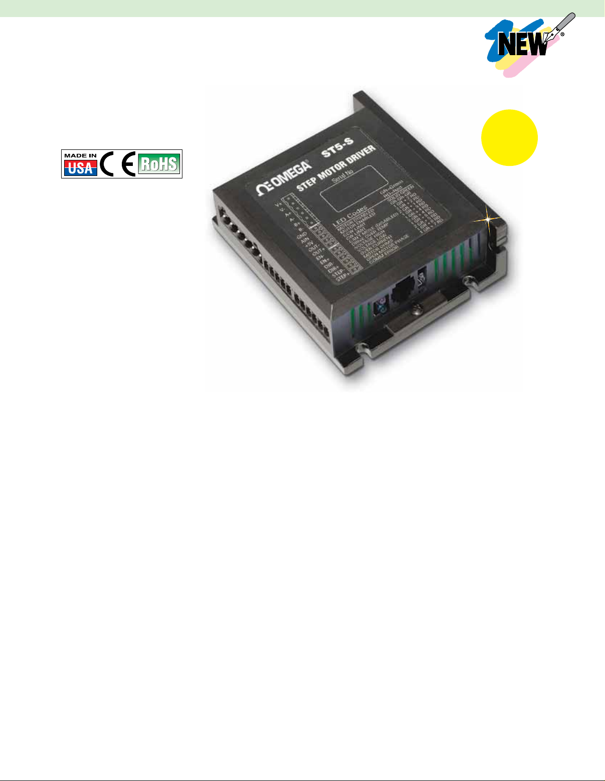
ST Series
l Current Output 0.5 to 10.0 A
l Configurator
Configuration Software
l Configurable Idle
Current Reduction
l External Control Options
l Pulse and Direction
l Analog Command Signal
l Host Command Via RS232/485
l Fault Protection (Over-Voltage,
Under-Voltage, Over-Temp,
External Output Shorts, Internal
Amplifier Shorts)
l Multi-Axis System with
SiNet
TM
l Stand-Alone Programming
on Si Model
l Microstepping Emulation
(Up to 51200 steps/revolution)
Hub
TM
Advanced Features
l Auto Setup: Measures Motor
Parameters and Configures
Tuning Parameters
l Self-Test: Detects Encoder
and Determines Resolution;
Diagnoses Miswires and
Open Phases
l Torque Ripple Smoothing:
Smoother Motion at
Lower Speeds
l Command Signal Smoothing:
Assures Smooth Acceleration/
Deceleration Ramps
l Anti-Resonance: Eliminates
Mid-Range Instability; Allows
Stable Operation to 50 rps
or Greater
SPECIFICATIONS
ST5-S, ST5-Si POWER
AMPLIFIER SECTION
Amplifier Type: MOSFET, Dual
H-Bridge, 4 Quadrant
Current Control: 4 state PWM at 20 KHz
Output Current: 0.5 to 5.0 A/phase in
0.01 A increments
Power Supply: External 24 to 48 Vdc
power supply required
Input Voltage Range: 18 to 53 Vdc
Protection: Over voltage, under voltage,
over-temp, external output shorts
(phase-to-phase, phase-to-ground),
internal amplifier shorts
Idle Current Reduction: Reduction to
any integer percent of full-current after
delay selectable in milliseconds
ST10-S, ST10-Si POWER
AMPLIFIER SECTION
Amplifier Type: MOSFET, Dual
H-Bridge, 4 Quadrant
Current Control: 4 state PWM at 20 KHz
Output Current: 0.5 to 10.0 A/phase in
0.01 A increments
Power Supply: External 24 to 80 Vdc
power supply required
Input Voltage Range: 18 to 88 Vdc
Protection: Over voltage, under voltage,
over-temp, external output shorts
(phase-to-phase, phase-to-ground),
internal amplifier shorts
Configuration
Software
Included!
ST5-S
shown close
to actual size.
Idle Current Reduction: Reduction to
any integer percent of full-current after
delay selectable in milliseconds
-S AND -SI (COMMON FEATURES)
CONTROLLER SECTION
Mode of Operation: Step and direction,
CW/CCW, encoder following, oscillator,
joystick, SCL, Si (Si programming is
only available on the -Si models)
Microstep Resolution: Software
selectable from 200 to 51,200 steps/rev
in increments of 200 steps/rev
Speed Range: Depends upon selected
resolution; amplifier is suitable for
speeds up to 50 rps
Anti-Resonance: Raises the system
damping ratio to eliminate mid-range
instability and allows stable operation
to 50 rps
Waveform: Allows for fine adjustment
of phase current waveform harmonic
content to reduce low-speed torque
ripple in the range 0.25 to 1.5 rps
Dymanic Smoothing: Software
configurable filtering (4th order,
elliptic) for use in removing spectral
components from the command
sequence; reduces jerk and excitation
of extraneous system resonances
Encoder Option: Employs encoder
(high or low resolution) to provide stall
detection, stall prevention and perform
position verification and maintenance
D-26
Page 2
Communnication Interface: RS232;
SCL
RS485 option available for Si models
Ambient Temperature: 0 to 55°C
(32 to 158°F)
Humidity: 90% non-condensing
-Si CONTROLLER SECTION
Non-Volatile Storage: Program
and drive configuration are saved in
EEPROM memory
INPUTS
X1, X2: Optically isolated, differential,
5V; minimum pulse width = 250 ns;
maximum pulse frequency = 2 MHz
Function: Step and direction,
encoder following, sensor, home or
branch select
X3: Optically isolated, 12 to 24V,
sourcing or sinking, shares common
with X3-X6
Function: Motor enable, sensor,
home or branch select
X4: Optically isolated, 12 to 24V,
sourcing or sinking, shares common
with X3-X6
Function: Alarm reset, sensor, home
or branch select
X5, X6: Optically isolated, 12 to 24V,
sourcing or sinking, shares common
with X3-X6
Function: Jogging, sensor, home or
branch select
X7, X8: Optically isolated, differential,
12 to 24V
Function: CW and CCW limits,
sensor, home or branch select
OUTPUTS
Y1: Optical darlington, 30V,
100 mA max, NPN/sinking, shared
common with Y2 and Y3
Function: Brake or general purpose
programmable
Y2: Optical darlington, 30V,
100 mA max, NPN/sinking, shared
common with Y1 and Y3
Function: Motion, tach or general
purpose programmable
Y3: Optical darlington, 30V,
100 mA max, NPN/sinking, shared
common with Y1 and Y2
Function: Fault or general purpose
programmable
Y4: Optical darlington, 30V,
100 mA max, configurable as sinking
or sourcing
Function: General purpose
programmable
Analog Inputs (2):
Range: Software selectable: 0 to 5V,
±5V, 0 to 10V, ±10V
Resolution:
12 bits (±10V signal range)
11 bits (0 to 10V or ±5V
signal range)
10 bits (0 to 5V signal range)
Encoder: Differential line receivers
suitable for 200 KHz or greater
-S CONTROLLER SECTION
Non-Volatile Storage: Configurations
are saved in FLASH memory aboard
the DSP
Step and Direction Inputs: Optically
isolated, differential, 5V; minimum
pulse width = 250 ns; maximum
pulse frequency = 2 MHz
Function: Step and direction,
run/stop and direction or CW and
CCW Limits
Enable Input: Optically isolated, 5 to 12V
Function: Motor enable, speed select
or alarm reset
Output: Optically Isolated, 24V,
10 mA max
Function: Fault, motion, tach, or brake
Analog Input: 0 to 5V, 12 bits resolution
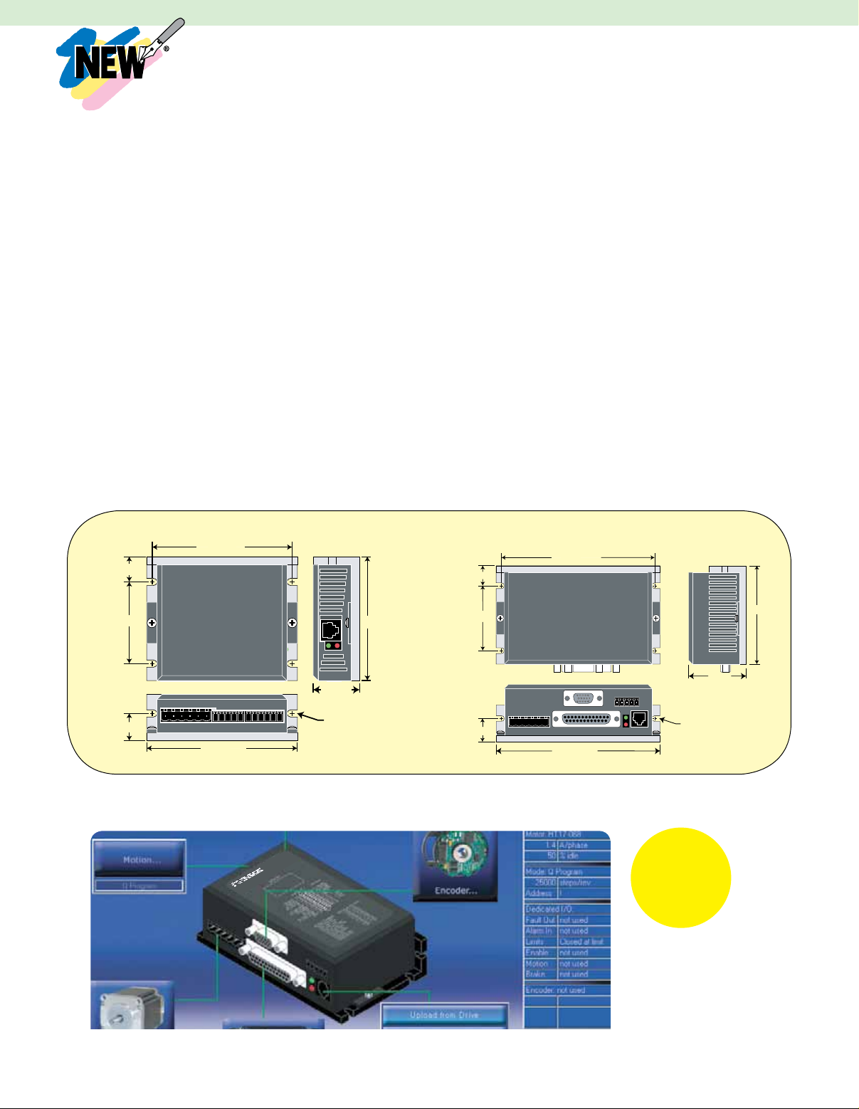
ST5-S and
ST10-S
86 (3.39)
15 (0.61)
50 (1.98)
(1.125)
17 (0.663)
93 (3.65)
Dimensions: mm (inch)
76 (3.0)
29
6X SLOT 0.16
WIDE, FULL R
15 (0.61)
50 (1.98)
)
SoftWare St configurator
ST5-Q
tm
ST5-Si and
ST10-Si
120 (4.74)
127 (5.0)
(1.75)
6X SLOT 0.16
WIDE, FULL R
Software
Included
Free with
Purchase of
ST Drives!
76 (3.0)
45
D-27
l Simple Drive Setup
l Store and Download
Configurations
Page 3

drive #1
drive #2
drive #3
drive #4
Host
PC
or
PLC
Optical
Isolation
Optical
Isolation
OUT1
OUT2
OUT3
OUT4
IN1
IN2
IN3
IN4
acceSSorieS
Multi-Axis Systems
Connect up to 4 drives on a mult-axis
system using SiNet
Hub Programmer
your sequence of events, then download
to the hub for a stand-alone system or
send serial commands to the drives from
a PC, PLC, HMI, or other host controller.
TM
Hub 444. Use SiNet
TM
software to develop
Order
HUB 444
Separately. See
omega.com
HUB 444
for Multi-Axis
Systems
RECOMMENDED POWER SUPPLIES (ORDER SEPARATELY)
ST5-S and –Si: OMPS150A24, 24 Vdc at 6.3 A. See omega.com for details.
ST10-S and –Si: OMPS300A48, 48 Vdc at 6.7 A. See omega.com for details.
FUSING
Internal Fuse: ST5 and ST10 contain internal 10 A fast acting fuses
OMRC-050 Regen Clamp—For Stepper
Drive Power Supply Protection
l Voltage Range 24 to 80 Vdc
l 50 W Power Dissipation
l Regen Present LED
l Power LED
l 76 x 102 x 6.4 mm (3 x 4 x 2.5")
SPECIFICATIONS
Input Power Cont: 50 W
Input Power Peak: 800 W
Voltage Range: 24 to 80 Vdc
Order
OMRC-050
Separately. See
omega.com
OMRC-050
shown smaller
than actual size.
Recommended When Using:
NEMA 17 motors @ speeds > 30 rps
NEMA 23 motors @ speeds > 10 rps
NEMA 34 motors @ speeds > 4 rps
HUB 444 with
DIN rail mounting
kit shown smaller
than actual size.
Order Power
Supplies
Separately. See
omega.com
OMBOB-1 Breakout Box
for I/O Connector
l Break out DB-25 I/O Connector to
Screw Terminals
l Includes 1 m (3') Cable
l Compatible with ST5-Si and ST10-Si
OMBOB-1
shown
smaller than
actual size.
Great for
prototyping
systems!
D-28
Page 4

0
01020
30
40 50
s p r
ST5
HT17-075/HT17-275
Connection: Parallel
Drive setting: 1.6 A/phase, 20,000 spr
60
50
40
30
20
10
oz-in
24 Vdc
48 Vdc
ST10
HT34-485
Connection: Parallel
Drive setting: 10.0 A/phase, 20,000 spr
24 Vdc 48 Vdc 80 Vdc
600
500
400
300
200
100
0
01020304050
oz-in
rps
s p r
ST10
HT34-486
Connecting: Parallel
Drive setting: 9.7 A/phase, 20,000 spr
24 Vdc
80 Vdc48 Vdc
1000
900
800
700
600
500
400
300
200
100
0
0
10 20 30 40 50
oz-in
ST5
HT23-400/HT23-600
Connection: Parallel
Drive Settings: 3.4A 20,000 spr
24 Vdc 48 Vdc
240
220
200
180
160
140
120
100
80
60
40
20
0
0510 15 20 25
30
35 40
Torque (oz-in)
Speed (rev/sec)
0
20
40
60
80
120
100
0510 15 20 25 30 35 40
ST5
HT23-397/HT23-597
Connection: Parallel
Drive setting: 3.4A 20,000 spr
24 Vdc
48 Vdc
160
140
Speed (rev/sec)
Torque (oz-in)
ST10
HT34-487
Connection: Parallel
Drive setting: 10.0 A/phase, 20,000 spr
24 Vdc
48 Vdc
80 Vdc
1400
1200
1000
800
600
400
200
0
010
20
30
40 50
oz-in
rps
torque-SpeeD curveS
D-29
Page 5

0
20
40
60
80
100
120
0510 15 20 25 30 35 40
ST5/ST10
HT24-100
Connection: 4 lead
Drive settings: 3.36A 20,000 spr
24 Vdc 48 Vdc
Speed (rev/sec)
Torque (oz-in)
0
20
40
60
80
100
120
140
160
180
0510 15 20 25 30 35 40
ST5/ST10
HT24-105
Connection: 4 lead
Drive settings: 4.8A 20,000 spr
24 Vdc
48 Vdc
Speed (rev/sec)
Torque (oz-in)
0
50
100
150
200
250
300
0510 15 20 25 30 35 40
ST5/ST10
HT24-108
Connection: 4 lead
Drive settings: 4.8A 20,000 spr
24 Vdc
48 Vdc
60 Vdc (ST10 drives)
350
Speed (rev/sec)
Torque (oz-in)
0
50
100
150
200
250
300
350
400
450
0510 15 20 25 30 35 40
ST10
HT34-504
Connection: Parallel
Drive settings: 7.56 A 20,000 spr
24 Vdc 48 Vdc 60 Vdc
Speed (rev/sec)
Torque (oz-in)
0
100
200
300
400
500
600
700
800
0510
15
20 25 30 35 40
ST10
HT34-505
Connection: Parallel
Drive settings: 7.56A 20,000 spr
24 Vdc
48 Vdc 60 Vdc
Speed (rev/sec)
Torque (oz-in)
0
100
200
300
400
500
600
700
800
900
1000
0510 15
20
25 30 35
40
ST10
HT34-506
Connection: Parallel
Drive settings: 6.72 A 20,000 spr
24 Vdc
48 Vdc
60 Vdc
Speed (ref/sec)
Torque (oz-in)
To Order Visit omegamation.com/st_series for Pricing and Details
MODEL NO. DESCRIPTION
ST5-S Performance stepper drive with 5 A output
ST5-Si Performance stepper drive with Si Programmer
ST5-Si-485 Performance stepper drive with Si ProgrammerTM and RS485 option
ST5-Si-ENC Performance stepper drive with Si ProgrammerTM and encoder option
ST5-Si-ENC-485 Performance stepper drive with Si ProgrammerTM and encoder plus RS485 options
ST10-S Performance stepper drive with 10 A output
ST10-Si Performance stepper drive with Si Programmer
ST10-Si-485 Performance stepper drive with Si ProgrammerTM and RS485 option
ST10-Si-ENC Performance stepper drive with Si ProgrammerTM and encoder option
ST10-Si-ENC-485 Performance stepper drive with Si ProgrammerTM and encoder plus RS485 options
Note: Software and download cable included.
Ordering Example: ST5-S, performance stepper drive with 5 A output.
TM
TM
D-30
Page 6

RECOMMENDED MOTORS FOR ST5
MODEL NO. DESCRIPTION
OMHT17-275 NEMA 17, 62.3 oz-in holding torque
OMHT24-100 NEMA 24, 123 oz-in holding torque
OMHT23-597 NEMA 23, 177 oz-in holding torque
OMHT24-105 NEMA 24, 177 oz-in holding torque
OMHT17-075 NEMA 17, 62.8 oz-in holding torque
OMHT23-600 NEMA 23, 264.8 oz-in holding torque
OMHT23-397 NEMA 23, 177 oz-in holding torque
OMHT24-108 NEMA 24, 354 oz-in holding torque
OMHT23-400 NEMA 23, 264 oz-in holding torque
Ordering Example: ST5-Si, performance stepper drive with Si ProgrammerTM, and OMHT17-075, NEMA 17 high torque step motor.
See omegamation.com for more motor specs. Torque-speed curves for recommended motor shown above.
RECOMMENDED MOTORS FOR ST10
MODEL NO. DESCRIPTION
OMHT24-100 NEMA 24, 123 oz-in holding torque
OMHT24-105 NEMA 24, 177 oz-in holding torque
OMHT24-108 NEMA 24, 354 oz-in holding torque
OMHT-34-504 NEMA 34, 396 oz-in holding torque
OMHT34-485 NEMA 34, 650 oz-in holding torque
OMHT34-505 NEMA 34, 849 oz-in holding torque
OMHT-34-506 NEMA 24, 123 oz-in holding torque
OMHT34-486 NEMA 34, 1200 oz-in holding torque
OMHT34-487 NEMA 34, 1845 oz-in holding torque
Ordering Example: ST10-Si, performance stepper drive with Si ProgrammerTM, and OMHT34-487, NEMA 34 high torque step motor.
ACCESSORIES
MODEL NO. DESCRIPTION
ENC-ST-CA-10 Encoder cable for ST drive, 3 m (10')
OMBOB-1 Breakout box for I/O connector
OMPS150A24 Stepper drive power supply for ST5 series, 24 Vdc, 6.3 A
OMPS300A48 Stepper drive power supply for ST10 series, 48 Vdc, 6.7 A
OM-CONV-USB USB to RS232 interface converter
OMRC-050 Motor regeneration clamp
POWER CORD-SE AC power cord with stripped end termination
OM-PL-USBS USB to RS232 converter; works with Windows Vista and Windows 7
OMG-USB-485-1 USB to RS422/485/530 interface converter; USB-A to DB25-male DB25F/9M cable
OMG-CA175 DB25F/9M cable (DB9 RS422 pinout)
SI-PROG-CBL Replacement programming cable (comes with drive)
DRIVE-CBL Replacement MMI and/or HUB communications cable (comes with MMI-01 and HUB 444)
DSUB-9-MF DIN rail interface module, 9-pin
DSUB-25-MF DIN rail interface module, 25-pin
DSUB-9-MF-CBL DSUB cable, 9-pin, 2 m (6.6'), male/female connectors
DSUB-25-MF-CBL DSUB cable, 25-pin, 2 m (6.6'), male/female connectors
Ordering Example: ST10-Si-ENC-485, 10 A performance stepper drive with Si programmer plus encoder and RS485 options,
ENC-ST-CA-10, 3 m (10') encoder cable for ST drive, and OMBOB-1, breakout box for I/O connector.
(DRB RS422 pinout)
D-31
 Loading...