

Page 1
MPS40
Melting Point Apparatus
®
e-mail: info@omega.com
For latest product manuals:
omegamanual.info
Shop online at
omega.com
®
User’s Guide
®
MADE IN UNITED KINGDOM
Page 2

Servicing North America:
U.S.A.: OMEGA Engineering, Inc.
ISO 9001 Certified One Omega Drive
P.O. Box 4047
Stamford, CT 06907-0047 USA
Toll-Free: 1-800-826-6342 TEL: (203) 359-1660
FAX: (203) 359-7700 e-mail: info@omega.com
Canada: 976 Bergar
Laval (Quebec), H7L 5A1 Canada
Toll-Free: 1-800-826-6342 TEL: (514) 856-6928
FAX: (514) 856-6886 e-mail: info@omega.ca
For immediate technical or application assistance:
U.S.A. and Canada: Sales Service: 1-800-826-6342/1-800-TC-OMEGA
®
Customer Service: 1-800-622-2378 /1-800-622-BEST
®
Engineering Service: 1-800-872-9436/1-800-USA-WHEN
®
Mexico/ En Español: 001 (203) 359-7803 FAX: 001 (203) 359-7807
Latin America info@omega.com.mx e-mail: espanol@omega.com
Servicing Europe:
Benelux: Managed by the United Kingdom Office
Toll-Free: 0800 099 3344 TEL: +31 20 347 21 21
FAX: +31 20 643 46 43 e-mail: sales@omegaeng.nl
Czech Republic: Frystatska 184
733 01 Karviná, Czech Republic
Toll-Free: 0800-1-66342 TEL: +420-59-6311899
FAX: +420-59-6311114 e-mail: info@omegashop.cz
France: Managed by the United Kingdom Office
Toll-Free: 0800 466 342 TEL: +33 (0) 161 37 29 00
FAX: +33 (0) 130 57 54 27 e-mail: sales@omega.fr
Germany/Austria: Daimlerstrasse 26
D-75392 Deckenpfronn, Germany
Toll-Free: 0800 6397678 TEL: +49 (0) 7056 9398-0
FAX: +49 (0) 7056 9398-29 e-mail: info@omega.de
United Kingdom: OMEGA Engineering Ltd.
ISO 9001 Certified
One Omega Drive, River Bend Technology Centre, Northbank
Irlam, Manchester M44 5BD United Kingdom
Toll-Free: 0800-488-488 TEL: +44 (0) 161 777-6611
FAX: +44 (0) 161 777-6622 e-mail: sales@omega.co.uk
OMEGAnet®Online Service Internet e-mail
omega.com info@omega.com
It is the policy of OMEGA Engineering, Inc. to comply with all worldwide safety and EMC/EMI
regulations that apply. OMEGA is constantly pursuing certification of its products to the European New
Approach Directives. OMEGA will add the CE mark to every appropriate device upon certification.
The information contained in this document is believed to be correct, but OMEGA accepts no liability for any
errors it contains, and reserves the right to alter specifications without notice.
WARNING: These products are not designed for use in, and should not be used for, human applications.
®
Page 3
Melting Point
automatic melt ing point
SMP40
Apparatus SMP40
Instructions for use
Version 1.0
Page 4

1. Introduction 1
2. Safety Advice Before Use 1
3. General Description 1
3.1 Module Separation 2
3.2 Melting Point Determination 3
3.3 Temperature Settings 3
3.4 Sample Preparation 3
4. Preparation for Use 4
4.1 Electrical Installation 4
4.2 Installation 4
5. Instrument and Software Controls 5
5.1 Instrument 5
5.2 Main Menu Screen 6
6 Setting up New Methods 10
6.1 Creating a New Method 11
6.2 Preset Methods 12
6.3 Carry out a Rapid-Melt 13
7 Performing Melt Determinations 14
8 Results 17
8.1 View Previous Results 17
8.2 Re-use Result Parameters 25
9 File Management 26
9.1 Manage Files 26
9.2 View Storage Information 28
10 Settings and Calibration 29
10.1 User Settings 29
10.2 Maintenance Settings 31
10.3 Instrument Calibration 31
11 Maintenance & Servicing 36
11.1 Repairs and Support 36
11.2 Cleaning the Sample Block 36
11.3 Accessories 36
12 Warranty 37
13 Specification 37
Page 5

1. Introduction
Thank you for purchasing this piece of Stuart
equipment. To get the best performance from the
SMP40 please read these instructions carefully
before use. Before discarding the packaging
check that all parts are present and correct.
For your own safety and that of others please
read and understand the safety advice given
below before using the equipment.
2. Safety Advice Before
Use
! If the equipment is not used in the manner
described in this manual and with accessories
other than those recommended by Stuart, the
protection provided might be impaired.
This equipment is designed to operate under the
following conditions:
❖ For indoor use only
❖ Use in a well ventilated area
❖ Ambient temperature range +5°C to +40°C
❖ Altitude to 2000m
❖ Relative humidity not exceeding 80%
❖ Mains supply fluctuation not exceeding 10%
❖ Over-voltage category II IEC 60364-4-443
❖ Pollution degree 2
Never move or carry the unit when in use or
connected to the mains electricity supply.
The unit should be carried using both hands with
fingers under each side of the frame.
The ventilation slots at the back or side of the
device should not be sealed or obstructed.
*
The number of result files that can be stored on the SMP40 is largely dependant upon the runtime and size of
the video file for each sample.
The user is able to review the result file and video, reprocessing the automatically determined results if required.
3. General Description
The device is designed to automatically measure
and record the melting temperatures of crystalline
samples held within capillary tubes. Up to three
tubes can be accommodated in an illuminated
chamber within an aluminium block. The tubes
are monitored by a digital camera; the image of
which can be viewed on the instruments display
during the melting process. The device is
designed to be independently operated using the
colour touch screen allowing all operational and
data management functions to be performed
without the need to attach an external computer
or keyboard. The unit can be split into two
modules to allow the heating module to be
located in an environment suitable for the types
of samples being tested, while the control
module can be kept in a more convenient
location.
The temperature range of the device is ambient
to 400°C and the heating rate is variable
between 0.1°C and 20°C/minute. Temperature
data and information on the instruments status is
displayed on the screen at all times. All of the
instruments functions and menus are accessed
using the colour touch screen interface which
allows fast and intuitive navigation throughout a
substance’s melting point determination (melt
determination). The instrument has sufficient
internal storage capacity for an almost unlimited
number of preset method programs and typically
between 100 and 200 result files*. When
required, result files can be transferred from the
instrument to a PC or USB flash drive for external
storage and archiving.
When a melt cycle is started the SMP40 heats up
to the pre-programmed plateau temperature at
the maximum rate before stabilising at the
plateau temperature for 60 seconds. The SMP40
will then start to heat at the pre-programmed
rate until the melt is complete or until the device
reaches a pre-determined end temperature. Once
a melt determination has been completed,
cooling is automatically engaged until the
instrument reaches 50°C.
1
Page 6
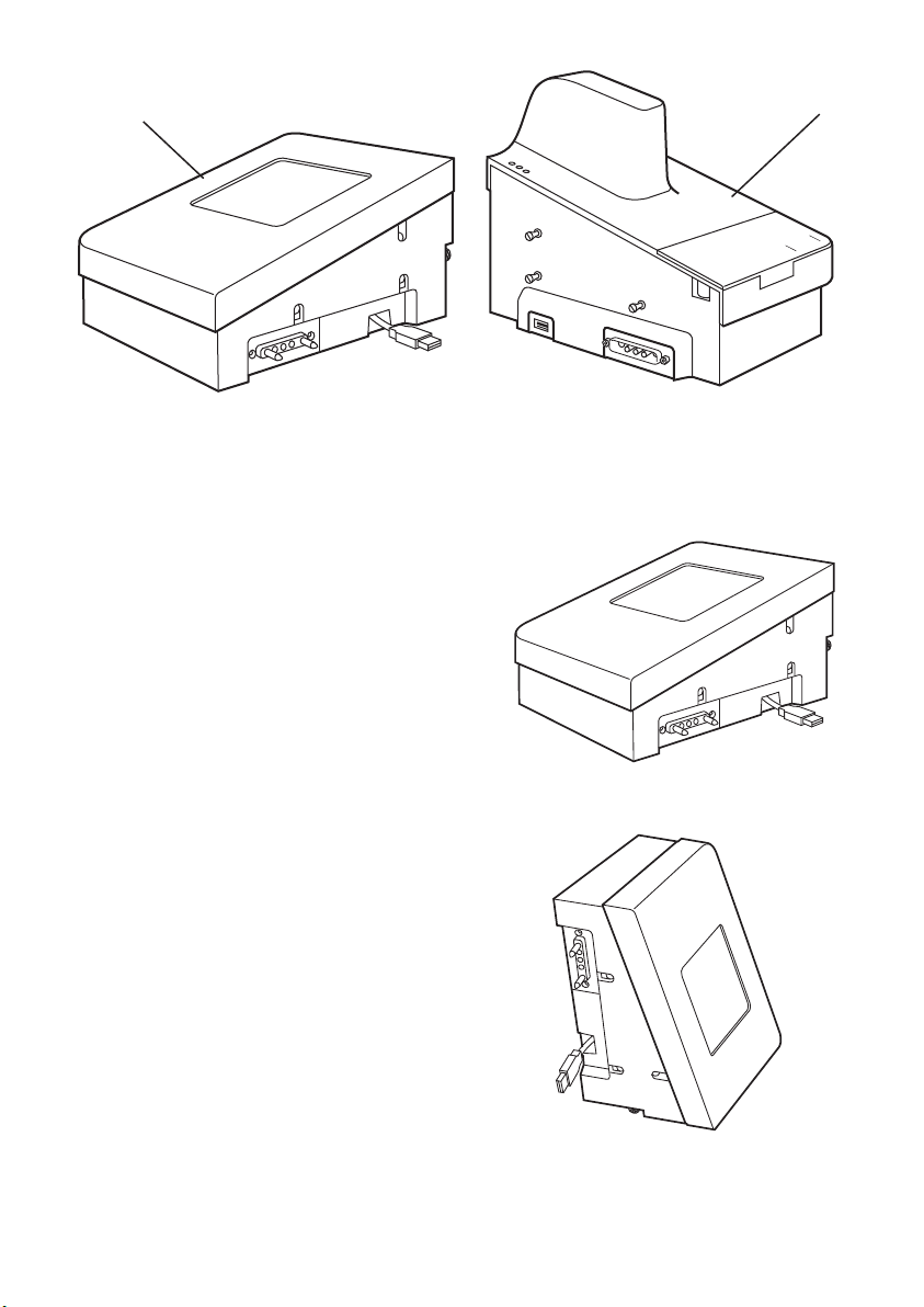
3.1 Module Separation
automatic melting point
SMP40
automatic melting point
SMP40
automatic melting point
SMP40
Control module
Figure 1: SMP40 module separation
The SMP40 can be split into two separate
modules using the split module release
mechanism located at the rear of the “Control”
module. Using the supplied accessory cables the
modules can be placed in separate locations up
to 1m apart.
Please ensure that the instruments electrical
power supply is switched off or disconnected
before commencing the following procedure.
1. Rotate the split module release mechanism
clockwise until it cannot be turned any further.
2. Gently pull the “Control” and “Melt” modules
apart taking care not to strain the connecting
USB cable.
3. Disconnect the USB cable on the control
module that connects the two modules.
4. Using the accessory cables supplied with your
SMP40 reconnect the power and USB
connections between the modules.
5. Once the devices power supply is
re-established the unit can then be used as
described in this manual.
6. Reconnecting the modules is the reverse of the
above.
Please ensure that the extension cables are
not removed from their connections when
the unit is connected to the electrical power
supply and switched on.
Melt module
The SMP40s touchscreen display is fitted with an
accelerometer device.
Flat
Upright
2
Page 7

3.2 Melting Point Determination
The capillary technique is a standard method for
determining the melting point of a substance. In
this method, thin glass capillary tubes containing
prepared samples of a substance are introduced
into the heating block of a suitable device. The
block is then heated at a fixed rate over a
temperature range that brackets the expected
melting temperature of the substance, until the
substance is completely melted (i.e. clear point).
During the heating cycle the substance under test
will often undergo a number of observable
physical changes:
1. Fine droplets adhere uniformly to the inside of
the capillary tube.
2. A clearance between the sample and the
capillary wall becomes visible.
3. The substance collapses and begins to liquefy.
4. A meniscus is visible at the samples surface
but solid particles remains visible. (Meniscus
Point)
5. The sample is a clear liquid and no solid
particles remain visible. (Clear Point)
When determining the melting point of a
substance it is necessary to select one stage in
the melting process which will be used to define
the melting point. The meniscus point or clear
point is commonly used to define the melting
point of a substance.
The SMP40 automatically reports the Clear
Point (5); the point at which the sample is a
clear liquid and no solid particles remain, as
the melting point of a substance.
Other changes in the physical appearance of the
substance are sometimes observed, such as
sublimation (transition from the solid to gas
phase with no intermediate liquid stage) or
decomposition (the separation of a substance
into its elements or smaller compounds). These
changes (if observed) should be recorded
manually.
Where a single melting point is difficult to define
for a substance it is often useful to report a
substances melting range. The melting range of a
substance is defined as the interval between the
start of a melt and the clear point.
3.3 Temperature Settings
The temperature settings used to determine a
substances melting point are critical to the
accuracy of the determination.
Start or
Plateau
Temperature:
End
Temperature:
Ramp
Rate:
Ramp rate is the most important instrument
parameter with regards to the accuracy of a
substances melt determination. The use of
fast ramp rates is the most common cause of
inaccurate melt determinations.
3.4 Sample Preparation
For accurate melting point determinations the
substance being tested should be in a dry and
uniformly powdered form. Coarse crystalline and
non-homogeneous samples should be crushed
into a fine powder using a pestle and mortar
before the substance is introduced into a capillary
tube.
Each capillary tube in a substances melt
determination should be prepared in the same
way. The open end of a capillary tube is pressed
gently into a small amount of powdered
substance until the capillary contains sufficient
material to form a compact layer of 2.5-4.5mm in
height. The powder is then forced to the bottom
of the tube by repeatedly tapping the bottom of
the capillary against a hard surface.
Excessive amounts of sample in the capillary
tubes will result in inaccurate melt
determinations.
The start temperature is usually
set 5 or 10˚C below the
expected melting point of the
substance.
The end temperature is set at a
temperature where all physical
changes in the substance are
expected to be complete.
The ramp rate is the rate at
which the sample block is
heated during the melt
determination. For accurate
determinations a rate of
between 0.5˚C/min and 2.0˚C/
min is recommended.
3
Page 8

The SMP40 can accommodate up to three sample
capillaries. For accurate melting point
determinations it is recommended that three
samples of the same material are prepared in the
same way and analysed at the same time. The
average of the three capillaries results can then
be reported as the substances melting point.
The appropriate mains lead should be connected
to the instrument BEFORE connection to the
mains supply. Should the mains lead require
replacement, a cable of 1mm
code H05VV-F connected to an IEC320 plug
should be used. The UK mains lead is protected
by a 10A fuse mounted in the plug top.
2
of harmonised
4. Preparation for Use
4.1 Electrical Installation
THIS EQUIPMENT MUST BE EARTHED
Before connecting the instrument, please read
and understand these instructions and ensure
that the electrical supply corresponds to that
shown on the rating plate. This unit is designed
for use with a supply rated at 115/230V,
50-60Hz. The power consumption of the unit is
60W. The unit is fitted with an IEC socket at the
side of the instrument for connection of the
mains lead.
Caution: Fuses are fitted in both live and
neutral lines.
The unit is supplied with two mains leads fitted
with IEC plugs. One lead has a UK 3 pin plug and
the other has a 2 pin “Shuko” plug for
connection to the mains supply. Choose the lead
appropriate for your electrical installation and
discard the other. Should neither lead be suitable
take the lead with the UK plug and replace the
plug with a suitable alternative. This involves
cutting off the moulded plug, preparing the cable
and connecting to the rewireable plug in
accordance with its instructions.
IT IS IMPORTANT THAT THIS OPERATION
SHOULD ONLY BE UNDERTAKEN BY A
QUALIFIED ELECTRICIAN.
Refer to the equipment’s rating plate to ensure
that the plug and fusing are suitable for the
voltage and wattage stated. The wires in the
mains cable are coloured as follows:
LIVE BROWN
NEUTRAL BLUE
EARTH GREEN/YELLOW
4.2 Installation
Connect the unit to the electricity supply but DO
NOT SWITCH ON. Place the unit on a firm, level,
non-slip surface ensuring that there is sufficient
free space on all sides without coming into
contact with anything else during use. Switch the
unit ON at the mains On/Off switch on the side
of the instrument. When switched ON, the touch
screen display will illuminate and the interface
software will load within 30 seconds.
IF IN DOUBT CONSULT A QUALIFIED
ELECTRICIAN
The sample block will become hot during
operation.
4
Page 9
5. Instrument and Software
automatic melt ing point
SMP40
Controls
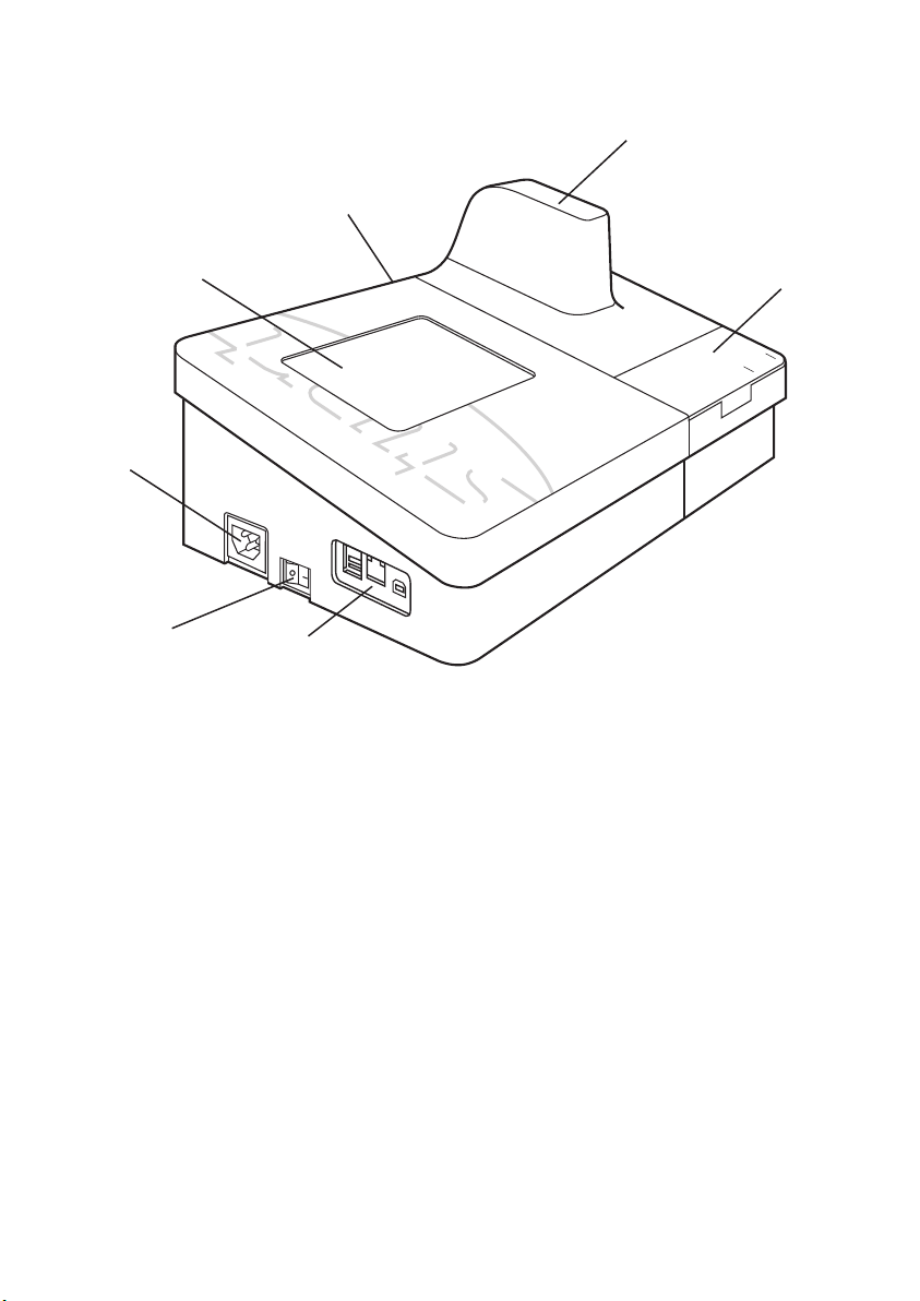
5.1 Instrument
Touch Screen
Interface and
Display
A/C power
input
Split Module Release
Mechanism
Sample Compartment
Capillary Storage
and Cutter
ON/OFF Switch
Mains On/Off: This is a rocker type switch found on the left hand side of the
unit. Pressing the “I” switches the unit ON. Pressing the “O”
switches the unit OFF.
Sample Compartment: This lifts to provide access to the sample block which is capable of
holding three capillary sample tubes.
Capillary tubes must be a minimum of 5.0cm in length to
ensure that they can be retrieved from the sample block.
Capillary Storage and Cutter: A compartment is provided for the storage of the glass capillaries
used in the melt determinations and incorporates a device to cut
capillary tubes.
Touch Screen Interface The touch screen interface is used to perform all control
and Display: functions on the SMP40. Live images of the sample compartment,
real-time data on the instrument’s status and the sample block’s
temperature can also be viewed on this display.
USB and Ethernet A USB flash drive can be inserted into the one of the USB ports,
Connections: allowing result files to be copied or moved from the device. If the
unit is to be connected directly to a PC please contact the technical
support department for advice. See page 35 for contact details.
The ethernet port is for service and support use only.
USB and Ethernet
Connections
Figure 2: SMP40 front view
5
Page 10

5.2 Main Menu Screen
Figure 3:
Main Menu
When the instrument is first switched on the display will show “LOADING PLEASE WAIT” message.
After 30 seconds the display will show the main menu screen and the four main menu options:
Measurement: This menu gives access to options that allow a new melt determination to be
performed using new, previously stored or preset method parameters.
Results: This menu gives access to the result files stored on the device. The result files report and
video file can be accessed from this menu.
File Management: This menu allows result files on the device to be copied or moved to an inserted
USB flash drive. The devices storage information is also displayed in this menu.
Settings and Calibration: This menu gives access to the devices user adjustable settings and also
allows the device to be recalibrated if required.
The Stuart SMP40 is controlled solely through the touch screen interface of the instrument. The
header bar is located at the top of the screen in most menus within the software interface.
Back button
Figure 4: The
Touchscreen
Header Bar
Back Button: Used to return to the previous screen at anytime
Block Temperature: Displays the actual temperature reading from the sample block
Time and Date: Displays the current time and date in the format specified in the user settings
Menu Title/Name: Displays the current menus title or name
Instrument Status: Displays the current instrument status
Home Button: Used to return to the main menu at anytime
Menu title/name Instrument status
Home button
6
Page 11

The command toolbar is located at the bottom of the screen in most menus within the software
interface. The command toolbar will give the user either one or two options based upon the menu
shown.
Figure 5: The Command Toolbar
If the number of options available in a menu exceeds the number that can be displayed on the screen,
a scrollbar will be displayed on the right hand side. Pressing the arrows at the top and bottom of the
scrollbar enables the list of options available in the menu to be seen.
The following controls are used to input data and adjust settings on the instrument:
Alphanumeric: Alphanumeric data can be
entered.
Numerical: Numerical data can be entered.
Date: Calender date information can be entered.
Time: 12/24hr time information can be entered.
Listed Options: Setting specific options can be
selected.
Drop Down List: Field specific options can be
selected.
Toggle Selection Field: Option is not selected or
selected respectively.
Other keys used:
BCK Removes the character directly behind the cursor or the highlighted characters.
DEL Removes the character directly in front of the cursor or the highlighted characters.
SHIFT Toggles the keypad between higher and lower case letters for one character entry.
CAPS Toggles the keypad between higher and lower case letters for all characters entered.
CLR Clears the characters in the current entry.
To change the data in each of these fields the screen should be pressed within the border of the control.
The interface used to add or change the setting depends on the type of control.
7
Page 12

5.2.1 Alphanumeric Entry Field
1 Selecting an Alphanumeric Entry Field opens
the text keypad interface.
2 The alphanumeric entry field can be
populated with letters (Abc), numbers (123)
or symbols (SYM). Text, numbers and symbols
are accessed using the Abc, 123 and SYM
keys on each of the respective keypads.
3 Entries are confirmed by pressing the “Accept
this text” button on the command toolbar.
5.2.2 Numerical Entry Field
8
1 Selecting a Numerical Entry Field opens the
numeric keypad interface.
2 The numeric entry field can only be populated
with numbers.
3 Entries are confirmed by pressing the “Accept
this number” button on the command
toolbar.
Page 13

5.2.3 Date Entry Field
5.2.4 Time Entry Field
1 Selecting a Date Entry Field opens the date
keypad interface.
2 The date entry field is displayed in the
format specified in the User Settings menu.
3 Press the arrows above and below each
number to increase or decrease the value
displayed.
4 Entries are confirmed by pressing the
“Accept this date” button on the
command toolbar.
1 Selecting a Time Entry Field opens the time
keypad interface.
2 The Time Entry Field is displayed in the 24
hour format.
3 Press the arrows above and below each
number to increase or decrease the value
displayed.
4 Entries are confirmed by pressing the “Accept
this time” button on the command toolbar.
5.2.5 Listed Options Field
1 Selecting a Listed Options Field opens the
listed options keypad interface.
2 The options available in the Listed Options
entry field is specific to each individual
setting. e.g. The Temperature Units setting
gives the options Celsius (˚C), Fahrenheit (˚F)
and Kelvin (K).
3 Use the scrollbar to view the full list of
available options for each setting.
4 The option that is required is selected by
pressing on the required option button.
9
Page 14

5.2.6 Drop Down List Field
5.2.7 Toggle Selection Field
6. Setting up New Methods
1 Selecting a Drop Down List Field displays the
options available for that field.
2 Arrows keys may be displayed to indicate that
further options are available. Use the arrow
buttons to view the additional options.
3 Press the required option from the list to
select it.
1 Pressing a Toggle Selection Field will add or
remove the check mark in that field.
2 A check mark indicates that the option is
active.
Touching the measurement section on the main menu screen will open the measurement menu where
three options are available:
Create a new measurement: This option
allows a new melt determination to be started.
Measurement parameters such as the Sample
Name, Start Temperature and Ramp Rate need to
be entered when using this option.
Use a preset from the library: This option
allows a new melt determination to be started
using measurement parameters stored previously
on the device.
Carry out a rapid-melt: The device will roughly
determine the melting point of the sample using
preset measurement parameters.
10
Page 15

6.1 Creating a New Method
In the Measurement menu screen touch the “Create a new measurement” section of the screen.
1 Enter a sample name for the samples by
selecting the Sample Name field
2 Enter an appropriate start or plateau
temperature for the sample by selecting the
Start Temperature field.
3 Enter the required temperature ramp rate for
the samples by selecting the Ramp Rate field.
4 Optional sample and method information is
accessed by pressing the “Touch here to enter
additional information” button. If this is not
required press “Continue” and go to step 8.
5 The SMP40 will automatically detect the end
of the melt when the toggle selection field
has an X in the Automatically detect the melt
end field. Removing this check mark allows a
value to be entered into the End Temperature
field.
6 Enter any batch or reference details in the
Batch/Reference alphanumeric entry field.
7 To proceed to the melt determination select
“Go back to main information” and then
select “Continue”.
8 The option of saving this new method as a
preset method will be given. Select “Yes” to
save the method for future use or select
“No” to proceed without saving the method.
11
Page 16

6.2 Preset Methods
In the Measurement menu screen touch the “Use a preset from the library” section of the screen.
1 In the preset methods screen select the
method to be used for the melt
determination by pressing on the method
details.
2 Press “Select preset and continue”.
3 Method parameters such as the Sample
Name, the Start Temperature and the Ramp
Rate can then be adjusted if required by
selecting the relevant field.
4 Optional sample and method information is
accessed by pressing the “Touch here to enter
additional information” button.
12
5 Method parameters can be adjusted if
required. The SMP40 will automatically detect
the end of the melt when the toggle selection
field has an X in the “Automatically detect
the melt end” field. Removing this check
mark allows a value to be entered into the
End Temperature field.
6 Enter any batch or reference details in the
Batch/Reference alphanumeric entry field.
7 To proceed to the melt determination, select
“Go back to main information” and then
select “Continue”.
Page 17

8 The option of saving this new method as a
new preset method will be given if the
sample name has been changed. Select “Yes”
to save the method for future use or select
“No” to proceed without saving the method.
9 If changes are made to the temperature
settings the user will be asked whether they
wish to overwrite the existing preset method
of that name. Select “Yes” to save the new
method settings for future use or select “No”
to proceed without saving the new settings.
6.3 Carry out a Rapid-Melt
If the user is unsure of the start temperature that should be specified in a melt determination method
they can use the rapid melt function to quickly determine an approximate melting temperature.
In the Measurement menu screen touch the “Carry out a rapid-melt” section of the screen.
1 The rapid melt function will heat the sample
from 50.0˚C at 20.0˚C/min until the sample
has melted.
2 The results will be reported on the screen as
shown in the example opposite.
3 The results from the rapid melt analysis can
then be used to facilitate the setting of the
start temperature on a more accurate melt
determination.
13
Page 18

7. Performing Melt Determinations
Once the analysis method and sample information have been entered into the SMP40 software the
instrument will display the New Measurement screen.
Current block
temperature
Sample name
Method
information
Live image
of the
sample
compartment
Figure 6: New Measurement Screen
The Capillary tubes melt status is for Information Only. An accurate analysis of the data is
performed after the melt determination has been completed.
Capillary
tubes melt
status
14
1 Place 1-3 prepared melting point capillaries
into the SMP40 sample compartments sample
block.
The external surface of the sample
capillaries must be wiped clean before being
placed into the sample block as chemical
residues may build up and affect the
performance of the device.
2 Press “Start the melt” to initiate the melting
protocol.
Page 19

3 The instrument status will change to
“Heating” and the command toolbar options
will change.
4 The SMP40 will quickly heat the sample block
to the set start temperature.
5 When the sample block reaches the start
temperature the SMP40 status will change to
“Stabilising” and the temperature of the
sample block will remain constant for 60
seconds.
6 After the instrument has stabilised at the start
temperature the status will change
automatically to “Analysing” and the
instrument will begin to heat the sample
capillaries at the specified ramp rate.
7 The Capillary tubes melt status is shown to
indicate the melt determinations progress.
The Capillary tubes melt status is shown for
Information Only.
15
Page 20

8 As the melt determination progresses the
capillary tube melt status changes through:
Solid: No changes have been detected in the
samples physical form.
Melting: The sample is showing the first signs of
a change in its physical form.
Liquid: The change in the samples physical form
is complete.
Finished: Once a capillary tube displays
“finished” the melt determination is complete.
Once all of the sample capillaries are deemed to
have finished, or the instrument reaches the
previously specified end temperature, the
instrument will complete the measurement and
display the samples analysis report.
At any time in the melt determination pressing
the “Stop and go back” button will end the melt
determination and save any data collected up
until that point.
16
Once the melt determination is complete the
analysis report will be displayed. The analysis
report displays the following information:
Statistical Analysis: The mean and standard
deviation are calculated for the clear point values
in the melt determination.
Method Information: Sample name, Filename,
Batch reference, Start and end temperatures,
Ramp rate, Time created, Date created, and
Calibration factor.
Individual Capillaries Results: Intensity graph,
melting range and clear point.
Page 21

8. Results
Touching the results section on the main menu screen will open the results menu. Two options are
now available:
View previous results: Displays the result files
of melt determinations previously carried out on
the device which are currently located on internal
storage.
Re-use result parameters: A result can be
selected and a repeat melt determination carried
out using the method settings from that result.
8.1 View Previous Results
In the Results menu screen touch the “View previous results” section of the screen. The View Results
screen allows the user to perform a number of actions with the result files stored on the instrument.
The actions available are displayed in the Results Toolbar.
Results
toolbar
Individual
sample results
Figure 7: View
Results Screen
The View Results screen allows the user to perform a number of actions with the result files stored
on the instrument. The actions available are displayed in the Results Toolbar.
Sort/Search: The Sort/Search function is used to display the stored result files in accordance with
the rules specified in this option.
Open: The Open action is used to display the Report screen for the selected result.
View Video: The View Video action is used to display the Video Replay screen for the selected
result.
17
Page 22

Rename: The Rename action is used to change the Sample Name for the selected result.
Delete: The Delete action is used to delete the selected result from the instruments internal storage.
8.1.1 Sort/Search Function
In the menus that display the stored methods and
results the user has the option to organise the
displayed data using either a sort by or search for
function.
Sort:
1 Pressing the “Sort/Search” button will change
the tool bar to allow the user to specify which
function is required.
2 Pressing the “Sort By” button will display the
sort toolbar options.
3 The sort toolbar allows a method or
parameter to be selected to organise the
displayed data.
4 Select the parameter to be used to organise
the displayed data by pressing the
appropriate button.
5 Pressing the button twice will reverse the
order or the displayed data.
6 Highlight the required result file and press the
“Select result (or preset) and continue”
button.
7 The “Other” button on the toolbar can be
used to access additional parameters such as
Filename, Start Temperature, End Temperature
and Ramp Rate with which to sort the
displayed files.
18
Search
1 Pressing the “Sort/Search” button will change
the tool bar to allow the user to specify
which function is required.
2 Pressing the “Search By” button will display
the search options screen.
3 Pressing on a data entry field allows the user
to define the search criteria for that field.
Page 23

4 The required option should be selected from
the displayed list or alternatively enter the
search criteria using the keypad that is
displayed.
5 When the search criteria have been finalised,
press “Apply this search”.
6 Only the results that match the search criteria
specified will now be displayed.
7 Pressing the “Sort/Search” and “Search”
buttons again will display the search results
summary and allow a new search to be
started.
8 Press the “Search again” button to apply new
search criteria.
9 Press the “Clear search” button to remove
the specified search criteria.
19
Page 24

8.1.2 Opening Results Files
When a melt determination is complete or a
result file is opened, the screen will display the
Report Screen.
The report displays the following information:
The mean clear point: The average of the
sample capillaries clear point values is
automatically calculated.
The standard deviation of the clear points:
The standard deviation of the sample capillaries
clear point values is automatically calculated.
Method information: The Sample name,
Filename, Batch reference (if entered), Analysed
temperature range, Ramp rate, Time created,
Date created, and Calibration factor are all
displayed in the analysis report.
Intensity graphs for each capillary tube: The
device continuously measures each capillary tubes
image intensity value during the melt
determination. These graphs show how the
intensity value changes throughout the melt
determination. Coloured lines indicate the start
(green) and end (red) of the melting range.
Recorded events for each capillary tube:
Automatic and any manually recorded events are
displayed for each capillary tube.
Use the scrollbar to review the data
contained in the report: Use the arrows to
scroll up and down the report.
If a video record of the melt determination has
been stored it can be reviewed by pressing the
“View the video” button on the command
toolbar.
20
Page 25

8.1.3 Viewing Videos
When a video record is accessed the Video Replay screen is displayed.
Block
temperature
at specific
time
Selected
capillary
Video replay
window
Displays report
information
summary
Tagged event
selection
Video
controls
Figure 8: Video Replay Screen
The Video Replay screen is designed to allow the user to review the recorded video of a melt
determination and reprocess the results if required.
Block temperature at specific time: The temperature of the sample block at the specific timeframe
displayed in the video replay window.
Report information: Pressing the “Touch for automatically calculated values” button displays the
screen below. Each capillary tube has its start temperature, end temperature and clear point displayed.
In addition, the mean value of the start and end temperatures is calculated and displayed.
Press the “Hide” button to return to the Video Replay screen.
Tagged event selection: During the melt determination additional events may occur that are
required to be recorded in the report. Pressing this button accesses the list of available events that can
be added to the analysis report.
Capillary selection: In order to record a manual event you must first select the number of the
capillary tube it applies to by using these buttons.
Video replay window: The Video replay window displays the images that were recorded during the
substances melt determination. To view the image in full screen mode press the video replay window.
Pressing the screen again will return the device to the normal Video Replay screen.
Video controls: The Video controls are used to control the playback of the substances melt
determination video.
Capillary
selection
buttons
21
Page 26

1 To start the video replay press the play button
(
) in the video replay controls. Once the
play button has been pressed it will change to
a pause symbol (
2 The video replay scrollbar will move and
display the elapsed time in the format
mins:seconds.
3 The scrollbar can be used to quickly move to
any timeframe within the video file. Touch the
scrollbar and whilst still touching the screen,
drag the scrollbar to the required timeframe.
4 Pressing the X2 button will double the speed
at which the video is replayed.
).
❙❙
5 The restart button (
return the beginning of the video file.
Manual Events
Each melt determination may contain events of interest that require highlighting in the report. The
SMP40 allows the user to review the melt video and add defined event information to specific
timeframes for each individual capillary tube. Both the automatically determined events and any
manually added events are shown in the analysis report.
The Tagged Events field can be used to add the following events:
Clear point: The sample is a clear liquid. Solid particles are no longer visible.
Collapse point: The substance collapses and begins to liquefy.
Decomposition point: The separation of a substance into its elements or smaller compounds. Often
seen as discolouration or charring of the sample.
End of melt: The point at which no further changes in the physical form of the substance are being
seen.
Start of melt: Droplets of liquid are clearly visible for the first time.
Meniscus point: A meniscus becomes clearly visible at the surface of the sample but solid particles
remain visible in the liquid.
Sublimation point: The substance undergoes a transition from the solid to gas phase with no
intermediate liquid stage.
Other: Use this tag if an event occurs that is not accurately described by the events listed previously.
❙) can be pressed to
22
Page 27

1 Select the capillary tube to which the manual
event is to be added by pressing the relevant
“Capillary selection” button.
2 Select the timeframe in the video file, where
the manual event is to be added, using the
video replay scrollbar and the video controls.
3 A manually determined event is added to the
timeframe by pressing the “Tagged Events”
field and selecting the required event from
the drop down list.
Manual events can only be used once in each
capillaries report. e.g. A capillary cannot
have more than one Meniscus Point.
4 Additional manual events can be added by
repeating the process described in steps 2
and 3.
5 If a manual event needs to be deleted,
pressing the X next to the manual event will
delete that event.
6 After the manual events have been added for
each capillary tube select “Save manual
overridden tags”. The screen will then go
back to the previously displayed screen.
23
Page 28

8.1.4 Renaming Result Files
The melt determination report is updated with
any manual events that are added and saved. An
asterisk next to the event name is used to denote
that it has been manually added by the user.
CAUTION: IF A MANUAL CLEAR POINT EVENT
IS ADDED BY THE USER, THE TEMPERATURE
VALUE IN THE MANUAL EVENT WILL BE USED
TO CALCULATE THE SAMPLES REPORTED
MELTING POINT.
1 When the “Rename” button is pressed for a
result a rename dialogue box is opened.
2 Press the alphanumeric entry field (Abc) in the
dialogue box to enter a new Sample Name for
the selected result.
24
3 The new Sample Name is then displayed in
the alphanumeric entry field. Select “OK” to
confirm the change to the results Sample
Name. Select “Cancel” to retain the current
Sample Name.
Page 29

8.1.5 Deleting Result Files
8.2 Re-use Result Parameters
1 To delete individual results from the
instruments memory highlight the result to be
deleted and press the “Delete” button on the
Result Toolbar.
2 A confirm delete dialogue box will appear
asking the user to confirm the action. Select
“Yes” to confirm or “No” to cancel.
In the Results menu screen touch the “Re-use
result parameters” section of the screen.
1 In the Repeat Measurement screen highlight
the result file to be repeated.
2 Press “Select result and continue”.
3 The method parameters used previously will
be loaded into the Create New Method
screen.
4 Method parameters and information can be 4
adjusted and a new measurement initiated as
described on page 14.
25
Page 30

9 File Management
Touching the File Management section on the main menu screen will open the File Management
menu. Two options are now available:
Manage files: Result files can be copied, moved
or deleted from the devices internal storage.
View storage information: Displays status
information on the internal storage or an inserted
USB flash drive.
9.1 Manage Files
In the File Management menu screen touch the Manage files section of the screen.
Manage files
toolbar
Individual
sample
results
Figure 9:
Manage Files
Screen
The View Results screen allows the user to perform a number of actions with the result files stored on
the instrument. The actions available are displayed in the Result Toolbar:
Sort/Search: See page 18
Select All/Clear Selection: The Select All/Clear Selection action is used to select all of the result files
on the instrument or it can be used to deselect the result files currently highlighted.
Copy: The Copy action is used to copy the selected result files to the inserted USB flash drive.
Move: The Move action is used to move the selected result files to the inserted USB flash drive.
Delete: The Delete action is used to delete the selected result files from the instruments memory.
26
Page 31

9.1.1 Select All/Clear Selection
9.1.2 Copying Files
1 Pressing the “Select All” button in the Manage
Files toolbar will highlight all of the result
files.
2 If any of the result files in the Manage Files
screen are selected, the “Select All” button
will change to a “Clear Selection” button.
Pressing the “Clear Selection” button will
deselect all the highlighted result files.
1 Result files can be copied to an inserted USB
flash drive by highlighting the files to be
copied and pressing the “Copy” button in
the Manage Files toolbar.
2 A window is displayed to show the progress
of the copy action.
Copying a typical 5MB result and video file will
take approximately 10 seconds.
9.1.3 Moving Files
1 Result files can be moved to an inserted USB
flash drive by highlighting the files to be
moved and pressing the “Move” button in
the Manage Files toolbar.
2 A window is displayed to show the progress
of the move action.
Moving a typical 5MB result and video file will
take approximately 10 seconds.
27
Page 32

9.1.4 Deleting Files
3 Once the move action has been completed
the files will no longer be available on the
instrument so ensure that no further
reprocessing of the results is required before
using the move action as it is not possible to
move the file back, from the USB flash drive
to the instrument, once the action is
complete.
1 To delete results from the instruments
memory highlight the results to be deleted
and press the “Delete” button on the
Manage Files Toolbar.
2 A confirm delete dialogue box will appear
asking the user to confirm the action. Select
“Yes” to confirm or “No” to cancel.
9.2 View Storage Information
In the File Management menu screen touch the View storage information section of the screen.
1 The Storage Details screen displays
information on the status of the internal
memory.
Information displayed includes:
Total storage capacity.
Available storage capacity.
Details on the types of files stored on the
instrument.
2 If a USB flash drive is inserted, a summary of
the flash drives storage information can be
displayed by pressing the Change to inserted
USB flash drive section of the screen.
28
Page 33

10 Settings and Calibration
Touching the Settings and Calibration section on the main menu screen will open the Settings and
Calibration menu. There are three options available:
Change user settings: Settings that relate to
how the device operates and displays information
can be viewed and adjusted in this menu.
Change maintenance settings: The devices
software can be upgraded and the touch screen
can be recalibrated in this menu.
Manage device calibration: This menu can be
used to recalibrate the device and view stored
information on the devices calibration history.
10.1 User Settings
The following user settings can be accessed and adjusted by pressing the Change user settings section
of the Settings and Calibration screen.
Date format: The devices displayed date can be set to UK or US format.
Time format: The devices displayed time can be set to 12 or 24 hour format.
Temperature unit: The devices displayed temperature unit can be set to centigrade (˚C), fahrenheit
(˚F) or Kelvin (K).
Camera gain: The devices camera gain can be adjusted to make the image of the sample capillaries
darker or brighter. Three settings of Low, Normal and High are available. The “Low” settings will
reduce the brightness of the image compared to the “Normal” setting and the “High” setting will
increase the brightness of the image compared to the “Normal” setting. The “Normal” setting should
be suitable for most melt determinations.
Calibration frequency: The frequency at which the device is recommended to be recalibrated can be
specified using this option. The available options are Never, Weekly, Monthly, Bi-annually and Yearly.
When a melt determination is initiated, the dialogue box below will be displayed if the time period
specified in this setting has elapsed since the previous calibration. Pressing “OK” will allow the user to
continue with the melt determination.
The dialogue box will be displayed each time a melt determination is initiated, until the device is
recalibrated or the calibration frequency setting is changed.
29
Page 34

Set time: The devices displayed time can be set using the time keypad interface.
Set date: The devices displayed date can be set using the date keypad interface.
Save melt video: If the video files of the devices melt determinations do not need to be stored,
remove the check mark in this Toggle Selection field.
Use sounds for events: If sounds are not required for events that occur on the device, remove the
check mark in this Toggle Selection field.
Use sounds for screen touches: If a sound is not required to confirm each time the touch screen is
pressed, remove the check mark in this Toggle Selection field.
In the Settings and Calibration menu screen
touch the Change user settings section of the
screen.
1 The Change User Settings screen displays the
current status of all the user adjustable
instrument settings.
2 To adjust any of the displayed settings, touch
the individual settings control field and a new
setting can be entered by following the
control instructions on pages 11 and 12.
3 When the required adjustments have been
made press “Save these settings” on the
command toolbar to apply them.
30
Page 35

10.2 Maintenance Settings
In the Settings and Calibration menu screen touch the Change maintenance settings section of the
screen. The Maintenance screen allows the user to upgrade the version of software on the instrument
and to recalibrate the touch screen.
1 To upgrade the instruments software, firstly
download the new software version onto a
USB flash drive. Insert the USB flash drive into
one of the SMP40’s USB ports and touch the
“Press to upgrade” button. The new software
version will be automatically installed onto
the instrument.
Do not switch off the device or attempt to
remove the USB flash drive during this
process.
2 To recalibrate the touch screen touch the
“Press to enter screen calibration” button and
follow the on-screen instructions.
10.3 Instrument Calibration
To ensure that the instrument is operating correctly, periodic checks on the accuracy of the instruments
temperature readings are commonly performed. If the accuracy of the instrument is found to deviate
from the specification or if it is a requirement of your local quality policy, the following procedure can
be used to recalibrate the displayed temperature on the instrument.
It is recommended that the recalibration procedure is performed using suitable certified reference
materials (CRM’s), as this will ensure the highest levels of confidence is maintained in the results
generated with the instrument. The World Health Organisation (WHO) gives a list of suitable CRM’s
which includes the following materials:
Material Nominal Melting Point
Azobenzene 69 °C
Vanillin 83 °C
Benzil 96 °C
Acetanilide 116 °C
Phenacetin 136 °C
Benzanilide 165 °C
Sulfanilamide 166 °C
Sulfapyridine 193 °C
Dicyanodiamide 210 °C
Saccharin 229 °C
Caffeine 237 °C
Phenolphthalein 263 °C
31
Page 36

For information on where to purchase suitable certified reference materials please contact us:
stuarthelp@bibby-scientific.com
Tel: +44 (0)1785 810433
In the Settings and Calibration menu screen touch the Manage device calibration section of the screen.
Current
calibration
factor
Current calibration
type
Time and type
of current
calibration
Date of next
calibration
Figure 10: Calibration Screen
The Calibration screen shows the following information:
Current calibration factor: The current calibration factor of the device
Calibration type of the current calibration: Three types of calibration are possible: Single, Dual
and Factory.
Time and date of current calibration: Displays the time and date of the current calibration.
Date when next calibration is due: Displays the date when the next calibration is due to be
performed as specified in the user settings.
Previous calibration history: Displays a summary of the devices historical calibrations including the
time, date, type and calibration factor.
Calibration
history
window
32
Page 37

10.3.1 Current Calibration Factor
Results Calibration Factor
�
�
The current calibration factor shows the factor which is used to calculate the displayed block
temperature on the device.
Displayed Block Temperature = Instruments Sensor Temperature x Calibration Factor
To calculate a new calibration factor the instrument uses the following equation.
New Calibration Factor Calculation:
Calibribration = Expected Melting Point
Factor
Please see the following calibration procedure for more details on calibrating the instrument.
10.3.2 Calibration Procedure
The SMP40 allows the user to perform either a single or dual point calibration by using the following
procedure.
1 Using a suitable certified reference material,
perform a melt determination as described in
section 7.
2 If a dual point calibration is required, perform
a second melt determination on a certified
reference material with a different melting
point to that used in step 1.
3 If manual events need to be added to a result
file, they should be added using the steps
described on page 22 before starting the
recalibration procedure below.
4 In the Settings and Calibration screen select
the Manage device calibration section of the
screen.
5 In the Calibration screen press the “Calibrate
this device” button on the Command toolbar.
6 The Set Calibrated Values screen is used to
select the result files that will be used to
calibrate the instrument.
7 Select the first result to be used by pressing the
“Choose Result” field next to Value 1.
33
Page 38

8 In the Select Calibration screen highlight the
result file to be used for the first calibration
point.
9 Press the "Select result and continue" button
on the Command toolbar.
10 The results melting point (mean clear point) is
now displayed in the field. If the selected
result needs to be changed press this field
again and go to step 8.
11 If a dual point calibration is required press the
“Choose Result” field next to Value 2 and
repeat the selection process described in
steps 8 to 10.
34
12 Enter the certified melting point (clear point)
of the reference material/s in the respective
“Expected” numerical entry field/s.
13 The new calibration factor is calculated and
displayed on the screen.
14 To accept the new calibration factor press the
“Apply this calibration” button on the
Command toolbar.
Page 39

15 The calibration screen is now updated to
show the new calibration details. The
Calibration history window will now update
to display details of the previous calibration.
16 If a calibration record needs to be deleted,
pressing the X next to the calibration record
will display a confirm deletion dialogue box.
Press “YES” to confirm or “NO” to cancel.
35
Page 40

11. Maintenance
& Servicing
WARNING: Ensure the unit is disconnected
from the mains electricity supply before
attempting maintenance or servicing.
This equipment does not require routine
servicing. The only maintenance required is to
clean internal and external surfaces using a damp
cloth and mild detergent solution. Do not use
harsh or abrasive cleaning agents.
11.1 Repairs and Support
Any repairs or replacement of parts MUST be
undertaken by suitably qualified personnel. Only
spare parts supplied or specified by Stuart or its
agents should be used. Fitting of non-approved
parts may affect the performance and safety
features designed into the instrument. For a
comprehensive list of parts required by service
engineers conducting internal repairs please
contact the service department quoting the
model and serial number:
Email: service@bibby-scientific.com
Tel. +44 (0)1785 810475
Fax: +44 (0)1785 810471
For any other technical enquiries please contact
the Technical Support Department at;
Email: stuarthelp@bibby-scientific.com
Tel: +44 (0)1785 810433
2 Remove the plastic cover from the
instruments melt module.
3 Remove the ceramic sample block cover
and the metal plate covering the
sample block chamber by lifting them
clear of the instrument.
4 Unscrew the two thumbscrews on
either side of the sample block and lift
it out of the instrument. Take care not
to damage the wiring that is connected
to the sample block during its removal.
5 Using a pair of long nosed pliers or
small tweezers remove the circlip from
the sample blocks glass window.
6 The glass window is removed by gently
agitating the sample block until the
window is dislodged form the sample
block.
7 Debris can now be removed from the
sample block. Please ensure the
window is clean before reassembly as
any grease or dirt on the glass could be
detrimental to the instruments
performance.
11.2 Cleaning the Sample Block
Occasionally it may be necessary to gain access to
the sample block to allow broken capillary tubes
or other debris to be removed.
Please ensure that the sample block is cooled
to room temperature and the instruments
electrical power supply is switched off or
disconnected before commencing the
following procedure.
1 Lift the cover of the capillary storage
compartment and remove the two
screws on either side of the recess.
36
8 Reassembly is the reverse of the above.
11.3 Accessories
The following accessories are available from your
local distributor.
Description Catalogue No.
Capillaries, open at both ends
(pack of 100) SMP1/4
Capillaries, open at one end
(pack of 100) SMP10/1
Capillaries, closed at both ends
(pack of 100) SMP2/1
Page 41

12. Warranty
Stuart warrants this instrument (excluding the
VGA touch screen) to be free from defects in
material and workmanship when used under
normal laboratory conditions, for a period of 3
years (the VGA touch screen warranty period
is 12 months). In the event of a justified claim
Bibby Scientific Ltd will replace any defective
component or replace the unit free of charge.
This warranty does NOT apply if damage is
caused by fire, accident, misuse, neglect,
incorrect adjustment or repair, damage caused by
incorrect installation, adaptation, modification,
fitting of non-approved parts or repair by
unauthorised personnel.
Bibby Scientific Ltd.
Stone
Staffordshire, ST15 0SA
United Kingdom
Tel: +44 (0) 1785 812121
Fax: +44 (0) 1785 813748
E-mail: equipment@bibby-scientific.com
Website: www.bibby-scientific.com
13. Specification
Overall Dimensions:
Height: 180mm
Depth: 210mm
Width: 340mm
Weight: 3.9kg
Technical Specifications:
Temperature range Ambient to 400°C
Temperature resolution 0.1°C
Ramp rate 0.1°C to 10°C/minute
Cooling time 350°C to 50°C
in 10 minutes
Number of samples Up to three
Display 5.7” Colour VGA touch
screen
Sensor PT1000
Memory storage 1GB
Electrical supply 115V / 230V, 50-60Hz
37
Page 42

Notes
38
Page 43

Notes
39
Page 44

Page 45

This product meets the applicable EC
harmonized standards for radio frequency
interference and may be expected not to
interfere with, or be affected by, other equipment with
similar qualifications. We cannot be sure that other
equipment used in its vicinity will meet these standards
NEW DEC
and so we cannot guarantee that interference will not
occur in practice. Where there is a possibility that injury,
damage or loss might occur if equipment malfunctions
due to radio frequency interference, or for general advice
before use, contact the Technical Department of Bibby
Scientific Ltd.
TO COME
Page 46

INSPECTION REPORT
MODEL SMP40
ELECTRICAL SAFETY
1. Earth continuity
✓
❏
2. Insulation ❏
3. Flash test ❏
✓
✓
FUNCTIONAL
1. Indicators
2. Temperature control ❏
3. Visual acceptance ❏
✓
❏
✓
✓
QUALITY CONTROL INSPECTOR
Bibby Scientific France SAS
ZI du Rocher Vert - BP 79
77793 Nemours Cedex
France
Tel: +33 1 64 45 13 13
Fax: +33 1 64 45 13 00
e-mail: bsf@bibby-scientific.fr
www.bibby-scientific.com
Bibby Scientific Italia Srl
Via Alcide de Gasperi 56
20077 Riozzo di Cerro al Lambro
Milano Italia
Tel: +39 (0)2 98230679
Fax: +39 (0)2 98230211
e-mail: marketing@bibby-scientific.it
www.bibby-scientific.it
Bibby Scientific Ltd
Beacon Road Stone
Staffordshire ST15 0SA
United Kingdom
Tel: +44 (0)1785 812121
Fax: +44 (0)1785 813748
e-mail: info@bibby-scientific.com
www.bibby-scientific.com
Bibby Scientific US Ltd
3 Terri Lane Suite 10
Burlington NJ 08016
USA
Tel: 800-225-9243
Fax: 609-589-2571
www.bibby-scientific.com
Bibby Scientific (Asia) Ltd
Room 607 Yen Sheng Centre
64 Hoi Yuen Road Kwun Tong
Kowloon Hong Kong
Tel: +852 3583 1581
Fax: +852 3583 1580
e-mail bibby@bibby-scientificasia.com
www.bibby-scientificasia.com
Page 47

WARRANTY/DISCLAIMER
OMEGA ENGINEERING, INC. warrants this unit to be free of defects in materials and workmanship
for a period of 37 months from date of purchase. OMEGA’s WARRANTY adds an additional one (1)
month grace period to the normal three (3) year product warranty to cover handling and
shipping time. This ensures that OMEGA’s customers receive maximum coverage on each product.
If the unit malfunctions, it must be returned to the factory for evaluation. OMEGA’s Customer
Service Department will issue an Authorized Return (AR) number immediately upon phone or
written request. Upon examination by OMEGA, if the unit is found to be defective, it will be repaired
or replaced at no charge. OMEGA’s WARRANTY does not apply to defects resulting from any action
of the purchaser, including but not limited to mishandling, improper interfacing, operation outside
of design limits, improper repair, or unauthorized modification. This WARRANTY is VOID if the unit
shows evidence of having been tampered with or shows evidence of having been damaged as a
result of excessive corrosion; or current, heat, moisture or vibration; improper specification;
misapplication; misuse or other operating conditions outside of OMEGA’s control. Components in
which wear is not warranted, include but are not limited to contact points, fuses, and triacs.
OMEGA is pleased to offer suggestions on the use of its various products. However,
OMEGA neither assumes responsibility for any omissions or errors nor assumes liability
for any damages that result from the use of its products in accordance with
information provided by OMEGA, either verbal or written. OMEGA warrants only that
the parts manufactured by the company will be as specified and free of defects.
OMEGA MAKES NO OTHER WARRANTIES OR REPRESENTATIONS OF ANY KIND
WHATSOEVER, EXPRESSED OR IMPLIED, EXCEPT THAT OF TITLE, AND ALL IMPLIED
WARRANTIES INCLUDING ANY WARRANTY OF MERCHANTABILITY AND FITNESS FOR
A PARTICULAR PURPOSE ARE HEREBY DISCLAIMED. LIMITATION OF LIABILITY: The
remedies of purchaser set forth herein are exclusive, and the total liability of OMEGA
with respect to this order, whether based on contract, warranty, negligence,
indemnification, strict liability or otherwise, shall not exceed the purchase price of the
component upon which liability is based. In no event shall OMEGA be liable for
consequential, incidental or special damages.
CONDITIONS: Equipment sold by OMEGA is not intended to be used, nor shall it be used: (1) as a
“Basic Component” under 10 CFR 21 (NRC), used in or with any nuclear installation or activity; or
(2) in medical applications or used on humans. Should any Product(s) be used in or with any
nuclear installation or activity, medical application, used on humans, or misused in any way,
OMEGA assumes no responsibility as set forth in our basic WARRANTY / DISCLAIMER language,
and, additionally, purchaser will indemnify OMEGA and hold OMEGA harmless from any liability
or damage whatsoever arising out of the use of the Product(s) in such a manner.
RETURN REQUESTS/INQUIRIES
Direct all warranty and repair requests/inquiries to the OMEGA Customer Service Department.
BEFORE RETURNING ANY PRODUCT(S) TO OMEGA, PURCHASER MUST OBTAIN AN
AUTHORIZED RETURN (AR) NUMBER FROM OMEGA’S CUSTOMER SERVICE DEPARTMENT (IN
ORDER TO AVOID PROCESSING DELAYS). The assigned AR number should then be marked on the
outside of the return package and on any correspondence.
The purchaser is responsible for shipping charges, freight, insurance and proper packaging to
prevent breakage in transit.
FOR WARRANTY
RETURNS, please have the
following information available BEFORE
contacting OMEGA:
1. Purchase Order number under which
the product was PURCHASED,
2. Model and serial number of the product
under warranty, and
3. Repair instructions and/or specific
problems relative to the product.
FOR NON-WARRANTY REPAIRS,
consult OMEGA
for current repair charges. Have the following
information available BEFORE contacting OMEGA:
1. Purchase Order number to cover the
COST of the repair,
2. Model and serial number of the
product, and
3. Repair instructions and/or specific problems
relative to the product.
OMEGA’s policy is to make running changes, not model changes, whenever an improvement is possible.
This affords our customers the latest in technology and engineering.
OMEGA is a registered trademark of OMEGA ENGINEERING, INC.
© Copyright 2012 OMEGA ENGINEERING, INC. All rights reserved. This document may not be copied, photocopied, repro-
duced, translated, or reduced to any electronic medium or machine-readable form, in whole or in part, without the prior
written consent of OMEGA ENGINEERING, INC.
Page 48

Where Do I Find Everything I Need for
Process Measurement and Control?
OMEGA…Of Course!
Shop online at omega.com
SM
TEMPERATURE
䡺⻬
Thermocouple, RTD & Thermistor Probes, Connectors, Panels & Assemblies
䡺⻬
Wire: Thermocouple, RTD & Thermistor
䡺⻬
Calibrators & Ice Point References
䡺⻬
Recorders, Controllers & Process Monitors
䡺⻬
Infrared Pyrometers
PRESSURE, STRAIN AND FORCE
䡺⻬
Transducers & Strain Gages
䡺⻬
Load Cells & Pressure Gages
䡺⻬
Displacement Transducers
䡺⻬
Instrumentation & Accessories
FLOW/LEVEL
䡺⻬
Rotameters, Gas Mass Flowmeters & Flow Computers
䡺⻬
Air Velocity Indicators
䡺⻬
Turbine/Paddlewheel Systems
䡺⻬
Totalizers & Batch Controllers
pH/CONDUCTIVITY
䡺⻬
pH Electrodes, Testers & Accessories
䡺⻬
Benchtop/Laboratory Meters
䡺⻬
Controllers, Calibrators, Simulators & Pumps
䡺⻬
Industrial pH & Conductivity Equipment
DATA ACQUISITION
䡺⻬
Data Acquisition & Engineering Software
䡺⻬
Communications-Based Acquisition Systems
䡺⻬
Plug-in Cards for Apple, IBM & Compatibles
䡺⻬
Data Logging Systems
䡺⻬
Recorders, Printers & Plotters
HEATERS
䡺⻬
Heating Cable
䡺⻬
Cartridge & Strip Heaters
䡺⻬
Immersion & Band Heaters
䡺⻬
Flexible Heaters
䡺⻬
Laboratory Heaters
ENVIRONMENTAL
MONITORING AND CONTROL
䡺⻬
Metering & Control Instrumentation
䡺⻬
Refractometers
䡺⻬
Pumps & Tubing
䡺⻬
Air, Soil & Water Monitors
䡺⻬
Industrial Water & Wastewater Treatment
䡺⻬
pH, Conductivity & Dissolved Oxygen Instruments
M5096/0112
 Loading...