

Page 1

(1*,1((5,1* ,1&
CUSTOM CONFIGURABLE SIGNAL CONDITIONING MODULES
SignalPro
OMEGA ENGINEERING, INC. Tel: (203) 359-1660
Signal Conditioning System
Users Manual
One Omega Drive Fax: (203) 359-7700
P.O. Box 4047 Toll free:1-800-826-6342
Stamford, CT 06907-4047 E-mail:das@omega.com
http://www.dasieee.com
Page 2

WARRANTY WARRANTY/DISCLAIMER
OMEGA ENGINEERING, INC., warrants this unit to be free of defects in materials and workmanship fo r a period of 13
months from the date of purchase. OMEGA warranty adds an additional one (1) month grace period to the normal one (1)
year product warranty to cover shipping and handling time. This ensures that OMEGA’s customers receive maximum
coverage on each product. If the unit should malfunction, it must be returned to the factory for evaluation. OMEGA’s
Customer Service Department will issue an Authorized Return (AR) number im mediately upon phone or written request.
Upon examination by OMEGA, if the unit is found to be defective it will be repaired or replaced at no charge. OMEGA’s
warranty does not apply to defects resulting from any action of the purchaser, including but not limited to mishandling,
improper interfacing, operation o utside design limits, impr oper repair or unauthorized modif ication. This WARRANTY is
VOID if the unit shows evidence of having been tampered with or shows evidence of being damaged as a result of excessive
corrosion; or current, heat, moisture or vibration; improper specification; misapplication; misuse or other operating
conditions outside of OMEGA’s control. Com ponents which wear are not warranted, including but not limited to contact
points, fuses and triacs.
OMEGA is pleased to offer suggestions on the use of its various products. However, OMEGA neither assumes
responsibility for any omissions or errors nor assumes liability for any damages that result from the use of its products
in accordance with information provided from OMEGA, either verbal or written. OMEGA warrants only that the parts
manufactured by it will be as specified and free of defects. OMEGA MAKES NO OTHER WARRANTIES OR
REPRESENTATIONS OF ANY KIND WHATSOEVER, EXPRESSED OR IMPLIED, EXCEPT THAT OF TITLE, AND
ALL IMPLIED WARRANTIES INCLUDING ANY WARRANTY OF MERCHANTABILITY AND FITNESS FOR A
PARTICULAR PU RPOSE ARE HEREBY D ISCLAIMED . LIMITA TION O F LIABILITY: The remedi es of purc haser set
forth herein are exclusive and the total liability of OMEGA with respect to this order, whether based on contract,
warranty, negligence, indemnification, strict liability or otherwise, shall not exceed the purchase price of the component
upon which liability is based. In no event shall OMEGA be liable for consequential, incidental or special damages.
CONDITION S: Equipment so ld by OMEGA is not intended to be used, nor shall it be used: (1) as a “Basic Comp onent”
under 10 CFR 21 (NRC), used in or with any nuclear installation or activity, medical application or used on humans.
Should any Product(s) be used in or with any nuclear installation or activity, medical application, used on humans or
misused in any way, OMEGA assum es no respo nsibility as set forth in o ur basic WA RRAN TY/DISCLAI MER language, and
additionally, the purchaser will indemnify OMEGA and hold OMEGA harmless from any liability or damage whatsoever
arising out of the use of the Product(s) in such a manner.
RETURN REQUESTS/INQUIRIES
Direct all warranty and repair requests/inquiries to the OMEGA Customer Service Department. BEFORE RETURNING
ANY PRODUCT(S) TO OMEGA, THE PURCHASER MUST OBTAIN AN AUTHORIZED RETURN (AR) NUMBER FROM
OMEGA’S CUSTOMER SERVICE DEPARTMENT (IN ORDER TO AVOID PROCESSING DELAYS). THE ASSIGNED
NUMBER SHOULD THEN BE MARKED ON THE OUTSIDE OF THE RETURN PACKAGE AND ON ANY
CORRESPONDEN CE. THE PURCHASER IS RESPONSIBLE FOR SHIPPING C HARGES, FREIGHT, IN SURANCE AND
PROPER PACKAGING TO PREVENT BREAKAGE IN TRANSIT.
FOR WARRANTY
(1) P.O. Number under which the product was purchased,
(2) Model and serial number of the product under warranty, and
(3) Repair instructions and/or specific problems relative to the product.
FOR NON-WARRANTY
BEFORE contacting OMEGA:
(1) P.O. Number to cover the cost of the repair,
(2) Model and serial number of the product, and
(3) Repair instructions relative to the product.
OMEGA’s policy is to make running changes, not model changes, whenever an improvem ent is possible. This af fords our
customers the latest in technology and engineering. OM EGA is a registered trademark of OMEGA EN GI N EERIN G, I N C. ©
Copyright 1999 OMEGA ENGINEERING, INC. All rights reserved. This document may not be copied, photocopied,
reproduced, translated or reduced to any electronic medium or machine readable form , in whole or in part, without prior
written consent of OMEGA ENGINEERING, INC.
RETURNS, please have the following information available BEFORE contacting OMEGA:
REPAIRS, consult OMEGA fo r current repair charges. Have the fo llowing information available
Page 3

OMEGAnet On-line Service: Internet e-mail:
http://www.omega.com
Servicing North America
: One Omega Drive, Box 4047 E-mail: info@omega.com
USA
ISO 9001 Certified
Canada
: 976 Bergar E-mail: info@omega.com
Stamford, CT 06907-0047
Tel: (203) 359-1660 FAX: (203) 359-7700
Laval (Quebec) H7L 5A1
Tel: (514) 856-6928 FAX: (514) 856-6886
info@omega.com
:
For immediate technical or application assistance
USA and Canada
Mexico and Latin America
: Sales Service: 1-800-826-6342 / 1-800-TC-OMEGA
Customer Service: 1-800-622-2378/ 1-800-622-BEST
Engineering Service: 1-800-872-9436 / 1-800-USA-WHEN
TELEX: 996404 EASYLINK: 62968934 CABLE: OMEGA
:Tel: (001) 800-826-6342 FAX: (001) 203-359-7807
En Espanol: (001) 203-359-7803
E-mail: espanol@omega.com
SM
:
SM
SM
Benelux
Czech Republic
France:
Germany/Austria
: Postbus 8034, 1180 LA Amstelveen, The Netherlands
: ul.Rude armady 1868, 733 01 Karvina-Hraniee
9, rue Denis Papin, 78190 Trappes
Servicing Europe
Tel: (31) 20 6418405
Toll Free in Benelux: 0800 0993344
E-mail: nl@omega.com
Tel: 42 (69) 6311899 FAX: 42 (69) 6311114
Toll Free: 0800-1-66342 E-mail: czech@omega.com
Tel: (33) 130-621-400
Toll Free in France: 0800-4-06342
E-mail: france@omega.com
: Daimlerstrasse 26, D-75392 Deckenpfronn, Germany
Tel: 49 (07056) 3017
Toll Free in Germany: 0130 11 21 66
E-mail: germany@omega.com
:
Page 4

United Kingdom: One Omega Drive, River Bend Technology Drive
ISO 9002 Certified
It is the policy of OMEGA to comply with all worldwide safety and EMC/EMI regulations that app ly.
OMEGA is constantly pursuing certification of it’s products to the European New Approach
Directives. OMEGA will add the CE mark to every appropriate device upon certification.
The information contained in this document is believed to be correct but OMEGA Engineering, Inc.
accepts no liability for any errors it contains, and reserves the right to alter specifications without
notice. WARNING: These products are not designed for use in, and should not be used for, p atient
connected applications.
Northbank, Irlam, Manchester
M44 5EX, England
Tel: 44 (161) 777-6611
FAX: 44 (161) 777-6622
Toll Free in England: 0800-488-488
E-mail: info@omega.co.uk
Page 5

Table of Contents
29
4.3.4 Differential Thermocouple Measurements
29
4.3.3 Single Ended Thermocouple Measurements
29
4.3.2 Software Zero Correction
28
4.3.1 Cold Junction Compensation (CJC) Sensor
4.3 Basic Principles
26
4.2.2 QTC-200T Terminal Board Configuration
26
4.2.1 QTC-200 Interface Board Configuration
4.2 Hardware Configuration
25
4.1.2 QTC-200T Terminal Board Description
25
4.1.1 QTC-200 Interface Board Description
4.1 Circuit Board Description
4 QTC-200 Thermocouple Input Module
3.2 QTC-100 Specifications
22
3.1.2 Power Jack and Switch
22
3.1.1 AC/DC Power Supply Priority
3.1 Circuit Board Description
3 QTC-100 DC Voltage Power Adapter Module
2.4 Physical Dimensions
2.3 Power Requirements
19
2.2.3 Multiple Enclosures
19
2.2.2 External TTL Trigger Connector
19
2.2.1 Data Acquisition Adapter Connection
2.2 External Connections
2.1 Multiple Module Enclosures
2 SignalPro™ Series Racks and Enclosures
16
1.3.3 Expansion Channel Numbering
15
1.3.2 Board Selection Jumper Configuration
14
1.3.1 Main A/D Channel Selection and Jumper Configuration
1.3 Hardware Configuration
14
1.2.2 Terminal Board Description
13
1.2.1 Interface Board Description
1.2 Hardware Description
12
1.1.4 Analog-to-Digital Converter (ADC)
12
1.1.3 Multiplexer
12
1.1.2 Signal Conditioner
12
1.1.1 Transducers
1.1 Functional Description
1 SignalPro™ Series Overview
...............................
SignalPro Series Users Manual 5
......................................................
......................................................
.............................................
................................................
..................................
..............................................
.........................................
........................................
...........................................
................
................................
.....................................
11
11
13
14
...............
........................................
...............................................
................................
.....................................
...............................................
...............................................
...............................................
..........
..........................................
......................................
.............................................
.............................................
..................
..........................................
.................................
...............................
...........................................
..............................
.............................
....................................................
............................
...........................................
...........................
............................
18
19
19
20
20
21
22
23
24
25
26
28
Page 6

7.4 QTC-350/QTC-350S Specifications
7.3 Field Wiring
60
7.2.1 QTC-350 Interface Board Configuration
7.2 Hardware Configuration
7.1 Circuit Board Description
7 QTC-350 Accelerometer/Dynamic Signal Input
6.6 QTC-300S/QTC-300T Specifications
6.5 Configuration Examples
53
6.4.4 Quarter Bridge Strain Gage Measurements
52
6.4.3 Half Bridge Strain Gage Measurements
51
6.4.2 Full Bridge Strain Gage Measurements
51
6.4.1 Basic Principles
6.4 Strain Gage Measurements
50
6.3.2 Calibration Mode
49
6.3.1 Normal Mode
6.3 Calibration Modes
47
6.2.2 QTC-300T Terminal Board Configuration
43
6.2.1 QTC-300 Interface Board Configuration
6.2 Hardware Configuration
42
6.1.2 QTC-300T Terminal Board Description
42
6.1.1 QTC-300 Interface Board Description
6.1 Circuit Board Description
6 QTC-300 Strain Gage Input Signal
5.5 QTC-250/QTC-250T Specifications
38
5.4.3 Four-Wire RTD Measurements
38
5.4.2 Three-Wire RTD Measurements
37
5.4.1 Two-Wire RTD Measurements
5.4 Basic Principles
5.3 RTD Measurements
34
5.2.2 QTC-250T Terminal Board Configuration
34
5.2.1 QTC-250 Interface Board Configuration
5.2 Hardware Configuration
33
5.1.2 QTC-250T Terminal Board Description
33
5.1.1 QTC-250 Interface Board Description
5.1 Circuit Board Description
5 QTC-250 RTD Signal Conditioning Module
4.4 QTC-200/QTC-200T Specifications
.................................
SignalPro Series Users Manual 6
30
................................................
...................................................
Conditioning Module
.................................................
....................................................
.................................................
..................................................
............
..........................................
.................................
...............................
...........................................
..............................
.............................
......................................
.....................................
......................................
.................................
...........................................
..........................................
.................................
...............................
...........................................
..............................
.............................
.........................................
...............................
...............................
............................
............................................
................................
32
33
34
37
37
39
41
42
43
49
51
54
57
Module
..............................................................
..........................................
...........................................
..............................
.......................................................
..................................
59
60
60
65
67
Page 7

10.4 QTC-500/QTC-500T/QTC-500TC Specifications
10.3 Field Wiring
86
10.2.2 QTC-500T / QTC-500TC Terminal Board Configuration
85
10.2.1 QTC-500 Interface Board Configuration
10.2 Hardware Configuration
85
10.1.2 QTC-500T/QTC-500TC Terminal Board Description
85
10.1.1 QTC-500 Interface Board Description
10.1 Circuit Board Description
10 QTC-500 5B Module Multipurpose Isolated
9.5 QTC-450 Specifications
81
9.4.3 Low Pass Filter Design Examples
80
9.4.2 Filter Block Configuration
79
9.4.1 Filter Parameter Selection
9.4 Filter Design Program
9.3 Field Wiring
74
9.2.1 QTC-450 Interface Board Configuration
9.2 Hardware Configuration
9.1 Circuit Board Description
9 QTC-450 Low/High Bandpass Filter Input
8.3 QTC-400/400T Specifications
70
8.2.1 QTC-400 Interface Board Configuration
8.2 Hardware Configuration
70
8.1.2 QTC-400T Terminal Board Description
70
8.1.1 QTC-400 Interface Board Description
8.1 Circuit Board Description
8 QTC-400 Universal Current/Voltage Input
Module
SignalPro Series Users Manual 7
..............................................................
..........................................
.................................
...............................
...........................................
..............................
.......................................
69
70
70
72
Module
..............................................................
.......................................................
Signal Input Card
......................................................
..........................................
...........................................
..............................
..............................................
..........................................
..........................................
....................................
.............................................
................................................
.........................................
................................
...................
..........................................
..............................
................
...................
73
74
74
78
79
82
84
85
85
86
88
Page 8

List of Figures
61
Figure 7-4. Filter Selection Jumpers
61
Figure 7-3. QTC-350/QTC-350S SSH Selection Jumper
60
Figure 7-2. QTC-350 Interface Board Jumper and Switch Locations
59
Figure 7-1. QTC-350 Accelerometer/Dynamic Signal Input Module
53
Figure 6-15. Quarter Bridge Wiring Configuration
52
Figure 6-14. Half Bridge Wiring Configuration
52
Figure 6-13. Full Bridge Wiring Configuration
51
Figure 6-12. Full Wheatstone Bridge Strain Gage Measurement
49
Figure 6-11. Calibration Modes
48
Figure 6-10. External Excitation Power Supply Connections
48
Figure 6-9. Excitation Current Selection
47
Figure 6-8. QTC-300T Terminal Board
46
Figure 6-7. AC/DC Coupling Jumper
45
Figure 6-6. Low-Pass Filter Block
45
Figure 6-5. Filter Selection Jumper
44
Figure 6-4. A/D Gain Selection Jumpers
44
Figure 6-3. QTC-300/QTC-300S SSH Selection Jumper
43
Figure 6-2. QTC-300 Jumper and Filter Block Locations
41
Figure 6-1. QTC-300 Strain Gage Input Module
38
Figure 5-8. Four-Wire RTD Measurement
38
Figure 5-7. Three-Wire RTD Measurement
37
Figure 5-6. Two-Wire RTD Measurement
36
Figure 5-5. Excitation Current Selection Jumpers
36
Figure 5-4. A/D Gain Selection Switches
34
Figure 5-3. QTC-250 Interface Board Jumper Locations
33
Figure 5-2. QTC-250T Terminal Board
32
Figure 5-1. RTD Signal Conditioning Module
29
Figure 4-6. Differential Thermocouple Measurement
29
Figure 4-5 Single Ended Thermocouple Measurement
27
Figure 4-4. Thermocouple Input Mode Selection Switches
27
Figure 4-3. QTC-200T Terminal Board
26
Figure 4-2. QTC-200 Main A/D Channel Jumper Block Location
24
Figure 4-1. QTC-200 Thermocouple Input Module
22
Figure 3-2. QTC-100 Block Diagram
21
Figure 3-1. QTC-100 DC Voltage Power Adapter Module
19
Figure 2-2. Multiple Module Enclosure Block Diagram
18
Figure 2-1. SignalPro Series Data Acquisition Racks and Enclosures
17
Figure 1-5. Expansion Channel Numbering in a Multiple Module System
16
Figure 1-4. SignalPro Series Board Selection Jumpers
15
Figure 1-3. SignalPro Series Main A/D Channel Selection Jumpers
13
Figure 1-2. SignalPro Portable Signal Conditioning System (QTC-250-PCS)
11
Figure 1-1. SignalPro Data Acquisition System Block Diagram
......................
SignalPro Series Users Manual 8
............
...................
..............................
..................
.............................
...........................
.............................................
................................
.....................
...........................................
..........................
.............................
..............................
.....................................
...........................................
.............................
........................................
..................................
........................................
.......................................
........................................
...................................
............................
............................
.........................................
..............................................
...............................................
...........................................
...........................................
..........................................
..........................
..................................................
.......................
.....................................
....................................
.................................
..................
...................
............................
.............................................
.............
Page 9

87
Figure 10-4. Field Wiring of 5B Series Modules
86
Figure 10-3. QTC-500T /QTC-500TC Terminal Board
85
Figure 10-2. QTC-500 Jumper Block Locations
84
Figure 10-1. QTC-500 5B Module Multipurpose Isolated Input Card
80
Figure 9-10. Corresponding Component Values of LP, HP and PP1
80
Figure 9-9. Low-pass, Band-pass and High-pass Filter Block Diagram
78
Figure 9-8. QTC-450 Wiring Diagram
77
Figure 9-7. Analog Ground Option Switch
76
Figure 9-6. Filter Block Socket Designations
76
Figure 9-5. SSH Selection Jumper
75
Figure 9-4. Filter Selection Jumpers
75
Figure 9-3. A/D Channel Gain Selection Jumpers
74
Figure 9-2. QTC-450 Jumper Block, Filter Block and Switch Locations
73
Figure 9-1. QTC-450 Low/High Bandpass Filter Input Module
71
Figure 8-3. Analog Ground Option Jumper
70
Figure 8-2. Current Measurement Resistor Sockets
69
Figure 8-1. QTC-400 Universal Voltage/Current Module
65
Figure 7-11. Dynamic Sensor Configuration
65
Figure 7-10. ICP Sensor Configuration
64
Figure 7-9. Excitation Current Selection
63
Figure 7-8. A/D Gain Selection Switch
63
Figure 7-7. AC/DC Coupling Selection Jumper
63
Figure 7-6. Sensor Type Selection Jumper
........................................
62
Figure 7-5. Filter Block Socket Designations
......................................
SignalPro Series Users Manual 9
....................................
...........................................
..........................................
............................................
.......................................
...........................
.................................
.......................................
......................
.................
..................................
..............................................
...............................................
......................................
........................................
............................................
................
....................
...................
......................................
...............................
.....................................
Page 10

List of Tables
81
Table 9-2. Butterworth Low Pass Filter Design Examples
77
Table 9-1. Omega Pre-Configured Filter Blocks
66
Table 7-4. Maximum Driving Capability of a Coaxial Cable with 30pF/ft. Capacitance
64
Table 7-3. Expansion Channels versus A/D Gain Selection
62
Table 7-2. Butterworth Low Pass Filter Design Examples
62
Table 7-1. Omega Pre-Configured RC Filter Blocks
50
Table 6-3. QTC-300 Calibration Modes
46
Table 6-2. Butterworth Low Pass Filter Design Examples
46
Table 6-1. Omega Pre-Configured RC Filter Blocks
35
Table 5-1. Suggested Gain and Excitation Current Values for Supported RTD Types
20
Table 2-1. Data Acquisition Enclosure Physical Dimensions
15
Table 1-2. Main A/D Channel Jumper Block Designators
14
Table 1-1. Expansion Channel Availability
.......................................
SignalPro Series Users Manual 10
...........................
.........................
.................................
...........................
..........................................
.................................
...........................
..........................
....................................
...........................
....
..
Page 11
1 SignalPro Series Overview
SignalPro Series Users Manual 11
Electrical measurement of physical quantities is often performed using a “transducer”.
Transducers, i n the context of this discussi on, are d evices that convert physical quantities such
as acceleration, strain or temperature to an electrical output signal. An example of a
transducer is the thermocouple, which is used to measure temperature. Transducers are
available in a wide variety of shapes, sizes and specifications for most applications.
The Omega SignalPro signal conditioning system provides a complete solution for data
acquisition using transducers. The SignalPro system provides the transducer with excitation
or biasing when required and then performs the necessary “conditioning” of the electrical
output signal from the transducer prior to measurement by an analog-to-digital converter
(ADC).
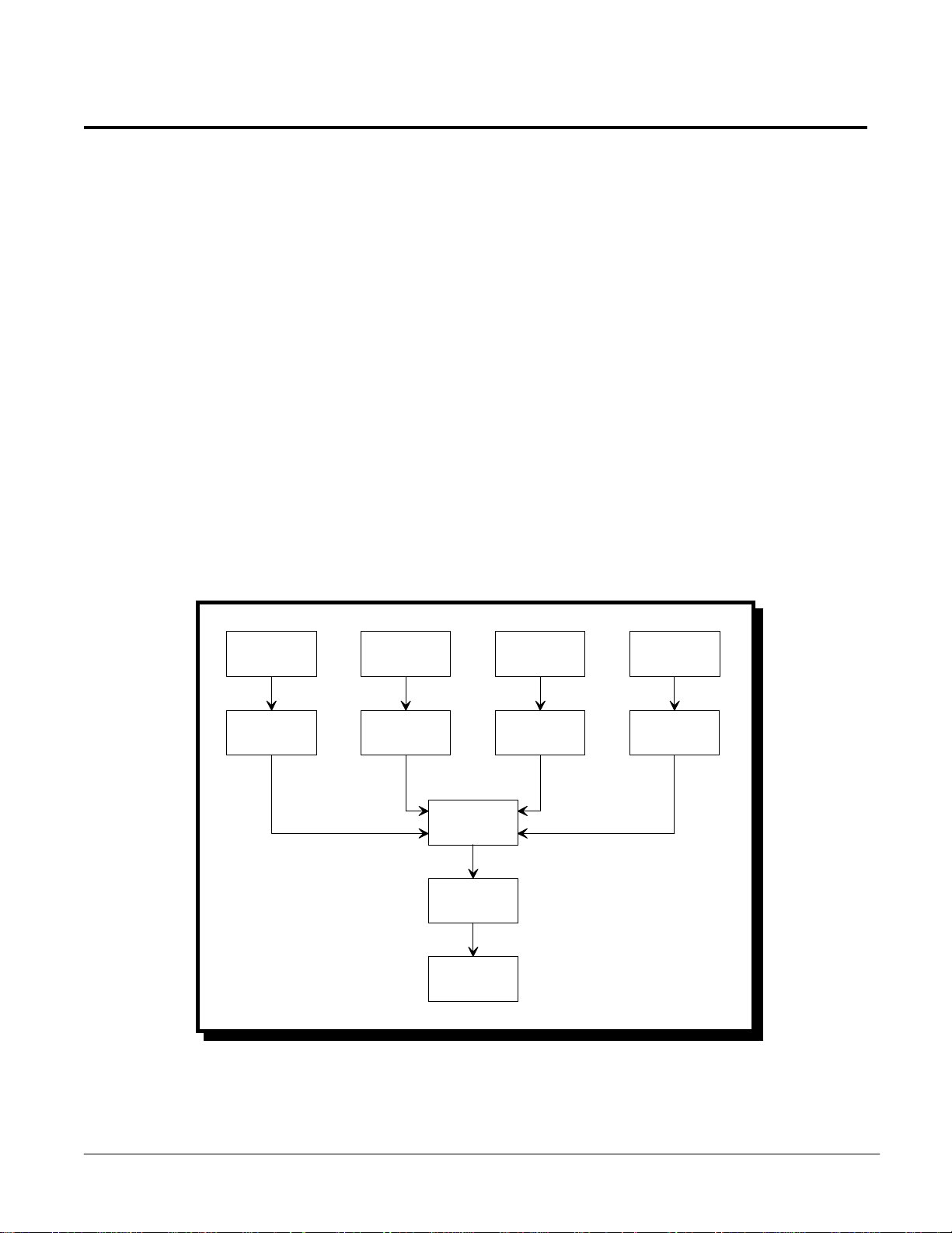
1.1 Functional Description
The SignalPro signal conditioning system covers a wide range of transducers and
applications, ye t most of the modul es shar e some common elements. F i gur e 1-1 shows a bl ock
diagram of a typical data acquisition system using SignalPro series signal conditioning
modules.
Transducer
Signal
Conditioner
Transducer
Signal
Conditioner
Multiplexer
ADC
Computer
Transducer
Signal
Conditioner
Transducer
Signal
Conditioner
Figure 1-1. SignalPro Data Acquisition System Block Diagram
Page 12

1.1.1 Transducers
The SignalPro series includes signal conditioning modules that enable the user to create data
SignalPro Series Users Manual 12
acquisition systems for transducers such as thermocouples, resistance temperature detectors
(RTDs), strain gages and accelerometers. Multiple transducers can be attached to a single
module, the number of which depends on the specific module selected.
1.1.2 Signal Conditioner
The electri ca l output signal generated b y a transducer of te n nee d s “conditioni ng ” b e f or e it can
be measured by an ADC. The signal may require amplification, filtering, linearization and
more before the ADC can accurately read it. Additionally, some transducers require an
excitation source or proper bia sing to complete me asurements. The Signal Pro syste m provid es
the transducer with any required excitation or biasing and performs all necessary
conditioning of the electrical output signal.
1.1.3 Multiplexer
SignalPro ser ies modul es can pr ovide up to 16 cha nnels of tr ansducer input b y mul tipl exi ng a
single main analog-to-digital (A/D) channel off the data acquisition adapter in the host
computer. The mul tiplexers on a SignalPro seri es module work like a switch, scanning each
transducer input channel and connecting the input to the selected main A/D channel.
The multipl exed input channels on the SignalPro modul e may be mapped back to any main
A/D channel on the data acquisition adapter in the host computer via jumper configuration.
Some modules provide less than 16 input channels, yet allow multiple modules to share a
single main A/D channel. For example, the QTC-250 RTD signal conditioning module has
eight input channels. Two QTC-250 modules may share one main A/D input channel to
provide 16 transducer input channels per main A/D channel. Multiplexing of all 16 main
A/D channels, (provided the A/D adapter type supports 16 channels), from the host
computer data acquisition adapter results in a maximum of 256 A/D transducer input
channels (16 x 16) per adapter.
1.1.4 Analog-to-Digital Converter (ADC)
The analog output si gnal from the tra nsducer is converted to di gital inf ormation by the ADC
in the data acquisition adapter in the host computer. Omega offers a complete line of data
acquisition adapters with both 12 and 16 bit resolution.
Page 13
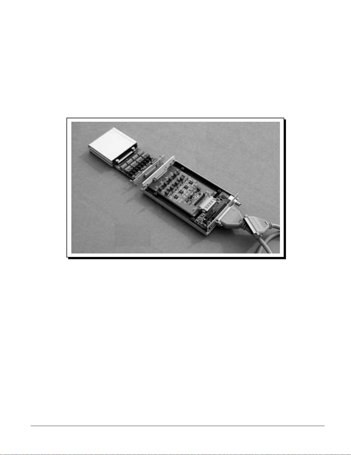
1.2 Hardware Description
SignalPro series modules come in several configurations. The QTC-100 is a self-contained
SignalPro Series Users Manual 13
power adapter module. The QTC-350 and QTC-450 are self contained interface boards with
BNC connectors. The remaining modules consist of two circuit boards: an interface board and
a removable terminal board. The interface boards are standard 3U size and easily mount in
the QTE-7 (seven modules), QTE-14 (fourteen modules) or QTC-xxx-PCS (one module) data
acquisition enclosures. The SignalPro terminal boards contain the transducer input screw
terminal blocks and most of the user configurable switches and jumper blocks. Figure 1-2
depicts a two board configuration with a single module data acquisition enclosure.
Terminal Box
QTC-250 Terminal Board
QTC-250 Interface Board
QTC-250-PCS Enclosure
SignalPro Series
Portable Signal Conditioning
System
Figure 1-2. SignalPro Portable Signal Conditioning System (QTC-250-PCS)
1.2.1 Interface Board Description
SignalPro i nterface board s operate with the following transducers and sensor s: thermocouple
(QTC-200/200T), RTD (QTC-250/250T), strain gage (QTC-300/300T), accelerometer
(QTC-350), voltage/current (QTC-400/400T) and analog signal filter (QTC-450). The
QTC-500/500T is a multipurpose interface board that provides isolated input signals utilizing
5B modules. The SignalPro DC voltage adapter module, QTC-100, provides a versatile means
to power signal conditioning modules mounted in the QTE-7 half rack housing unit using
automobile battery power. After the initial configuration and mounting of an interface circuit
board, it rarely requires removal from the QTE-7, QTE-14 or QTC-xxx-PCS enclosure. For
information on interface board data acquisition enclosures, see Chapter 2: SignalPro Series
Racks and Enclosures.
Page 14

1.2.2 Terminal Board Description
SignalPro series modules QTC-200, 250, 300, 400 and 500 use the removable terminal board to
8
QTC-500
4
QTC-450
16
QTC-400
4
QTC-350
4
QTC-300
8
QTC-250
14
QTC-200
Number of Expansion
Signal Conditioning Module
SignalPro Series Users Manual 14
facilitate the quick connection of transducer lead wires. Lead wires easily attach to the screw
blocks on the portable terminal board. SignalPro series terminal boards slide into their own
protective enclosur e which connects externally to the inte rface board and is secur ed with two
thumb screws.
1.3 Hardware Configuration
For the purpose of this discussion, it is presumed the user is configuring the SignalPro signal
conditioning system using an Omega sixteen channel data acquisition adapter, product
number: DAQP-12 or DAQP-16 (PCMCIA) or DAQ-1201/02 (ISA).
1.3.1 Main A/D Channel Selection and Jumper Configuration
There are sixteen analog input channels on the main connector of a Omega data acquisition
adapter. Each analog input channel of the adapter can connect to either one signal
conditioning module or multiple modules of the same type and thus be expanded up to 16
signal condi tioning channel s. Th e number of mod ules that can be connected to a singl e analog
input channel varies depending on the number of expansion channels the specific module
supports. For example, the QTC-300 supports four expansion channels, so four modules can
be connected to one analog input channel (4 x 4 = 16). The QTC-250 supports eight expansion
channels, so two modul es can be connecte d to one anal og input channel (8 x 2 = 16 ). Ta ble 1-1
lists available expansion channels.
Channels Supported
Table 1-1. Expansion Channel Availability
SignalPro series modules can occupy any analog input channel on the data acquisition
adapter. Which channel the module(s) will occupy is dependent on the configuration of the
main A/D channel selection jumper. Note that if multiple modules occupy the same main
A/D channel, then each module must have the same jumper setting. Figure 1-3 depicts the
main A/D channel selection jumper. The factory default setting is channel zero (CH0) for all
SignalPro series modules installed in the QTC-xxx-PCS portable data acquisition enclosure.
For modules installed in the QTE-7 and QTE-14 rack enclosures, the factory default setting for
the main A/D channel jumper will vary depending on the number of modules in each system.
See section 1.3.3 for a system configuration example.
Page 15
Main A/D C hannel Selection J umper
J1
QTC-500
J11
QTC-450
SignalPro Series Users Manual 15
CH0
CH1
CH2
CH3
CH4
CH5
CH6
CH7
CH8
CH9
CH10
CH11
CH12
CH13
CH14
CH15
Figure 1-3. SignalPro Series Main A/D Channel Selection Jumpers
The numerical designator for the main A/D channel jumper block varies from module to
module. Table 1-2 lists the designator for each specific module.
Signal Conditioning Module
Main A/D Channel
Jumper Designation
J1QTC-200
J10QTC-250
J5QTC-300
J15QTC-350
J1QTC-400
Table 1-2. Main A/D Channel Jumper Block Designators
1.3.2 Board Selection Jumper Configuration
Board selection jumper configuration options vary from module to module depending on the
number of expansion channels the module will support. Figure 1-4 depicts the board selection
jumpers with factory default settings and the numerical designator for each jumper block.
Note the factory default for all board selection jumpers is the lowest board number.
Page 16
SignalPro Series Users Manual 16
Board Selection Jumper Configurations
QTC-250
QTC-300
(J9)
BD0
BD1
(J6)
BD0
BD1
BD2
BD3
QTC-500
QTC-350/450
(J2)
BD1
BD2
(J14/J9)
BD1
BD2
BD3
BD4
Figure 1-4. SignalPro Series Board Selection Jumpers
When configuri ng multiple Signa lPro modules to one main A/D channel, the position of the
board selection jumper will determine which module is connected to a specific numerical
section of the sixteen available expansion channels. For example, if two QTC-250 modules
were connected to one main A/D channel, the first QTC-250 module would use the “BD0”
configuration and would occupy expansion channels 0 - 7. The second QTC-250 module
would use the “BD1” configuration and would occupy expansion channels 8 - 15.
1.3.3 Expansion Channel Numbering
Figure 1-5 depicts the logical channel numbering for a signal conditioning system in which
four main A/D channels from the host computer data acquisition adapter are expanded. (The
QTC-200 module actually only has fourteen data acquisition channel s. Channels one and two
are utilized for cold junction and offset information).
Page 17
QTC-200/QTC-250/QTC-300/QTC-300/QTC-300/QTC-300/QTC-350
SignalPro Series Users Manual 17
10
11
12
13
14
15
CH0
0
1
2
3
4
5
6
7
8
9
QTC-200
16
17
18
19
20
21
22
23
BD0
QTC-250
24
25
26
27
28
29
30
31
32
33
34
35
36
37
38
39
CH1
QTC-300
QTC-300
QTC-300
QTC-300
CH2
40
41
42
43
BD0
BD1
BD2
BD3
To Data Acquisition
adapter: DAQ P-12/16
or DAQ-1201/1202
QTE-7
015
44
45
46
47
48
CH3
Main A/D channels
unused. Channels 4 - 15
not multiplexed into
subchannels.
QTC-350
BD0
One QTC-200: 14 channels thermo couple input
One QTC -250: 8 channels RTD input
Four QT C-300s: 16 ch an nels strain gage input
One QTC -350: 4 channels acceler ometer i n put
49
50
51
52
53
54
55
Figure 1-5. Expansion Channel Numbering in a Multiple Module System
Page 18
2 SignalPro™ Series Racks and Enclosures
Enclosure Features
SignalPro Series Users Manual 18
Flexibility to combine multiple types of modules in a single unit
Ruggedized aluminum, metal, and plastic enclosures
External trigger source input with BNC connector
Compatible with all SignalPro Series modules
Multiple enclosures can be linked together using only one data acquisition adapter for
up to 256 channels in a system.
Power can be supplied by a flexible range of either AC or DC voltage with appropriate
options installed
The SignalPro series interface boards are a standard 3U size and mount easily into the QTE-7,
QTE-14 or QTC-xxx-PCS data acquisition enclosures. Each of these enclosures is equipped
with a DIN -48 female connector(s) to mate with the interf ace boards and a standar d Omega
D-37 data acquisition connector which mates with the data acquisition adapter in the host
computer.
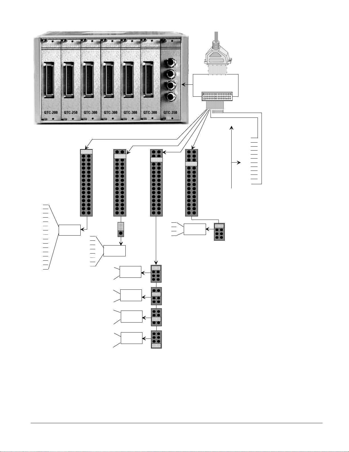
There are three housing options a vailable for Si gnalPro modules: (1) the QTE-14 rack mount
enclosure which holds up to 14 modules, (2) the QTE-7 half rack enclosure which holds up to
7 modules and (3) the QTC-xxx-PCS portable unit which accommodates a single module. (See
Figure 2-1).
QTE-7
QTC-xxx-PCS
QTE-14
Figure 2-1. SignalPro Series Data Acquisition Racks and Enclosures
Page 19
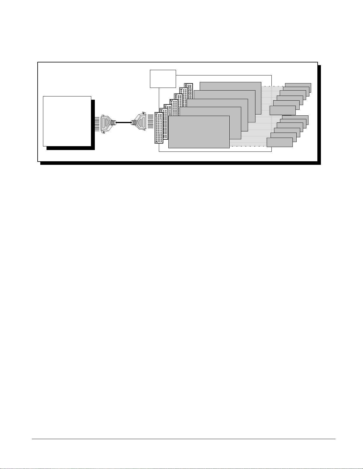
2.1 Multiple Module Enclosures
Figure 2-2 shows the block diagrams for the QTE-7 and QTE-14 data acquisition enclosures.
SignalPro Series Users Manual 19
Data
Acquisition
Adapter
Power
Module
QTC-200
QTC-250
QTC-350
QTC-500
QTE-7 / QT E -14
QTC-200
QTC-200
QTC-200
QTC-200
QTC-300
QTC-400
QTC-450
QTC-300
QTC-300
......
QTC-300
QTC-300
Sensor
Sensor
Figure 2-2. Multiple Module Enclosure Block Diagram
SignalPro modules may be mounted into any slot in the data acquisition enclosures. (The
QTC-100 power adapter module will only mount in the first slot of the QTE-7 and are not
available for the QTE-14).
2.2 External Connections
2.2.1 Data Acquisition Adapter Connection
Each of the SignalPr o series enclosures is equipped with a D-37 female connector that is pin
compatible with Omega data acquisition adapters. Omega data acquisition adapters are
available with 12 and 16 bit resolution.
2.2.2 External TTL Trigger Connector
The data acquisition adapter in the host computer requires an initial signal to start A/D
conversions. Depending on the software configuration, A/D conversions will be initiated by
either a software trigger or an external hardware trigger. Each of the SignalPro series data
acquisition enclosures provides a BNC connector for a hardware TTL trigger input. The TTL
trigger starts A/D conversions on either the rising or falling edge of a TTL signal. The BNC
connector maps the TTL input back to pin 25, (digital input channel 0), on the Omega D-37
data acquisition adapter.
2.2.3 Multiple Enclosures
Multiple SignalPro series enclosures can be linked together using only one data acquisition
adapter to expand a signal conditioning system from sixteen up to 256 channels. An Omega
D-37 adapte r cable, prod uct number: CP-D AQ, is requ ired to link multiple enclosures in your
system.
Page 20
2.3 Power Requirements
The QTE-7 and QTE -14 enclosures require an AC input voltage from 90 to 260 VAC @ 60 Hz.
5.22” (132.7mm)
9.39” (238.7mm)
17.68” (449.1mm)
QTE-14
5.22” (132.7mm)
9.39” (238.7mm)
9.28” (235.7mm)
QTE-7
1.56” (39.62mm)
8.78” (233.0mm)
5.57” (141.5mm)
QTC-xxx-PCS
Height
Depth
Width
SignalPro Enclosure
SignalPro Series Users Manual 20
With the QTE-7, the user has the option of using an Omega QTC-100 power module. The
power module allows the user to power a remote data acquisition system with automobile
battery power. The QTC-xxx-PCS requires a DC input voltage from 9 to 25 VDC and is
shipped with a 12v, 2.92A power supply module included.
All three enclosure models have a +5V and +/-15V DC power supply mounted inside the
enclosure to provide power for SignalPro series modules. The QTC-xxx-PCS internal power
supply automatically corrects the pola rity of the input vol tage to pr ovide maximum f lexi bility
in choosing a power source for the portable enclosure.
2.4 Physical Dimensions
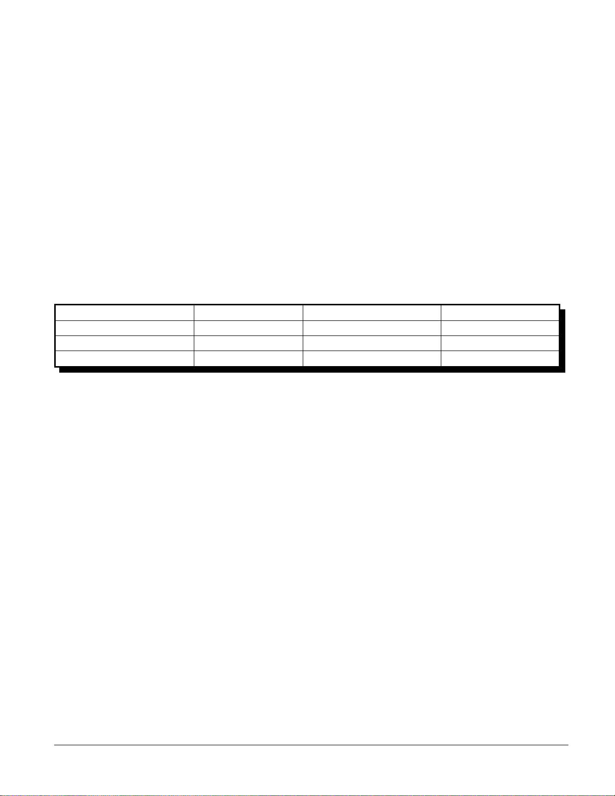
Table 2-1 lists the physical dimensions of each enclosure in the SignalPro series.
Table 2-1. Data Acquisition Enclosure Physical Dimensions
Page 21
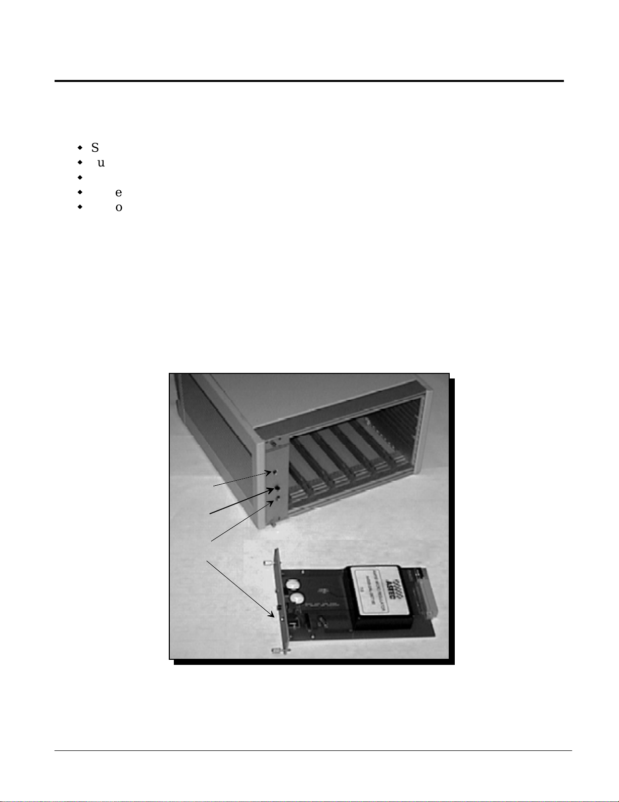
3 QTC-100 DC Voltage Power Adapter Module
QTC-100 Features
SignalPro Series Users Manual 21
Standard 3U interface board for use with the QTE-7 half-rack housing unit
Supplies 25 watts of total power to the QTE-7
No polarity required on the DC input voltage - Center pin can be positive or negative
Power LED to indicate slot status
Optional power cord allows system to be powered from a standard automobile
cigarette lighter
The QTC-100 is a DC voltage power adapter module which provides a convenient way to
power SignalPro series modules using an automobile battery. For use with the QTE-7
half-rack housing unit, the QTC-100 accepts DC input voltage from 10 to 28vdc and generates
the +5 and ±15vdc output require d to powe r a remote d ata acquisi tion syste m. An optional six
foot cord, ( product number: QTC-PWR-DC), is availa ble to al low the user to gene rate system
power using a standard automobile cigarette lighter. (See Figure 3-1).
Power
Indicator
Power
Switch
Input Jack
DC 9~28V
Figure 3-1. QTC-100 DC Voltage Power Adapter Module
QTC-100 DC Voltage
QTE-7
Power Adapter
Page 22
3.1 Circuit Board Description
The QTC-100 is a standard 3U size board designed for use with the QTE-7 half rack data
SignalPro Series Users Manual 22
acquisition enclosure. A block diagram of QTC-100 is shown in Figure 3-2. The DC to DC
converter accepts input voltage from 10 to 28vdc and in turn generates +5, +15 and -15vdc.
The 14-pin male power connector and the DIN-48 male connector on the QTC-100 interface
board will only connect to the first slot of the QTE-7.
14-Pin Power Connector
+5v, +/-15v
LED
Power
Switch
DC/DC
Converter
10~28 vdc
QTC-100
Figure 3-2. QTC-100 Block Diagram
3.1.1 AC/DC Power Supply Priority
With the QTC-100 DC Voltage Power Adapter Module, the QTE-7 half rack enclosure can
accept either AC power (90~260 vac) or DC power (9~28 vdc). If both power supplies are
available simultaneously, the QTE-7 will use AC power to generate the +5, +15 and -15VDC
power required for all SignalPro series modules in the QTE-7 system. If the AC power supply
is unavailable or failed, the QTE-7 will automatically switch to DC power from QTC-100
power module.
DIN-48
Connector
3.1.2 Power Jack and Switch
The QTC-100 power jack accepts 9~28vdc through a 2.5 x 5.5mm DC plug in which the center
pin can be either positive or negative. A push button switch on the front panel is used to
control power to the QTE-7 and a green LED indicates the power status. (Refer to Figure 3-1
for locations of the power jack, switch and indicator).
Page 23

3.2 QTC-100 Specifications
0.3 Kg
Weight:
100mm X 166.4mm
Dimension:
500 VDC
Isolation:
50mV p-p (+5V), 100mV p-p (+/-15V)
Noise/Ripple:
0.25% (+5V), 3% (+/-15V)
Load Regulation:
0.25% for +5V, 2% for +/-15V
Line Regulation:
+5V+/-1%@3.50A, +15V+/-3%@0.50A, -15V+/-3%@0.50A
Output Voltage:
25 Watts
Total Power:
<100 mA p-p 80-85% typical
Input Ripple Current:
No Polarity required (Center pin can be either positive or
Input Polarity:
Suitable for 2.5 x 5.5mm DC plug
Power Jack:
DIN-48 male and 14-pi n right angle male, mates with fi rst slot
Connectors:
SignalPro Series Users Manual 23
of QTE-7
negative)
Page 24
4 QTC-200 Thermocouple Input Module
QTC-200 Features
SignalPro Series Users Manual 24
Fourteen Thermocouple input channels
Up to 224 Analog Input Channels can be configured in a system
Thermocouple types J, K, T, E, S or R, N & B supported
On board Low Pass Filter for each channel (-80dB @ 50Hz)
Isolated Cold Junction Compensation
Terminal block for quick, easy signal connections
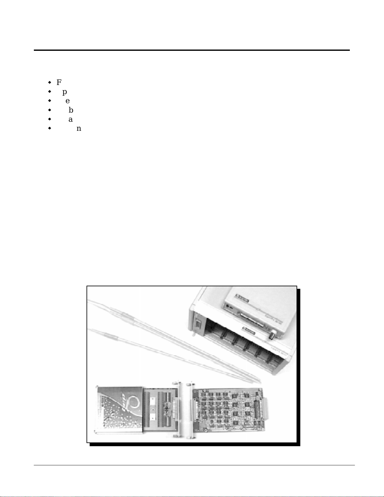
The QTC-200 is a fourteen channel thermocouple input module. Each channel is equipped
with a separate instrument amplifier, offset adjustment and low pass filter. Up to sixteen
QTC-200 modules can be configured in an Omega signal conditioning and data acquisition
system for a total of 224 analog input channel s. The QTC-200 can also be coupled with other
modules in Quatech’s SignalPro™ series to provide a versatile data acquisition system.
The QTC-200 module consists of two circuit boards: the QTC-200 interface board and the
QTC-200T terminal board. The interface board is a standard 3U size board which can be
mounted in the QTE-7, QTE-14 or QTC-200-PCS data acquisition enclosures. The QTC-200T
terminal board contains the thermocouple input screw blocks, Cold Junction Compensation
(CJC) sensor and the mode selection switches. This two board configuration allows quick and
easy connection of the thermocouple lead wires. After the initial configuration of the interface
board, it can be mounted in a data acquisition enclosure and will rarely require removal. All
connections are completed on the screw terminals of the portable QTC-200T, which is then
plugged into the interface board and secured using two thumb screws. (See Figure 4-1).
Thermocouple
Sensors
QTC-200 Terminal Board
Figure 4-1. QTC-200 Thermocouple Input Module
QTE-7
QTC-200 Interface Board
QTC-200-PCS
Page 25

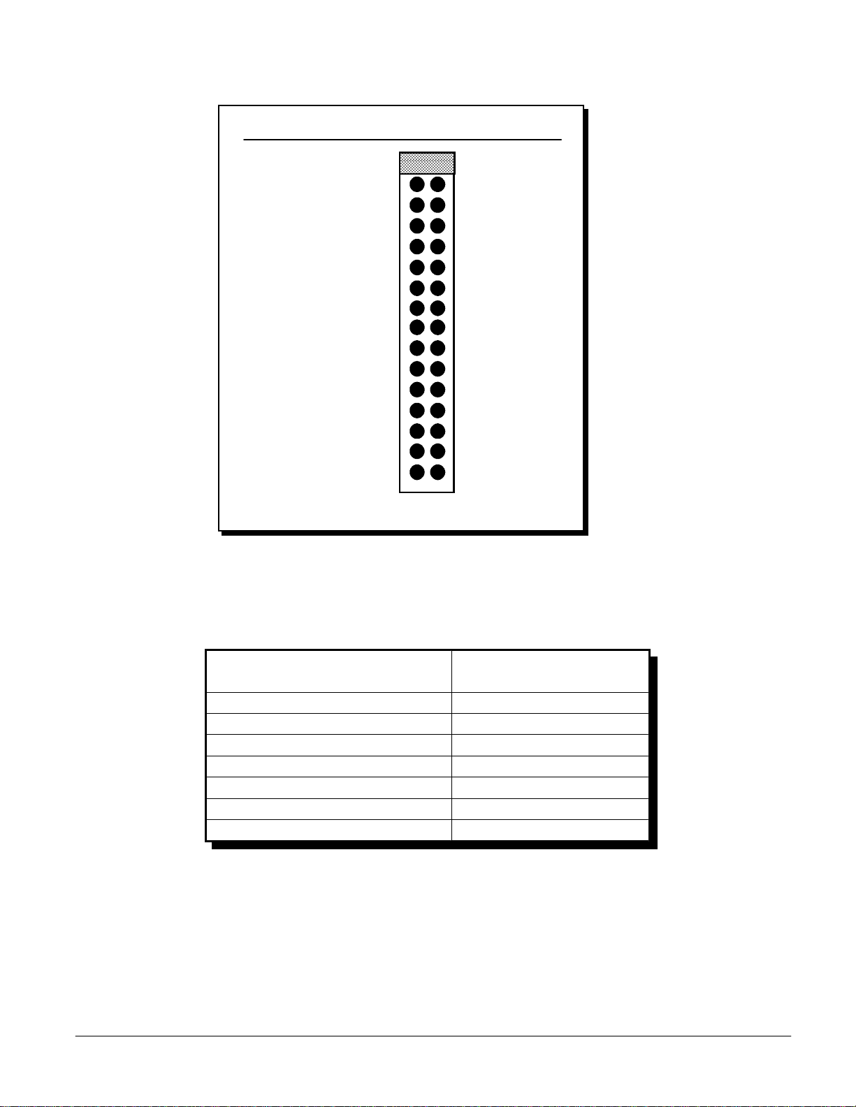
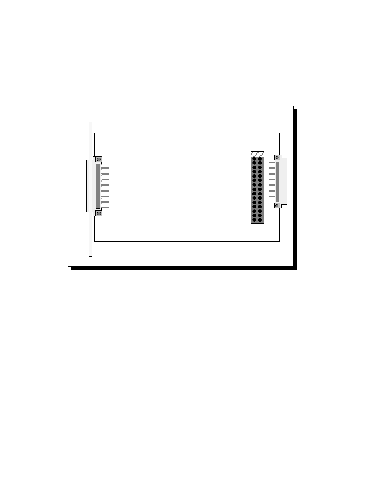
4.1 Circuit Board Description
SignalPro Series Users Manual 25
4.1.1 QTC-200 Interface Board Description
The QTC-200 interface board shown in Figure 4-1 can be mounted in SignalPro series data
acquisition racks and enclosures. (See Chapter 2 for information on SignalPro series racks).
Each rack enclosure i s equipped wi th a DIN-4 8 female connector which mate s to the QTC-200
and other SignalPro series signal conditioners. The rack also contains a standard Omega D37
connector which attaches to the host computer data acquisition adapter.
The QTC-200 provides sixteen channels; one channel for CJC input, one channel for zero offset
input and fourteen channels for thermocouple input; by multiplexing a single main A/D
channel off the host computer data acquisition adapter. The mul ti pl exer on the QTC-200 scans
the sixteen input channels sequentially and connects each input to the single main A/D
channel. The sixteen multiplexed input channels may be mapped back to any main A/D
channel on the data acquisition adapter depending on the configuration of jumper J1.
Multiplexi ng of all 16 main A/D channel s from the host computer results in a maximum of
256 channels consisting of 224 A/D input channels (14 x 16) and 32 CJC/zero offset input
channels (2 x 16) per data acquisition adapter.
4.1.2 QTC-200T Terminal Board Description
The QTC-200T terminal board contains the thermocouple input screw blocks and the mode
selection switches which configure either differential or single ended input for each channel.
The terminal board DIN-48 female connector plugs into the QTC-200 interface board and is
equipped with a strain relief bracket to secure external thermocouple wiring.
Page 26
4.2 Hardware Configuration
SignalPro Series Users Manual 26
For system configuration options see Chapter 1: SignalPro Series Overview, section 1.3:
Hardware Configuration.
4.2.1 QTC-200 Interface Board Configuration
QTC-200
Main A/D Channel
Selection Jumper J1
CH0
CH1
CH2
CH3
CH4
CH5
CH6
CH7
CH8
CH9
CH10
CH11
CH12
CH13
CH14
CH15
Figure 4-2. QTC-200 Main A/D Channel Jumper Block Location
Figure 4-2 shows the location of the main A/D channel selection jumper block J1. System
configuration options for J1 are discussed extensively in Chapter 1, section 1.3
4.2.2 QTC-200T Terminal Board Configuration
Figure 4-3 depicts the location of the thermocouple input screw blocks, differential or
single-ended mode selection switches (SW1 and SW2), CJC sensor and the thermocouple lead
wire strain relief bracket.
Page 27
ST1
SignalPro Series Users Manual 27
TC8
TC7
TC6
TC5
TC4
TC3
TC2
-
+
CJC
Sensor
-
+
-
+
-
+
-
+
-
+
-
+
TC9
TC10
TC11
TC12
TC13
TC14
TC15
-
+
-
+
-
+
-
+
-
+
SW2
-
+
-
+
QTC-200T
Figure 4-3. QTC-200T Terminal Board
SW1
O
N
1 2 3 4 5 6 7 8
O
N
1 2 3 4 5 6 7 8
4.2.2.1 Thermocouple Input Mode Selection Switches
Figure 4-4 depicts the mode selection switches for thermocouple input channels 2 through 15.
12345678
Thermocouple
12345678
Switch OFF (Open) - - - Differential Input
Switch ON (Closed) - - - Single Ended
All Switches shown with factory default setting:
OFF (Differential Input)
ON
ON
CH15
CH14
CH13
CH12
CH11
CH10
CH9
CH8
CH7
CH6
CH5
CH4
CH3
CH2
CH1
CH0
OFFSET
CJC
Figure 4-4. Thermocouple Input Mode Selection Switches
Page 28

4.3 Basic Principles
Thermocouples measure temperature using the Seebeck Effect which occurs at the junction
SignalPro Series Users Manual 28
connection of two dissimilar metals. A voltage difference is generated at the junction that
changes with temperature over a given range. This voltage is not a linear function of
temperature and theref ore cannot be rela ted dir ectly to temperature. Linear ization table s and
polynomial appr oximation are two methods used to transform thermocouple input into real
temperature measurement.
One problem experienced with thermocouple temperature measurement is when the junction
between thermocouple lead wires and terminal blocks creates, in essence, another
thermocouple. The QTC-200 signal conditioning module provides a practical solution to this
problem by using a built in cold junction compensation circuit to neutralize the voltage
created at the terminal block junction.
Damaged thermocouples can introduce another significant source of measurement error by
becoming open or extremely resistive. The QTC-200 si gnal conditioning modul e uses an open
thermocouple detection circuit on each thermocouple input to guard against this possibility.
The detection circuit drives a low level current through the thermocouple causing the input
amplifiers to be driven to rails whenever an open or highly resistive thermocouple is present.
4.3.1 Cold Junction Compensation (CJC) Sensor
The QTC-200T uses an isolated CJC sensor to detect temperature at the thermocouple
terminals with high accuracy and minimize any temperature difference between the CJC
sensor and thermocouple terminal junctions.
The first channel (CH0) is used to measure temperature at the CJC sensor.
Temperature in °C : TC and in °F : TF is calculated as follows:
TC = - 273
(A+Bln(R)+C(ln(R))
1
3
)
R = VCH0 * 5000 / (10 - VCH0)
TF = Tc * 9 / 5 + 32
where A=0.00128974451631 VCH0: Voltage reading at CH0 in volts
B=0.00023530184288 R: Resistance of the sensor in ohms
C=0.00000009729702
Page 29

4.3.2 Software Zero Correction
SignalPro Series Users Manual 29
Since most thermocouple signals are within the 100mV range, offset voltage between the
QTC-200T and the data acquisition adapter must be monitored. QTC-200 channel 1 (CH1) is
used to check the zero reference of the QTC-200T, then the data acquisition system software
subtracts this offset.
4.3.3 Single Ended Thermocouple Measurements
A single ended thermocouple measurement is shown in Figure 4-5. The thermocouple input
channel must be configured for single ended operation as discussed in section 4.2.2.1 of this
chapter.
ST1
GND
+
+
Thermocouples
Strain Relief
Bracket
Thermocouple
Terminal Block
Figure 4-5 Single Ended Thermocouple Measurement
4.3.4 Differential Thermocouple Measurements
A differential thermocouple measurement is shown in Figure 4-6. The thermocouple input
channel must be configured for differential operation as discussed in section 4.2.2.1 of this
chapter.
ST1
Wire Shield
GND
-
Thermocouple
Strain Relief
Bracket
+
Thermocouple
Terminal Block
Figure 4-6. Differential Thermocouple Measurement
Page 30

4.4 QTC-200/QTC-200T Specifications
SignalPro Series Users Manual 30
Connector: DIN-48 male, mates with QTE-7, QTE-14 and QTC-200-PCS
Signal Connection: DIN-48 female, mates with terminal block
Number of TC Channels: 14 (CH0: CJC; CH1: Zero offset; CH2-15: Thermocouple inputs)
Input Type: Differential/Single-ended ( DIP Switch Select-able)
Precision Thermistor: 5000 Ohm @ 25 °C
Supported Thermocouple Type, Temperature Range
Type
J Thermocouple: -200°C to 760°C
K Thermocouple: -100°C to 1350°C
T Thermocouple: -200°C to 400°C
E Thermocouple: -200°C to 1000°C
S or R Thermocouple: 0°C to 1760°C
N Thermocouple: 0°C to 1300°C
B Thermocouple: 0°C to 1800°C
Voltage Input Range: ±100 mVDC
Maximum Input Voltage: -20V to +15V DC
Input Bias Current: 6 nA typ
Input Offset Voltage: ± 0.07 mV typ, ± 0.25 mV max (Adjustable to zero)
Range
Input Offset Drift: ± 0.4 lV/°C typ, ± 2.0 lV/°C max
Gain Range: 100 fixed
Gain Error: X100
Input Impedance: 12 GW
Gain Nonlinearity : X100
Gain Error Drift: X100
Common Mode Rejection: X100
Cutoff Frequency (-3dB): 5 Hz (4 Poles Butterworth, -3dB@5Hz, -80dB@50Hz)
Page 31

Dimension: 160mm X 100 mm for QTC-200;
SignalPro Series Users Manual 31
100mm X 100mm for QTC-200T
Weight: QTC-200 0.29Kg;
QTC-200T (with enclosure): 0.36Kg
Power Consumption: +5V/20mA typ; +15V/40mA typ; -15V/40mA typ
Temperature Range: 0 ~ +70°C
Page 32

5 QTC-250 RTD Signal Conditioning Module
QTC-250 Features
SignalPro Series Users Manual 32
Eight channel Resistor Temperature Detector (RTD)
On board low-pass filter for each channel (-80dB @ 50Hz)
Per channel jumper selectable excitation current source of 1mA, 0.5mA or 0.25mA
Supports 2, 3 and 4 wire RTD configurations
Up to 256 channels can be configured in a system
Terminal block for quick, easy signal connections
The QTC-250 is an eight channel Resistance Temperature Detector (RTD) input signal
conditioning module. Each channel is equipped with separate instrument amplifiers, three
excitation cur rent source options and a fourth ord er low pass f ilter . Up to thirty- two QTC-250
modules can be configured in an Omega signal conditioning and data acquisition system for a
total of 256 analog input channels. The QTC-250 can also be coupled wi th other modules in
Omega’s SignalPro™ series to provide a versatile data acquisition system.
The QTC-250 module consists of two circuit boards: the QTC-250 interface board and the
QTC-250T terminal board. The interface board is a standard 3U size board which can be
mounted in the QTE-7, QTE-14 or QTC-250-PCS data acquisition enclosures. The QTC-250T
terminal board contai ns the RTD i nput screw bl ocks, channel gain sel ect switches and channel
excitation current sources. T his two board configuration allows qui ck and easy connection of
the RTD lead wires. After the initial configuration of the interface board, it can be mounted in
a data acquisition enclosure and will rarely require removal. All connections are completed on
the screw terminals of the portable QTC-250T, which is then plugged into the QTC-250
interface board and secured using two thumb screws. (See Figure 5-1).
QTC-250T
Terminal Block
Figure 5-1. RTD Signal Conditioning Module
QTC-250-PCS
QTE-7
QTC-250
Interface Bo a rd
Page 33

5.1 Circuit Board Description
5.1.1 QTC-250 Interface Board Description
SignalPro Series Users Manual 33
The QTC-250 interface board shown in Figure 5-1 can be mounted in SignalPro series data
acquisition racks and enclosures. (See Chapter 2 for information on SignalPro series racks).
Each rack enclosure i s equipped wi th a DIN-4 8 female connector which mate s to the QTC-250
and other SignalPro series signal conditioners. The rack also contains a standard D37
connector which attaches to the host computer data acquisition adapter.
Eight RTD input channels are provided by multiplexing a single main A/D channel off the
host computer data acquisition adapter. The multiplexer on the QTC-250 scans the eight RTD
input channels sequentially and connects each input to the single main A/D channel. The
eight multipl exed input channe ls may b e mapped back to any main A/D channel on the data
acquisition adapter depending on the configuration of jumper J10. Two interface boards may
share one single ended A/D input from the host computer to provide a maximum of 16
multiplexed channels per main A/D channel. Multiplexing of all 16 main A/D channels from
the host computer results in a maximum of 256 A/D input channels, (16 x 16), per data
acquisition adapter.
5.1.2 QTC-250T Terminal Board Description
The QTC-250T terminal board shown in Figure 5-2 contains the input terminal blocks,
excitation current sources and input gain amplifiers for each of the eight RTD inputs. The
terminal board DIN-48 female connector plugs into the QTC-250 interface board and is
equipped with a strain relief bracket to secure external RTD wiring.
ST1
IRR+
I+
IRR+
I+
IRR+
I+
IRR+
I+
IRR+
I+
IRR+
I+
IRR+
I+
IRR+
I+
J8 - RTD8
J7 - RTD7
J6 - RTD6
J5 - RTD5
J4 - RTD4
J3 - RTD3
J2 - RTD2
J1 - RTD1
Figure 5-2. QTC-250T Terminal Board
Page 34

5.2 Hardware Configuration
For system configuration options see Chapter 1: SignalPro Series Overview, section 1.3:
SignalPro Series Users Manual 34
Hardware Configuration.
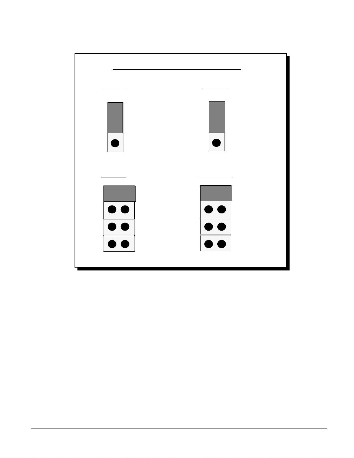
5.2.1 QTC-250 Interface Board Configuration
Figure 5-3 depicts the location of the main A/D channel and board selection jumpers (J9/J10).
System configuration options for J9 and J10 are discussed extensively in Chapter 1, section 1.3.
Board Selection Jumper
J9
Main A/D Channel
Selection Jumper J10
Figure 5-3. QTC-250 Interface Board Jumper Locations
5.2.2 QTC-250T Terminal Board Configuration
The QTC-250T terminal board contains the excitation current selecti on jumpers and the input
gain selecti on switches for each of the eight RTD inputs. The user must configur e two settings:
Input gain (GAI N) and ex citati on current source (I ). The gai n and curre nt source settings are
determined according to the following two considerations:
I * RRTDMAX * GA IN shoul d b e as cl ose as possi ble to, bu t not ex ceed , the f ull scale value of
10 Volts, where RRTDMAX is the maximum RTD r esistance in the specific measuring rang e.
The excitation current “I” should be the smallest possible value, (0.25mA, 0.5mA or 1.0mA),
that will satisfy the first consideration.
Note that resistive heating must be consider e d w he n determining the excitati on current source
amplitude. The RTD dissi pates power at the ra te of Power = I x R, where I is the excitati on
2
current and R is the RTD resi stance. The heat genera ted by the excitation cur rent through the
RTD is a source of error in temperature measurements. Since lower current options will
generate less heat, a combination of low current with a high A/D input gain is desirable.
Page 35

Table 5-1 lists the suggested gain and excitation current values for all supported RTD types.
9.81
10
0.25 mA
1133.158/ 3922.784
-100 to 200
1,816.81(0.00527)
9.81
10
0.5 mA
566.576 / 1961.381
-100 to 200
908.4 (0.00527)
6.51
10
0.5 mA
372.789 / 1301.86
-100 to 200
604 (0.00518)
9.51
100
0.25 mA
66.6 / 380.31
-80 to 260
120 (0.00672)
5.58
100
0.25 mA
69.528 / 223.221
-60 to 180
100 (0.00618)
1.91
100
1.0 mA
5.128/ 19.116
-100 to 260
9.035 (0.00427)
7.84
10
0.25 mA
185.201 / 3137.08
-200 to 600
1,000 (0.00385)
7.84
10
0.5 mA
92.6 / 1568.54
-200 to 600
500 (0.00385)
7.47
10
0.5 mA
79.881 / 1494.393
-200 to 600
470 (0.00392)
6.27
10
1.0 mA
37.04 / 627.416
-200 to 600
200 (0.00385)
9.39
100
0.25 mA
18.52 / 375.704
-200 to 800
100 (0.00385)
8.36
100
1.0 mA
4.334 / 83.575
-200 to 630
25.5 (0.00392)
Full
Gain
Excitation
Resistance
Temperature
RTD Types
SignalPro Series Users Manual 35
W @0°C(a)
1
Platinum
Copper
Nickel
Range
(°C)
Range
(W )
Current
mA
Setting
2
Scale
Output
(Volts) 3
Nickel-Iron
Notes:
1. (a) is the temperature coefficient in W / W / º C .
2. The gai n setting li sted in Ta ble 5-1 is the hardw are setting f or each supported RTD sensor.
If using DaqEZ, the QTC-250 module gain should be set to 1. The hardware configuration,
(gain and current settings), for each RTD channel will be determined by the DaqEZ signal
conditioner database.
3. The full scale output is from the QTC-250 to the data acquisition card.
5.2.2.1 A/D Gain Selection Switches
The A/D input gain for each of the RTD inputs is individually selectable using SW1 and SW2
as shown in Figure 5-4. Each of the input amplifiers can be configured for gains of x1, x10 or
x100. Configuring the gain setting on the QTC-250T terminal board input amplifiers will
result in less signal noise than using the A/D configuration options available on the data
acquisition adapter in the host computer.
Table 5-1. Suggested Gain and Excitation Current Values for Supported RTD Types
Page 36

SW1
SignalPro Series Users Manual 36
12345678
ON
RTD5
SW2
12345678
ON
RTD1
Gain = X1
(factory default)
RTD6
RTD7
RTD8
Gain = X10 Gain = X100
RTD2
RTD3
RTD4
Figure 5-4. A/D Gain Selection Switches
5.2.2.2 Excitation Current Selection Jumpers
The QTC-250T provides a stable, constant current source for each of the eight RTD input
channels. The excitation current value of 1.0mA, 0.5mA or 0.25mA for each channel can be
selected using jumper blocks J1 through J8 as shown in Figure 5-5.
RTD Exci tation Current Sele cti on J umpe r s
J1 - J8
(configures RTD1 - RTD8 respectively)
1.0 mA
(factory default)
0.5 mA
0.25 mA
Figure 5-5. Excitation Current Selection Jumpers
Page 37

5.3 RTD Measurements
SignalPro Series Users Manual 37
5.4 Basic Principles
The basic principle behind RTD measurements is that resistance of an RTD increases with
temperature. By supplying the RTD with a constant current source and measuring the voltage
drop across the RTD, the change in resistance can be monitor ed. The re lationship betw een the
change in temperature and the change in RTD resistance can be defined as follows:
∆T→∆R = ∆V ÷ I
RTD RTD
where:
∆T = the change in temperature
∆R = the change in RTD resistance
RTD
∆V = the voltage drop across the RTD
RTD
I = the RTD excitation current source value
Note: RTD resistance is measured in units of voltage or current where the current amplitude
from the QTC-250 is constant.
5.4.1 Two-Wire RTD Measurements
The configuration of a two-wire measurement circuit is shown in Figure 5-6. The RTD
resistance in this circuit is read at the current source. If the lines connected to the RTD are
short, this method may b e acceptable. H owever, this method is g enerally inaccur ate since the
resistance and thermal heating characteristics of long lead wires ( ) connected to the RTD
R
line
introduce some measurement error.
R
line
I R I +
RTD
Excitation
Current
R +
R
line
Strain Relief
Bracket
RTD
Terminal Block
Figure 5-6. Two-Wire RTD Measurement
Page 38

5.4.2 Three-Wire RTD Measurements
SignalPro Series Users Manual 38
The configuration of a three-wire measurement circuit is shown in Figure 5-7. T he advantage
of this circui t over the two-wire method i s the elimination of one current car rying lead w ire.
However, the resistance and thermal heating characteristi cs of the remaining lead wir e (R )
line
to the RTD may still introduce some measurement error.
R
line
I -
RTD
Excitation
Current
R I +
R
R
line
line
Strain Relief
Bracket
RTD
Terminal Block
R +
Figure 5-7. Three-Wire RTD Measurement
5.4.3 Four-Wire RTD Measurements
The configuration of a four-wi re measurement circuit is shown in Figure 5-8. The advantage
of this circuit over the previous two and three-wire methods is that greater accuracy is
obtained. By measuring the change in the RTD voltage d rop directly at the RTD resistor, the
error introduced from the lead wires (R ) to the RTD is removed. The measurement error
introduced due to resistance of the A/D lead wires (R ) is insignificant. The input
line
lead
impedance of the A/D is very high and thus minimizes current flow through the lead wires.
R
line
R
line
I -
RTD
Excitation
Current
R I +
R +
R
line
R
line
Strain Relief
RTD
Terminal Block
Bracket
Figure 5-8. Four-Wire RTD Measurement
Page 39

5.5 QTC-250/QTC-250T Specifications
Connector: DIN-48 male, mates with QTE-7, QTE-14, and QTC-250-PCS
SignalPro Series Users Manual 39
Signal Connection: DIN-48 female, mates screw terminal block for easy connection
Number of Channels: 8
RTD type: Platinum 25.5W, 100W, 200W, 470W, 500W, 1000W
Copper 10W
Nickel 100W, 120W
Nickel-Iron 604W, 908.4W, 1816.81W
Accuracy and Resolution:
Type
100 W Platinum -100°C to +600°C 0.4 °C 0.3 °C/ 0.1 °C
120 W Nickel 0°C to 260°C 0.15 °C0. 3 °C/ 0.1 °C
Excitation Current: 1.0 mA, 0.5mA, 0.25 mA
Output Impedance: 1990K Compliance: 10V
Range Accuracy Resolution(12-bit/16-bit)
RTD Configuration: 2-wire, 3-wire, 4-wire
Input Type: Differential
Voltage Input Range: ±10 V
Input Bias Current: ±0.5 pA typ; ±2 pA max
Input Offset Voltage: ± (0.01+0.02/G) mV typ, ± (0.05+0.1/G) mV max
(Adjustable to zero)
Input Offset Drift: ± (0.1+0.5/G) lV/°C typ, ± (0.25+100/G) lV/°C max
Gain Range: 1, 10, 100
Gain Error: X1 0.005% typ, 0.024% max
X10, X100 0.01% typ, 0.024% max
Input Impedance: 10 GW
Gain Non linearity : X1,X10, X100 ± 0.0004% of FS typ, ± 0.001% of FS max
Gain Temp. Coefficient: X1, X10, X100 ± 2.5 ppm/°C typ, ± 10 ppm/°C max,
Page 40

Common Mode Rejection: X1 80 dB min 99 dB typ
X10 96 dB min 114 dB typ
SignalPro Series Users Manual 40
Cutoff Frequency: 5 Hz (4 Poles Butterworth, -3dB@5Hz, -80dB@50Hz)
Power Requirement: + 5V ±5% 70mA typ
Dimension: 160mm X 100mm for QTC-250; 100mm X 100mm for QTC-250T
Weight: 0.13Kg for QTC-250; 0.35Kg for QTC-250T.
X100 110 dB min 123 dB typ
+15V ±5% 50~70mA typ
-15V ±5% 50mA typ
Page 41

6 QTC-300 Strain Gage Input Signal Conditioning Module
QTC-300 Features
SignalPro Series Users Manual 41
Four Strain Gage input channels (Up to 256 channels can be configured in system)
Custom configurable excitation current source which readily converts to vendor
specified Strain Gage Excitation Voltage
Supports full, half and quarter bridge gage configurations
On board low-pass filter for each channel (10Hz, 100Hz or 1KHz cut off frequency)
Easy zero and shunt calibration
Terminal block for quick, easy signal connections
The QTC-300 is a four channel strain gage input signal conditioning module. Each channel is
equipped wi th separate instrument ampl ifiers, multiple excitati on current source options and
a fourth order low pass filter. Up to 64 QTC-300 modules can be configured in an Omega
signal condi tioning and data acquisiti on system for a total of 256 analog input channels. Each
channel has selectable gain of 1, 10, 100, 200 or 500. The QTC-300 can also be coupled with
other modules in Omega’s SignalPro series to provide a versatile data acquisition system.
The QTC-300 module consists of two circuit boards: the QTC-300 interface board and the
QTC-300T terminal board. The interface board is a standard 3U size board which can be
mounted in the QTE-7, QTE-14 or QTC-300-PCS data acquisition enclosures. The QTC-300T
terminal b oard conta ins the strai n gage input scre w bl ocks, b rid ge comple tion cir cuits and the
calibration switch. This two board configuration allows quick and easy connection of the
strain gage lead wires. After the initial configuration of the interface board, it can be mounted
in a data acquisition enclosure and will rarely require removal. All connections are completed
on the screw terminals of the portable QTC-300T, which is then plugged into the QTC-300
interface board and secured using two thumb screws. (See Figure 6-1).
QTC-300-PCS
QTE-7
QTC-300 Terminal Board
QTC-300
Interface Board
Figure 6-1. QTC-300 Strain Gage Input Module
Page 42

6.1 Circuit Board Description
6.1.1 QTC-300 Interface Board Description
SignalPro Series Users Manual 42
The QTC-300 interface board shown in Figure 6-1 can be mounted in SignalPro series data
acquisition racks and enclosures. (See Chapter 2 for information on SignalPro series racks).
Each rack enclosure i s equipped wi th a DIN-4 8 female connector which mate s to the QTC-300
and other SignalPro series signal conditioners. The rack also contains a standard D37
connector which attaches to the host computer data acquisition adapter.
Four strain gage input channels are provided by multiplexing a single main A/D channel off
the host computer data acquisition adapter. The multiplexer on the QTC-300 scans the four
strain gage input channels sequentially and connects each input to the single main A/D
channel. The four multi plexed input channel s may b e mapped back to any main A/D channel
on the data acquisition adapter depending on the configuration of jumper J5. Four interface
boards may share one singl e e nd e d A/D input fr om the host computer to provid e a maximum
of 16 multiplexed channels per main A/D channel. Multiplexing of all 16 main A/D channels
from the host computer resul ts in a maximum of 256 A/D i nput channels, (16 x 16) , per data
acquisition adapter.
6.1.2 QTC-300T Terminal Board Description
The QTC-300T terminal board shown in Figure 6-1 contains the strain gage input terminal
blocks, bridge connection LEDs, calibration switch, offset null potentiometers, excitation
current selection resistor sockets, external ex citation power supply connector and the bridge
completion circuits. The terminal board DIN-48 female connector plugs into the QTC-300
interface board and is equipped with a strain relief bracket to secure external strain gage
wiring.
Page 43

6.2 Hardware Configuration
SignalPro Series Users Manual 43
For system configuration options see Chapter 1: SignalPro Series Overview, section 1.3:
Hardware Configuration.
6.2.1 QTC-300 Interface Board Configuration
QTC-300
SHC298
J7
J8
J9
J10
J1
J2
J3
J4
F1
F2
F3
F4
U15
SHC298
U23
SHC298
U30
SHC298
U29
BB
J11
BB
J12
J13
BB
J14
BB
J15
J5
CH0
CH1
CH2
CH3
CH4
CH5
CH6
CH7
CH8
CH9
CH10
CH11
CH12
CH13
CH14
CH15
J6
Figure 6-2. QTC-300 Jumper and Filter Block Locations
Figure 6-2 depicts the location of the main A/D channel and board selection jumper blocks
(J5/J6), SSH option jumper block (J11), A/D gain selection jumper blocks (J1 through J4), filter
selection jumper blocks (J12 through J15), filter blocks (F1 through F4) and the AC/DC
coupling selection jumpers (J7 through J10). System configuration options for J5 and J6 are
discussed extensively in Chapter 1, section 1.3.
Page 44
6.2.1.1 Simultaneous and Sample Hold Jumper ( QTC-300S only)
The simultaneous sample and hold f eature on the QTC-300S eliminates time skew across the
SignalPro Series Users Manual 44
four analog input channels. At the beginning of an A/D channel scan, the SSH device
simultaneously samples all four of the QTC-300S input channels and holds the input signals.
The A/D multiplexer then scans each of the channels in sequence and performs the A/D
conversions one at a time. The defaul t setting for the QTC-300S is SSH di sabl e d . The customer
must enable SSH by changing the jumper position. The QTC-300 does not support SSH and is
also shipped with the jumper set for SSH disabled. (See Figure 6-3).
J11
SSH
QTC-300/300S Default: disables SSH
Figure 6-3. QTC-300/QTC-300S SSH Selection Jumper
6.2.1.2 A/D Gain Selection Jumpers
The A/D input gain for each strain gage channel of the QTC-300 is individually selectable
using jumper blocks J1 through J4 for input channels 0 through 3 respectively. Each of the
input amplifiers is configurable for gains of 1, 10, 100, 200 or 500. Using the A/D gain
selection option provided on the QTC-300 interface board will result in less signal noise than
using the A/D gain selection options available on the data acquisition adapter in the host
computer. Fig ure 6-4 depicts the configuration options and factory default setting for jumper
blocks J1 through J4.
SSH disabled
J1 - J4
1
10
100
200
500
Factory Def a ul t i s Gai n = 20 0
Figure 6-4. A/D Gain Selection Jumpers
Page 45

6.2.1.3 Filter Selection Jumpers
SignalPro Series Users Manual 45
Jumper blocks J12 through J15 determine whether the low-pass filter options for channels 0
through 3 are used. The factory default is “AP” (All Pass) for all four channels with the
corresponding filter blocks (F1 through F4) empty. When the low-pass filter option is desired,
that channel’s filter module should be installed into the corresponding filter block and the low
pass filter selection jumper should be moved to “LP” (Low Pass). Note that if a filter module
is installed and the selection jumper is set to “AP”, the filter will still have a partial effect on
that channel. Figure 6-5 shows the factory default setting and lists the selection jumper and
filter block that correspond to each channel.
AP: All-Pass/Filter Module Not Installed
CH0 = J12 & F1
AP
LP
CH1 = J13 & F2
CH2 = J14 & F3
LP: Low-Pass/Filter Module Ins talled
CH3 = J15 & F4
Factory Def a ul t i s All-Pass
Figure 6-5. Filter Selection Jumper
6.2.1.4 Filter Block Description
The active filters of QTC-300/QTC-300S employ a uni ty-gain Sallen-Key complex pole-pai r to
implement Butterworth filters. The module provides four 16-pin filter block sockets (F1
through F4) to facilitate easy configuration of different filter types. Each socket has eight
positions to hold resistors or capacitors. The positions are designated as shown in Figure 6-6.
R1A
Part A
Part B
C2A
R2A
C1A
R1B
C2B
R2B
C1B
Part A
Low Pass Filter
Part B
Figure 6-6. Low-Pass Filter Block
Page 46

Filter cut off frequency is determined by a RC circuit that is configured on the filter block
socket. Omega off ers pre-configure d 4th order Butterworth l ow-pass filter bl ocks for ease in
Customer Specified
FTR-C
1 kHz
FTR-1k
100 Hz
FTR-100
10 Hz
FTR-10
267
536
2.67K
26.7K
53.6K
R1B
102
205
1.02K
10.20K
20.50K
R1A
SignalPro Series Users Manual 46
pre-selecting cut off fr equencies. Omega also offers a pre-confi gured fil ter block that is custom
built to customer specifications. (See Table 6-1).
Cut off FrequencyProduct Number
Table 6-1. Omega Pre-configured RC Filter Blocks
Table 6-2 shows Butterworth low-pass filter design examples for four different cutoff
frequencies. The filter block positions in Table 6-2 correspond to the locations previously
depicted in Figure 6-6. To configure different cutoff frequencies and filter types, the user is
advised to follow the instructions in the Burr-Brown® FilterPro™ software package supplied
on the customer CD-ROM.
1kHz500 Hz100Hz10Hz5HzFilter Block
Position
C2A
R2A
C1A
C2B
R2B
C1B
Notes: 0.1uF=100n; 0.01u=10n; 1000P=1n
6.2.1.5 AC/DC Coupling Jumper
Jumpers J7 through J10 select the option of AC or DC coupling for channels 0 through 3
respectively. DC coupling should be used when measuring static signals. Note that sensor
offset is usually not zero in DC coupling mode. AC coupling provides auto zero balanced
voltage reading and drift-free dynamic operation. The default setting is DC coupling as
shown in Figure 6-7.
1.0uF
105.0K
0.47uF
1.0uF
191.0K
0.1uF
Table 6-2. Butterworth Low-Pass Filter Design Examples
J7 = CH0
J8 = CH1
J9 = CH2
J10 = CH3
1.0uF
52.3K
0.47uF
1.0uF
95.3K
0.1uF
DC
1.0uF
5.23K
0.47uF
1.0uF
9.53K
0.1uF
AC
Default: DC
1.0uF
1.05K
0.47uF
1.0uF
1.91K
0.1uF
1.0uF
523
0.47uF
1.0uF
953
0.1uF
Figure 6-7. AC/DC Coupling Jumper
Page 47

6.2.2 QTC-300T Terminal Board Configuration
The QTC-300T terminal board shown in Figure 6-8 contains the strain gage input terminal
CAL
Offset Null
SignalPro Series Users Manual 47
blocks, bridge connection LEDs, calibration switch, offset null potentiometers, excitation
current selection resistor sockets, external ex citation power supply connector and the bridge
completion circuits. The terminal board DIN-48 female connector plugs into the QTC-300
interface board and is equipped with a strain relief bracket to secure external strain gage
wiring.
Bridge Connection LEDs
ST1
E+
S+
S-
SG3
EE+
S+
SE-
E+
S+
SE-
E+
S+
S-
SG0 SG1 SG2
E-
QTC-300T
Termin al Board
Potentiometers
CH3 CH2 CH1 CH0
RSD
RD2
RSC
RC2
RSB
RB2
RSA
RA2
J16
Ext. Excitation
+15-18 VDC
RD4
RD3
RC4
RC3
RB4
RB3
RA4
RA3
Switch
"ON" for Cal
SW1
RMD
RMC
RMB
RMA
CN8
Figure 6-8. QTC-300T Terminal Board
6.2.2.1 Input Terminal Blocks and Bridge Connection LEDs
The input terminal screw blocks provide for quick and easy connection of the strain gage lead
wires. Bl ocks are designated SG0 through SG3 f or channels 0 through 3 respectively. N ote that
E+/E- be side the block s refers to Ex citation positive and negative i nputs and S+/S- ref ers to
Signal positive and negative inputs. Each bridge connection LED illuminates when there is a
strain gage signal connection to it’s respective channel.
6.2.2.2 Calibration Switch
The QTC-300T utilizes a push button switch (SW 1) to sele ct eithe r cali bra tion mode or normal
mode as shown in Figure 6-8. A red LED is used to indicate calibration mode status. The LED
turns OFF in normal mode.
Page 48

6.2.2.3 Offset Null Potentiometers
The QTC-300T terminal board has an offset null potentiometer for each channel. (See Figure
SignalPro Series Users Manual 48
6-8 for potentiometer locations). With offset null circuitry for each individual channel, the
offset voltage of the strain gage transducer can be easily adjusted for null.
6.2.2.4 Excitation Current Selection Resistor Sockets
The QTC-300T provides a stable, constant current source* for each of the four strain gage
input channels. The excitation current value of 2.0 ~ 20.0mA for each channel can be
configured b y using sel ected resistor val ues in the resistor sockets RMA, RMB, RMC or RMD .
Use the equation shown in Figure 6-9 to determine the appropriate resistor value for the
desired excitation current.
Channel 3
Channel 2
Channel 1
Channel 0
Select 2.0 ~ 20.0mA excitatio n current
RMD
RMC
RMB
RMA
2500
R=
Default:
R = 1 ohm
I = 20.0 mA
using proper resistor value
-124
I
Figure 6-9. Excitation Current Selection
*Note: Excitation Voltage = ( Excitation Current ) x ( Vendor Specified Input Impedance )
6.2.2.5 External Excitation Power Supply Connections
Two connectors are provided for an external excita tion power supply connection as shown in
Figure 6-10. Both connectors accept a power input of +15 ~ 18VDC @ 200mA. No polarity is
required for power connection.
J16
CN8
External Excitation
+15~18VDC
Figure 6-10. External Excitation Power Supply Connections
Page 49

6.3 Calibration Modes
In order for the QTC-300 module to accurately measure strain, it must first be calibrated using
SignalPro Series Users Manual 49
the DAQCAL utility. Calibration must be completed each time a new sensor is attached to the
QTC-300 module or each time an existing sensor is remounted. Once a sensor is attached and
mounted in a fixed location, it is recommended that calibration of the system be completed
every 30 days to ensure the utmost accuracy of the measurements obtained. (Note that the
DAQCAL utility does not currently support mode (3), shunt calibration, but the hardware is
capable of performing this function).
Two external gain lines (G1 and G0) are used to select one of the four modes depicted in
Figure 6-11. The values of G1 and G0 are software selectable.
Excitation
Current
MUX
MUX
V Out
G1G0: 0 0
(1) Normal Mode
Excitation
Current
RSx
V Out
G1G0: 1 0
(3) Shunt Calibration
IA
G1G0: 0 1
(2) Zero System Offset
Excitation
MUX
IA
Current
20 ohm
0.1%
(4) Excitation Current Mea sur e me nt
Figure 6-11. Calibration Modes
IA
MUX
IA
G1G0: 1 1
6.3.1 Normal Mode
With the calib r a ti on sw i tch SW1 set f or nor mal mode, the str ain gage signa l i s conne cted to the
instrument amplifier (IA) through the multiplexer (MUX) as shown in Figure 6-11 (1). The
input channel multiplexer stays in normal mode for all combinations of the external gain lines
G1 and G0. (The red LED should not be illuminated in this mode).
Page 50

6.3.2 Calibration Mode
Figure 7-9 (4)
Across 20 ohm 0.1% precision resistor
Current Measurement
1 1
Figure 7-9 (3)
Bridge with one arm shunt to RSX
Shunt Calibration
1 0
Figure 7-9 (2)
Both inputs shorted to ground
Zero Offset Calibration
0 1
Figure 7-9 (1)
Signal from strain gage
Normal
0 0
SignalPro Series Users Manual 50
With the calibra tion switch SW1 set for calibr ation mode there are three modes of strai n gage
calibration:
1. Zero System Offset
As shown in F igure 6- 11 (2) , both of the IA inputs are gr ounded and the IA output should be
very close to zero. If the output is not zero, then the value represents the offset of the data
acquisition system. The total system offset can be adjusted to a zero base line through the
corresponding channel offset null potentiometer. (See Figure 6-8 for offset potentiometer
locations).
2. Shunt Calibration (currently not supported by the DAQCAL utility)
An additional resistor (RSX) is shunted in parallel with one arm of the Wheatstone Bridge as
shown in Figure 6-11(3) . The variabl e “X” corresponds to A, B, C or D for channels 0, 1, 2 or 3
respectively. Thus the additional resistor is installed into resistor sockets RSA, RSB, RSC or
RSD depending on which channel the user is configuring. (See Figure 6-8 for the location of
resistor sockets RSA through RSD).
3. Excitation Current Measurement
The circuit diagram for this mod e is shown in Figure 6-11 (4). The ex citation current can be
measured through the voltage drop across the 20 ohm .1 % precision resistor.
The four calibration modes are summarized as shown in Table 6-3.
FigureInput of IACalibration modeG1:G0
Table 6-3. QTC-300 Calibration Modes
Page 51

6.4 Strain Gage Measurements
SignalPro Series Users Manual 51
6.4.1 Basic Principles
Strain can be defined as the physical deformation, deflection or change in length of a solid
material that resul ts f rom stre ss. Strai n may be ei ther tensi le ( positive ) causing elonga tion of a
solid material or compressive (negative) causing contraction of a solid material. The strain in a
material cannot be measured directly. It must be computed from other measurable
parameters, one of which is electrical resistance which varies in proportion to strain. A
frequently used circuit for measuring an electrical resistance change is the Wheatstone Bridge
shown in Figure 6-12. The QTC-300 supports full, half and quarter bridge configurations.
6.4.2 Full Bridge Strain Gage Measurements
The full bridge configuration employs four strain gages wired into a bridge. Two of the gages
are subject to tensile str ain and the other two are subject to compressive str ain. An excitation
current is applied by the QTC-300 and as the material being measured changes shape, the
tensile gages increase resistance and the compressive gages decrease resistance. The total
strain is the accumul ati on of all f our strains and is repr esented by a change i n voltage: “Vout”.
(See Figure 6-12).
Excitation
Current
I
+
R4
R3
Vout
Input
Excitation
Voltage
VDC
R1
R2
-
VDC = I x R
R = Bridge Resistance
I = Excitation Current Source Value
Figure 6-12. Full Wheatstone Bridge Strain Gage Measurement
Because it employs active strain gages at all four measurement points, a full bridge
configuration is the best choice for strain measurements. It provides the highest sensitivity and
the greatest output, making noise less of a factor in measurements.
Page 52

A full bridge strain gage wiring configuration is shown in Figure 6-13. This configuration uses
channel zero (SG0) as an example.
SignalPro Series Users Manual 52
Excitati on
Current
E+/E- = Ex citation positive and negative
S+/S- = Signal posi ti ve a nd ne g ative
E+
S+
V Out
SE-
QTC-300
SG0
Strain Gage
Terminal Block
Strain Relief
Bracket
Figure 6-13. Full Bridge Wiring Configuration
6.4.3 Half Bridge Strain Gage Measurements
The configuration of a half bridge measurement circuit is shown in Figure 6-14. The user
must insert resistors into the correct sockets to build a Wheatstone Bridge for the strain gage
measurement. The channel zero (SG0) connection depicted in F igure 6-14 uses resistor sock ets
RA3 and RA4. The values of RA3 and RA4 will depend on the half bridge strain gage chosen.
Subsequent channels 1 through 3 use resistor sockets RB3/4, RC3/4 and RD3/4 respectively.
(See Figure 6-8 for resistor socket locations).
Strain Gage
Terminal Block
SG0
E+
S+
SE-
Bridge Complet ion
Resistors
RA4
Strain Relief
Bracket
RA2
RA3
Figure 6-14. Half Bridge Wiring Configuration
2~20mA
mV Output
To QTC-300
Page 53

6.4.4 Quarter Bridge Strain Gage Measurements
The configuration of a Quarter Bridge measurement circuit is shown in Figure 6-15. The user
SignalPro Series Users Manual 53
must insert resistors into sockets RA2, RA3 and RA4 to build a Wheatstone Bridge for the
strain gage measurement. The values of RA2, RA3 and RA4 will depend on the quarter bridge
strain gage chosen. Subsequent channels 1 through 3 use resistor sockets RB2/3/4, RC2/3/4
and RD2/3/4 respectively. (See Figure 6-8 for resistor socket locations).
Strain Gage
Terminal Block
SG0
E+
S+
S-
Strain Relief
Bracket
E-
RA2
Bridge
Completion
Resistors
RA4
RA3
Figure 6-15. Quarter Bridge Wiring Configuration
2~20mA
mV Output
To QTC-300
Page 54

6.5 Configuration Examples
SignalPro Series Users Manual 54
The strain gage vendor will provide specifications for input pressure range, input impedance,
rated excitation voltage and full scale output. The following three examples illustrate how to
compute the sensitivity of the strain gage, how to compute the excitation voltage for the
selected excitation current and how to select the appropriate gain so the strain gage output
voltage stays within the allowable input range of the data acquisition system.
Example 1. A transducer has the following specifications: input pressure range = 100 psi
input impedance = 800 ohms
rated excitation = 10 VDC
full scale output = 100 mV
1) The sensitivity of the transducer is computed:
Sensitivity =
2) If an excitation current of 10mA is chosen by the user, the excitation voltage is then
computed:
Input Impedance x Excitation Current = Excitation Voltage
3) The transducer output is calculated using the excitation voltage and sensitivity:
Excitation Voltage x Sensitivity = Transducer Output
Full Scale Output 100mV
=10mV/V=
Rated Excitation 10V
800W x 10mA = 8V
8V x 10mV/V = 80mV
4) The 0 ~ 80mV transducer output then corresponds to 0 ~ 100 psi input pressure.
5) The g ain setting must be chose n so that when transducer output (computed in step 3 ) is
multiplie d by the gain, the result is within the allowab le -10V ~ +10 V input range of the data
acquisition system. In this example, a gain of 100 mul tiplied by the 80mV transd ucer output
would result in an input of 8V to the data acquisition system, (well within the allowable ±10V
range).
Page 55

Example 2. A transducer has the following specifications: input pressure range = 200 psi
SignalPro Series Users Manual 55
input impedance = 280 ohms
rated excitation = 5 VDC
full scale output = 100 mV
1) The sensitivity of the transducer is computed:
Sensitivity =
2) If an excitation current of 6mA is chosen by the user, the excitation voltage is then
computed:
Input Impedance x Excitation Current = Excitation Voltage
3) The transducer output is calculated using the excitation voltage and sensitivity:
Excitation Voltage x Sensitivity = Transducer Output
Full Scale Output 100mV
=20mV/V=
Rated Excitation 5V
280W x 6mA = 1.68V
1.68V x 20mV/V = 33.6mV
4) The 0 ~ 33.6mV transducer output then corresponds to 0 ~ 200 psi input pressure.
5) The g ain setting must be chose n so that when transducer output (computed in step 3 ) is
multiplie d by the gain, the result is within the allowab le -10V ~ +10 V input range of the data
acquisition system. In this example, a gain of 200 multiplied by the 33.6mV transducer output
would result in an input of 6.72V to the data acquisition system, (well within the allowable
±10V range).
Page 56

Example 3. A transducer has the following specifications: input pressure range = 300 psi
SignalPro Series Users Manual 56
input impedance = 4500 ohms
rated excitation = 10 VDC
full scale output = 30 mV
1) The sensitivity of the transducer is computed:
Sensitivity =
2) If an excitation current of 2mA is chosen by the user, the excitation voltage is then
computed:
Input Impedance x Excitation Current = Excitation Voltage
3) The transducer output is calculated using the excitation voltage and sensitivity:
Excitation Voltage x Sensitivity = Transducer Output
Full Scale Output 30mV
=
Rated Excitation 10V
4500W x 2mA = 9V
9V x 3mV/V = 27mV
=3 mV/V
4) The 0 ~ 27mV transducer output then corresponds to 0 ~ 300 psi input pressure.
5) The g ain setting must be chose n so that when transducer output (computed in step 3 ) is
multiplie d by the gain, the result is within the allowab le -10V ~ +10 V input range of the data
acquisition system. In this example, a gain of 200 mul tiplied by the 27mV transd ucer output
would result in an input of 5.4V to the data acquisition system, (well within the allowable
±10V range).
Page 57

6.6 QTC-300S/QTC-300T Specifications
Connector: DIN-48 male; mates with QTE-7, QTE-14 and QTC-300-PCS
SignalPro Series Users Manual 57
Signal Connection: DIN-48 female, mates screw terminal block for easy connection.
Number of Channels: 4
Excitation Current: 10 mA, 20 mA, 2-20 mA ( 2.5/(124+Rx) )
Rx: 0 - 1126 ohm
Output Impedance: 1900K Compliance: 12V
Power Requirement: +5V ±5% 300mA typ,
+15V ±5% 50 ~ 150mA typ (depends on excitation current)
-15V ±5% 50mA typ
External Excitation Power: +15V ~ +18V @ 200mA
Bridge Types: Full bridge ( 4-wire), half bridge ( 3-wire), quarter bridge (2-wire)
Bridge Resistors: On board resistor socket for each arm on each channel
Input Type: Differential
Over Voltage Input: ±30 VDC
Calibration: Zero System Offset, Shunt and Excitation Current Measurement.
Voltage Input Range: ±10 VDC, ±1VDC, ±100 mVDC, ±50 mVDC, ±20 mVDC
Input Bias Current: 20 pA typ, 100 pA max
Input Offset Voltage: ± (0.1+1/G) mV typ, ± (0.5+5/G) mV max (Adjustable to zero)
Input Offset Drift: ± (2+20/G) lV/°C typ, ± (5+100/G) lV/°C max
Gain Range: 1, 10, 100, 200, 500
Gain Accuracy: X1 0.002% typ, 0.04% max
X10 0.01% typ, 0.1% max
X100 0.02% typ, 0.2% max
X200 0.04% typ, 0.4% max
X500 0.1% typ, 1% max
Input Impedance: 200 GW
Page 58

Gain Nonlinearity : X1 ± 0.001% of FS typ, ± 0.01% of FS max
X10 ± 0.002% of FS typ, ± 0.01% of FS max
SignalPro Series Users Manual 58
Gain Temp. Coefficient: X1 ± 3 ppm/°C typ, ± 20 ppm/°C max
Common Mode Rejection: X1 70 dB typ, 90 dB max
X100 ± 0.004% of FS typ, ± 0.02% of FS max
X200 ± 0.006% of FS typ, ± 0.02% of FS max
X500 ± 0.01% of FS typ, ± 0.04% of FS max
X10 ± 4 ppm/°C typ, ± 20 ppm/°C max
X100 ± 6 ppm/°C typ, ± 40 ppm/°C max
X200 ± 10 ppm/°C typ, ± 60 ppm/°C max
X500 ± 25 ppm/°C typ, ± 100 ppm/°C max
X10 87 dB typ, 104 dB max
X100 100 dB typ, 110 dB max
X200 100 dB typ, 110 dB max
X500 100 dB typ, 110 dB max
Low Pass Filter (-3dB): QTC-300-10: 10Hz, QTC-300-100: 100Hz, QTC-300-1K:1Khz
(also user by-passable)
High Pass Filter: 0.28Hz (for AC Coupling)
Simultaneous Sample Hold
Acquisition Time: 10V Step to 0.1% 4ls typ, 6ls to 0.01%
Aperture Time: 200 ns
Hold Settling Time: 1ls to 1mV
Hold Droop Rate: 0.03lV/ls
Input Voltage Offset: ±1 mV typ (adjust to zero)
SSH Accuracy: ±0.01% FS Gain Error
Dimension: 160mm X 100mm for QTC-300 or QTC-300S
100mm X 100mm for QTC-300T
Weight: 0.13Kg for QTC-300 or QTC-300S/0.36Kg for QTC-300T
Page 59

7 QTC-350 Accelerometer/Dynamic Signal Input Module
QTC-350 Features
SignalPro Series Users Manual 59
Four Accelerometer/Dynamic Signal input channels with BNC connections
Up to 256 channels can be configured in a system
Custom configurable excitation current source of 4mA or 2-10mA
DIP switch selectable gain of 1, 2, 4 or 8
On board low-pass or by-pass filter for each channel
(10Hz, 100Hz or 1KHz cut off frequency)
Jumper selectable AC or DC coupling
Supports PCB® ICP® type and Analog Devices® Monolithic type accelerometers
Simultaneous Sample and Hold Option (QTC-350S)
The QTC-350 is a four channel accelerometer/dynamic signal input module. Each channel is
equipped with a separate instrument amplifier, low pass filter and a custom configurable
current source. Up to sixty-four QTC-350 modules can be configured in an Omega signal
conditioning and data acquisition system for a total of 256 analog input channels. The
QTC-350 can also be coupled with other modules in Omega’s SignalPro series to provide a
versatile data acquisition system.
The QTC-350 signal conditioning module shown i n Figure 7-1 consists of a single standard 3U
size interface board which mounts in the QTE-7, QTE-14 or QTC-350-PCS data acquisition
enclosures. The QTC-350 is equi pped wi th four standard BNC connectors each wi th a jumper
selectable option of either ICP® or d ynamic sensor input. The QT C-350 can also be specially
equipped with a Simultaneous Sample and Hold feature for each channel, (QTC-350S).
QTC-350-PCS
QTE-7
QTC-350 Interface Board
Figure 7-1. QTC-350 Accelerometer/Dynamic Signal Input Module
Page 60

7.1 Circuit Board Description
The QTC-350 interface board shown in Figure 7-1 can be mounted in SignalPro series data
SignalPro Series Users Manual 60
acquisition racks and enclosures. (See Chapter 2 for information on SignalPro series racks).
Each rack enclosure i s equipped wi th a DIN-4 8 female connector which mate s to the QTC-350
and other SignalPro series modules. The rack also contains a standard Omega D37 connector
which attaches to the host computer data acquisition adapter.
Four accelerometer or dynamic signal input channels are provided by multiplexing a single
main A/D channel off the host computer data acquisition adapter. The multiplexer on the
QTC-350 scans the four accelerometer input channels sequentiall y and connects each input to
the single main A/D channel. The four multiplexed input channels may be mapped back to
any main A/D channel on the data acquisition adapter depending on the configuration of
jumper J15. Four interface boards may share one single ended A/D input from the host
computer to provide a maximum of 16 multiplexed channels per main A/D channel.
Multiplexi ng of all 16 main A/D channel s from the host computer results in a maximum of
256 A/D input channels, (16 x 16), per data acquisition adapter.
7.2 Hardware Configuration
For system configuration options see Chapter 1: SignalPro Series Overview, Section 1.3:
Hardware Configuration.
7.2.1 QTC-350 Interface Board Configuration
Figure 7-2 depicts the location of the main A/D channel and board selection jumper blocks
(J14 and J15), SSH option jumper block (J13), filter selection jumpers (J9 through J12), filter
blocks (F1 through F4), coupling selection jumper blocks (J5 through J8), sensor type selection
jumper blocks (J1 through J4), input gain selection switch (SW1) and the excitation current
selection resistor sockets (R6, R8, R9 and R10).
QTC-350
CHA
1
CHB
2
CHC
3
CHD
4
J2
J3
J1
J4
R6
R8
R9
R10
SW1
CHD
CHC
CHB
CHA
1 2 3 4 5 6 7 8
N
O
J6
F1
J5
J7
J8
F3
F4
J9
F2
J10
J11
J12
J15
J13
J14
Figure 7-2. QTC-350 Interface Board Jumper and Switch Locations
Page 61

7.2.1.1 Simultaneous Sample and Hold Jumper (QTC-350S only)
The simultaneous sample and hold feature eliminates time skew errors across the four analog
SignalPro Series Users Manual 61
input channels. At the beginning of an A/D channel scan, the SSH device simultaneously
samples all four of the QTC-350S input channels and holds the input signals. The A/D
multiplexer then scans each of the channels in sequence and performs the A/D conversions
one at a time.
The default setting for the QTC-350S is SSH disabled. The customer must enable SSH by
changing the jumper position. The QTC-350 does not support SSH and is also shipped with
SSH disabled. (See Figure 7-3).
J13
SSH
QTC-350/350S Default: disables SSH
Figure 7-3. QTC-350/QTC-350S SSH Selection Jumper
No SSH
7.2.1.2 Filter Selection Jumpers
Jumper blocks J9 through J12 determine whether the low-pass filter options for channels A
through D are used. The factory default is “AP” (All Pass) for all four channels with the
corresponding filter blocks (F1 through F4) empty. When the low-pass filter option is desired,
that channel’s filter module should be installed into the corresponding filter block and the low
pass filter selection jumper should be moved to “LP” (Low Pass). Note that if a filter module
is installed and the selection jumper is set to “AP”, the filter will still have a partial effect on
that channel. Figure 7-4 shows the factory default setting and lists the selection jumper and
filter block that corresponds to each channel. (See Figure 7-2 for channel locations).
CHA=J10/F2
CHB=J11/F3
CHC=J12/F4
CHD=J9 /F1
AP
LP
AP: All-Pass/Filter Module Not Installed
LP: Low-Pass/Filter Module Ins talled
Factory Def a ul t i s All-Pass
Figure 7-4. Filter Selection Jumpers
Page 62

7.2.1.3 Filter Block Description
The active filters of QTC-350/350S employ a unity-gain Sallen-Key complex pole-pair to
Customer specified
FTR-C
1 kHz
FTR-1k
100 Hz
FTR-100
10 Hz
FTR-10
267
536
2.67K
26.7K
53.6K
R1B
102
205
1.02K
10.20K
20.50K
R1A
SignalPro Series Users Manual 62
implement Butte rwor th filter s. Four 1 6-pi n filter block sockets (F 1 through F4) ar e provide d to
facilitate easy configuration of different filter types. Each socket has eight positions to hold
resistors or capacitors. The positions are designated as shown in Figure 7-5.
R1A
Part A
Part B
C2A
R2A
C1A
R1B
C2B
R2B
C1B
Part A
Low Pass Filter
Part B
Figure 7-5. Filter Block Socket Designations
Filter cut off frequency is determined by a RC circuit that is configured on the filter block
socket. Omega offers pre-configured 3rd order Butterworth low-pass filter blocks for ease in
pre-selecting cut off fr equencies. Omega also offers a pre-confi gured fil ter block that is custom
built to customer specifications. (See Table 7-1).
Cut off FrequencyProduct Number
Table 7-1. Omega Pre-configured RC Filter Blocks
Table 7-2 shows Butterworth low-pass filter design examples for five different cutoff
frequencies. To configure different cutoff frequencies and filter types, the user is advised to
follow the instructions in the Burr-Brown® FilterPro™ software package supplied with the
customer CD-ROM.
1kHz500Hz100Hz10Hz5HzFilter Block
Position
C2A
R2A
C1A
C2B
R2B
C1B
1.0uF
105.0K
0.47uF
1.0uF
191.0K
0.1uF
1.0uF
52.3K
0.47uF
1.0uF
95.3K
0.1uF
1.0uF
5.23K
0.47uF
1.0uF
9.53K
0.1uF
1.0uF
1.05K
0.47uF
1.0uF
1.91K
0.1uF
1.0uF
523
0.47uF
1.0uF
953
0.1uF
Notes: 0.1uF=100n; 0.01u=10n; 1000P=1n
Table7-2. Butterworth Low-Pass Filter Design Examples
Page 63

7.2.1.4 Sensor Type Selection and AC/DC Coupling Jumpers
The QTC-350 is equipped with four BNC connectors for diff erential signal input. E ach input
SignalPro Series Users Manual 63
can be connected to either ICP® type or Dynamic (DYN) type sensors depending on the
configuration of j umpers J1 through J4. Figure7- 6 shows channel versus jumper assignment
and the factory default setting.
J1=CHA
J2=CHB
J3=CHC
J4=CHD
ICP
Default: ICP
DYN
Figure 7-6. Sensor Type Selection Jumper
Each QTC-350 channel is al so equipped with a jumper selectable option of either DC or AC
coupling. Figure 7-7 shows channel versus jumper assignment and the factory default setting.
J7=CHA
J8=CHB
J5=CHC
Default: DC
DC AC
J6=CHD
Figure 7-7. AC/DC Coupling Selection Jumper
7.2.1.5 A/D Gain Selection Switch
The A/D input gain for each of the accelerometer or dynamic inputs is individually selectable
using SW1 as shown in Figure 7-8. Each of the input amplifiers can be configured for gains of
x1, x2, x4 or x8.
SW1
1 2 3 4 5 6 7 8
O
N
CHA CHB CHC CHD
(factory default)
Gain = X1
Gain = X2
Figure 7-8. A/D Gain Selection Switch
Gain = X4 Gain = X8
Page 64

Up to four QTC-350 interface boards may share one single ended A/D input from the host
computer to provide a maximum of sixteen multiplexed channels per main A/D channel.
151413
12
Board 4
11109
8
Board 3
765
4
Board 2
321
0
Board 1
CHD
CHC
CHB
CHA
QTC-350
SignalPro Series Users Manual 64
Table7-3 shows which logical channels will be affected by SW1 gain settings. For example, in a
four board configuration, setting SW1 positions 3 and 4 (CHB) for a gain of x2 will cause
logical channels 1, 5, 9 and 13 to all have a gain of x2.
Table 7-3. Expansion Channels versus A/D Gain Selection
7.2.1.6 Excitation Current Selection Resistors
The QTC-350 provides a stable, constant current source for each of the four accelerometer
input channels. The excitation current value of 2.0 - 10.0mA for each channel can be
configured by using selected resistor values in the resistor sockets R6, R8, R9 or R10. (See
Figure 7-2 for specific location of resistor sockets). Use the equation shown in Figure 7-9 to
determine the appropriate resistor value for the desired excitation current.
2500
R =
- 250
I
Default: R = 375 ohms
I = 4.0 mA
R6
CHA
CHB
R9
R8
CHC
R10
Figure 7-9. Excitation Current Selection
CHD
Page 65

7.3 Field Wiring
An ICP® sensor configuration is shown in Figure 7-10 and a dynamic sensor configuration is
SignalPro Series Users Manual 65
shown in Figure 7-11.
ICP
2~10mA
DYN
4.7uF
1M ohm
QTC-350
Figure 7-10. ICP Sensor Configuration
Note that for a dynamic sensor configuration, the user needs to provide an external +5V
power supply as shown in Figure 7-11.
ICP
2~10mA
+5V
DYN
0~5V
Sensor
4.7uF
1M ohm
QTC-350
Figure 7-11. Dynamic Sensor Configuration
Page 66

When configuring sensors, a long cable length may affect frequency response and intr oduce
850 ft
340 ft
10.0 kHz
1700 ft
680 ft
5.0 kHz
8500 ft
3400 ft
1.0 kHz
Excitation Current = 10 mA
Excitation Current = 4 mA
Input Frequency
SignalPro Series Users Manual 66
noise or distortion when insufficient current is available to drive cable capacitance. The cable
length driving capability is dependent on the excitation current value and the frequency of the
signal. Tab le 7-4 shows the maximum dri ving capability of a coaxial cable with a capacitance
of 30pf/ft. at various input frequencies.
Table 7-4. Maximum Driving Capability of Coaxial Cable with 30pf/ft. Capacitance
Page 67

7.4 QTC-350/QTC-350S Specifications
Connector: DIN-48 male; mates with QTE-7, QTE-14 and QTC-350-PCS
SignalPro Series Users Manual 67
Signal Connection: BNC connector
Number of Channels: 4
Power Requirements: +5V ±5% @400mA, +15V±5% @50mA, -15V ±5% @50mA
Excitation Current: 4 mA, 2-10 mA
2500/(250.0+Rx) where Rx: 0 - 1000 ohm
Output Impedance: 1900K
Compliance: 25V
Simultaneous Sample Hold (QTC-350S only):
Acquisition Time: 10V Step to 0.1% 4ls typ, 6ls to 0.01%
Aperture Time: 200 ns
Hold Settling Time: 1ls to 1mV
Hold Droop Rate: 0.03lV/ls
Input Voltage Offset: ±1 mV typ (adjust to zero)
SSH Acuracy: ±0.01% FS Gain Error
AC Coupling Frequency: 0.28Hz (-3dB)
Accelerometer input: Two wire BNC connection
Maximum Voltage Input: ±30 V
Voltage Input Range: ±10 V, ±5 V, ±2.5 V, ±1.25 V
Input Bias Current: ±0.5 pA typ; ±5 pA max
Input Offset Voltage: ± (0.025+0.03/G) mV typ, ± (0.125+0.5/G) mV max
(Adjustable to zero)
Input Offset Drift: ± (0.1+0.5/G) lV/°C typ, ± (0.25+100/G) lV/°C max
Gain Range: 1, 2, 4, 8
Gain Error: X1 0.005% typ, 0.024% max
X2, X4, X8 0.01% typ, 0.024% max
Input Impedance: 10 GW
Page 68

Gain Nonlinearity : ± 0.00024% of FS typ, ± 0.004% of FS max
Gain Temp. Coefficient: ± 2.5 ppm/°C typ, ± 10 ppm/°C max,
SignalPro Series Users Manual 68
Common Mode Rejection: X1 75 dB min, 88 dB typ
X2 80 dB min , 94 dB typ
X4 85 dB min , 100 dB typ
X8 89 dB min , 106 dB typ
Low-pass Filter: Optional (10Hz, 100Hz, or 1KHz)
Dimension: 160mm X 100mm
Weight: 0.17Kg
Temperature Range: 0 ~ +70°C
Page 69

8 QTC-400 Universal Current/Voltage Input Module
QTC-400 Features
SignalPro Series Users Manual 69
Sixteen Differential or Single-ended input channels
User configurable for either Current or Voltage input
Programmable Gain Selection of 1, 2, 4 or 8
4-20 mA or 0-20 mA current measurement
Voltage input range of ±1.25, 2.5, 5 or 10 VDC
Terminal block for quick, easy signal connections
The QTC-400 is a sixteen channel universal current and voltage input module that provides
either single-ended or differential inputs to the data acquisition system. Up to sixteen
QTC-400 modules can be configured in an Omega signal conditioning and data acquisition
system for a total of 256 analog input channel s. The QTC-400 can also be coupled with other
modules in Omega’s SignalPro series to provide a versatile data acquisition system.
The QTC-400 universal current/voltage input module consists of two circuit boards: the
QTC-400 interface board and the QTC-400T terminal board. The interface board is a standard
3U size board which can be mounted in the QTE-7, QTE-14 or QT C-400-PCS data acquisition
enclosures. The terminal board contains the input screw blocks for the sixteen voltage or
current inputs. This two board configuration allows quick and easy connection of the input
lead wires. After the initial configuration of the interface board, it can be mounted in a data
acquisition enclosure and will rarely require removal. All connections are completed on the
screw terminals of the portable QT C-400T, which is then plugged in to the interface board and
secured using two thumb screws. (See Figure 8-1).
QTC-400-PCS
QTE-7
QTC-400T Terminal Board
Figure 8-1. QTC-400 Universal Voltage/Current Module
QTC-400 Interface Board
Page 70

8.1 Circuit Board Description
8.1.1 QTC-400 Interface Board Description
SignalPro Series Users Manual 70
The QTC-400 interface board shown in Figure 8-1 can be mounted in SignalPro Series data
acquisition racks and enclosures. (See Chapter 2 for information on SignalPro Series racks).
Each rack enclosure i s equipped wi th a DIN-4 8 female connector which mate s to the QTC-400
and other SignalPro series signal conditioners. The rack also contains a standard Omega D37
connector which attaches to the host computer data acquisition adapter.
Sixteen voltage or current input channels are provided by multiplexing a single main A/D
channel off the host computer data acquisition adapter. The multipl exer on the QTC-400 scans
the sixteen analog input channel s sequenti al l y and connects each input to the single mai n A /D
channel. The sixteen multiplexed input channels may be mapped back to any main A/D
channel on the data acquisition adapter depending on the configuration of jumper J1.
Multiplexi ng of all 16 main A/D channel s from the host computer results in a maximum of
256 A/D input channels, (16 x 16), per data acquisition adapter.
8.1.2 QTC-400T Terminal Board Description
The QTC-400T terminal board contains the input terminal blocks for each of the sixteen
voltage/current inputs. The terminal board DIN-48 female connector plugs into the interface
board and is equipped with a strain relief bracket to secure external input wiring.
8.2 Hardware Configuration
8.2.1 QTC-400 Interface Board Configuration
8.2.1.1 Current Measurement Resistors/Channel Input Terminals
The QTC-400 is shipped with 20 ohm ±0.1% precision resistors which can b e used to measure
current in the range of 0 to 20mA. Insert a resistor into the socket by each channel input
terminal block as shown in Figure 8-2.
CH0
R11
-
Optional Current
Measurement Resistor
Socket
Figure 8-2. Current Measurement Resistor Sockets
+
Voltage / C ur rent
Terminal Block
Page 71

8.2.1.2 Analog Ground Option Jumper
The QTC-400 differential input signals can be connected to analog ground for reference
SignalPro Series Users Manual 71
purposes using jumper blocks J2 and J3. The positive and negative side of each differential
signal optionally connects to analog ground as shown in Figure 8-3.
CH0 - Ch15
into MUX
+
PGAMUX
_
Programmable Gain
J2
1M
1M
Default settings are:
CH+ not grounded (J2: 2-3)
Amplifier
J3
CH- grounded via 1M (J3: 1-2)
Figure 8-3. Analog Ground Option Jumper
Page 72

8.3 QTC-400/400T Specifications
0 ~ +70 °C
Temperature Range:
0.13 Kg for QTC-400
Weight:
160mm x 100mm for QTC-400
Dimension:
-15V ±5% @17mA
+15V ±5% @17mA
+5V ±5% @20mA
Power Requirements:
± (3+50/G) lV/°C typ, ± (24+240/G) lV/°C max
Offset Drift:
± (0.5+5/G) mV typ,± (2+24/G) mV max
Offset Voltage @ 25°C:
80 db min
CMMR:
5 ls
Overload Recovery time:
2 ls
Settling Time (0.01%)
10 V/ls min, 20 V/ls typ
Slew Rate:
± 0.002% typ,± 0.015% max
Gain Non linearity:
± 0.05% typ, ± 0.25% max
Gain Accuracy:
±30 VDC
Over Voltage Protection:
±10 VDC, ±5 VDC, ±2.5 VDC, ±1.25 VDC
Voltage Input Range:
1, 2, 4, 8
Gain Range:
16 differential or 16 single-ended
Number of Channels:
DIN-48 female, mates screw terminal block for easy connection
Signal Connection:
DIN-48 male, mates with QTE-7, QTE-14, and QTC-400-PCS
Connector:
SignalPro Series Users Manual 72
100mm x 100mm for QTC-400T
0.36 Kg for QTC-400T
Page 73

9 QTC-450 Low/High Bandpass Filter Input Module
QTC-450 Features
SignalPro Series Users Manual 73
Four channel Active Filter module with Simultaneous Sample and Hold (SSH)
Low-pass, high-pass, band-pass or by-pass filter option for each channel
Differential signal inputs on each channel via BNC connectors
Jumper selectable gain of 0.5, 5, 50, 100 or 250
Software included for active filter design and RC selection
Up to 256 channels can be configured in a system
The QTC-450 is a four channel active filter module with a simultaneous sample and hold
option. Each channel has an independent instrumentation amplifier with jumper selectable
gain of 0.5, 5, 50, 100 or 250 and a filter option of low-pass, high- pass, band-pass or by-pass.
Up to sixty-four QTC-450 boards can be configured in a SignalPro signal conditioning and
data acquisition system to provide 256 channels of analog input. The QTC-450 can also be
coupled with other modules in Quatech’s SignalPro series to provide a flexible data
acquisition system. (See Figure 9-1).
The QTC-450 signal conditioning module consists of a single standard 3U size interface board
which mounts in the QTE-7, QTE-14 or QTC-450-PCS data acquisition enclosures. The
QTC-450 is equipped w ith f our standard BN C connectors for di fferential si gnal inputs to each
of the filtered channels.
Two variations of the QTC-450 are also available. The QTC-450F has the same signal filtering
options as the QTC-450, but does not include the SSH feature. The QTC-450S offers four
channel SSH signal input, but does not include the active filtering capabilities of the QTC-450.
Figure 9-1. QTC-450 Low/High Bandpass Filter Input Module
Page 74

9.1 Circuit Board Description
The QTC-450 interface board shown in Figure 9-1 can be mounted in SignalPro series data
SignalPro Series Users Manual 74
acquisition racks and enclosures. (See Chapter 2 for information on SignalPro Series racks).
Each rack enclosure i s equipped wi th a DIN-4 8 female connector which mate s to the QTC-450
and other SignalPro series signal conditioners. The rack also contains a standard Omega D37
connector which attaches to the host computer data acquisition adapter.
Four filtered input channels are provided by multiplexing a single main A/D channel off the
host computer data acquisition adapter. The multiplexer on the QTC-450 scans the four
filtered input channels sequentially and connects each input to the single main A/D channel.
The four multiplex ed input channels may be mapped back to any main A/D channel on the
data acquisition adapter depending on the configuration of jumper J11. Four interface boards
may share one single end ed A/D input from the host computer to provide a maxi mum of 16
multiplexed channels per main A/D channel. Multiplexing of all 16 main A/D channels from
the host computer results in a maximum of 256 A/D input channels, (16 x 16), per data
acquisition adapter.
9.2 Hardware Configuration
For system configuration options see Chapter 1: SignalPro Series Overview, Section 1.3:
Hardware Configuration.
9.2.1 QTC-450 Interface Board Configuration
QTC-450
SW1
1 2 3 4 5 6 7 8
O
N
J1-GAIN A
0.5
5
50
100
250
J2-GAIN B
0.5
5
50
100
250
J3-GAIN C
0.5
5
50
100
250
J4-GAIN D
0.5
5
50
100
250
F1
F2
F3
F4
HPBPLP
HPBPLP
HPBPLP
HPBPLP
J5
J9
board 1
board 2
board 3
board 4
BYP
J11
BYP
J6
AD684
BYP
J7
BYP
J8
J10
CH0
CH1
CH2
CH3
CH4
CH5
CH6
CH7
CH8
CH9
CH10
CH11
CH12
CH13
CH14
CH15
Figure 9-2. QTC-450 Jumper Block, Filter Block and Switch Locations
Page 75

Figure 9-2 depicts the location of the main A/D channel and board selection jumper blocks (J9
and J11), A/D gain selection jumper blocks (J1 through J4), filter selection jumper blocks (J5
SignalPro Series Users Manual 75
through J8), SSH option jumper block (J10), filter blocks (F1 through F4) and the analog
ground option switch (SW1). System configuration options for J9 and J11 are discussed
extensively in Chapter 1, section 1.3.
9.2.1.1 A/D Gain Selection Jumpers
The A/D input gain for each of the four QTC-450 input channels is individually selectable
using J1 through J4 for input channels A through D respectively, (see Figure 12-2 for the
location of channels A through D). Each of the input instrument amplifiers is configurable for
gains of 0.5, 5, 10, 100 or 250. Using the A/D gain selecti on option provided on the QTC-450
interface board will result in less signal noise than using the A/D gain selection options
available on the data acquisition adapter in the host computer. Figure 9-3 depicts the
configuration options and factory default setting for jumper blocks J1 through J4.
J1 - J4
0.5
5
10
100
250
Factory Def a ul t i s Gai n = 0.5
Figure 9-3. A/D Channel Gain Selection Jumpers
9.2.1.2 Filter Selection Jumpers
Jumper block s J5 through J8 select the filter type for input channel s 1 through 4 respectively.
This jumper configuration is dependent on the filter block design installed in sockets F1
through F4. (See section 9.3 for discussion on filter block design). Figure 9-4 depicts the
configuration options and factory default setting for jumper blocks J5 through J8.
Band
Low
ByPass
High
J5 - J8
Factory Defa ul t i s Bypass
Figure 9-4. Filter Selection Jumpers
Page 76

9.2.1.3 Simultaneous Sample and Hold Jumper
SignalPro Series Users Manual 76
The simultaneous sample and hold feature on the QTC-450 and QTC-450S eliminates time
skew errors across the four analog input channels. At the beg inning of an A/D channel scan,
the SSH device simultaneousl y samples all four of the QTC-450 input channels and hold s the
input signals. The A/D multipl exer then scans each of the channels in sequence and performs
the A/D conversions one at a time. The default setting for signal conditioning system
modules with the SSH feature is J10 open, (SSH enabled), as shown in Figure 9-5. The
QTC-450F does not support SSH and is shipped with J10 shorted (SSH disabled).
J10
Jumper on disables SSH
Figure 9-5. SSH Selection Jumper
9.2.1.4 Filter Blocks
The QTC-450 filter module provides four 16-pin filter block sockets to facilitate easy
configuration of different filter types. Filter block sockets F1 through F4 are assigned to
channels 1 through 4 respectively and each socket has eight positions to hold resistors or
capacitors. The positions are designated as shown in Figure 9-6.
RC1
RC2
RC3
RC4
RC5
RC6
RC7
RC8
RC1
RC2
RC3
RC4
RC5
RC6
RC7
RC8
Figure 9-6. Filter Block Socket Designations
Page 77

Filter cut off frequency is determined by a RC circuit that is configured on the filter block
Customer Specified
FTRB-C
1 Khz
FTRB-5
500 Hz
FTRB-4
100 Hz
FTRB-3
10 Hz
FTRB-2
5 Hz
FTRB-1
SignalPro Series Users Manual 77
socket. Omega of fers pre-conf igured RC blocks for ease in pre- selecting l ow-pass fil ter cut off
frequencies. (All pre-configured filter blocks are 3rd order Butterworth low-pass filters).
Omega also off ers a pre-conf igured filter block that is custom b uilt to customer spe cificati ons.
(See Table 9-1).
Cut off FrequencyProduct Number
Table 9-1. Omega Pre-configured Filter Blocks
9.2.1.5 Analog Ground Option Switch
The QTC-450 interface board is equipped with four BNC connectors for differential input
signals. Each input (A through D respectively) can be connected to analog ground for
reference purposes via switch block SW1. The positive and negative side of each differential
signal optionally connects to analog ground as shown in Figure 9-7.
+
Channel
1M
Input
_
100
Default settings for all channels are:
CH- grounded (switch on)
CH+ not grounded (switch off)
Figure 9-7. Analog Ground Option Switch
Analog Ground Option Switch
SW1
8
7
6
5
4
3
12
O
N
+
CHA
_
+
CHB
_
+
CHC
_
+
CHD
_
Page 78

9.3 Field Wiring
SignalPro Series Users Manual 78
Figure 9-8 shows a basic wiri ng diagram for inputs to the QTC-450 filter module. The positive
side of each input signal connects to the B NC center connector, and the negati ve side of the
signal connects to the BNC outer shell.
+
CHA (1)
_
0
+
CHB (2)
_
1
+
CHC (3)
Signal Source
_
2
+
CHD (4)
_
3
QTC-450
Common Analog Ground
Figure 9-8. QTC-450 Wiring Diagram
Page 79

9.4 Filter Design Program
The QTC-450 filter module is designed around the Burr-Brown® UAF42 universal active
SignalPro Series Users Manual 79
filter. To aid in the design of active filters, Burr-Brown® provides a series of FilterPro™
computer aided design programs. Using the FILTER42 program and the UAF42, it is simple to
design and implement all kinds of active filters. The DOS-compatible program guides the user
through the design process and automatically calculates component values. FILTER42
supports the following all pole filter types: Butterworth, Bessel, Chebyshev, Inverse
Chebyshev and Tuned Circuit. Burr- Brown® Appli cation Bulletin AB- 035C discusses in d epth
the operation and configuration options for the UAF42 and i s i nclud ed w i th the QTC-450 f il ter
module (on the customer CD-ROM) to ensure ease of operation.
9.4.1 Filter Parameter Selection
To configure the desired filter type, initiate the FilterPro™ design program and select the
UAF42 option. The program will prompt the user to enter the following parameters:
(1) the desired response:
- low-pass, high-pass or band-pass
(2) the filter type:
- Butterworth, Chebyshev or Bessel filter for low-pass or high-pass response
- Tuned Circuit for band-pass response
(3) the filter order:
- [n=2] for band-pass
- [n=3] for low-pass & high-pass
(4) the -3 dB cutoff frequency
(5) the reference frequency (where a reference line will be drawn in the frequency
response plot to show the magnitude and the phase angle of the response)
Once these parameters are entered, the user can view the frequency response (magnitude and
phase) plot a nd see the component values computed b y the program in order to determine
which filter values met the above specifications.
Page 80

9.4.2 Filter Block Configuration
SignalPro Series Users Manual 80
The components of a low-pass, high-pass and band-pass f ilter are presented as two blocks in
Figure 9-9.
LP
Low Pass
RC1:Short
RC2:Open
Band Pass
HP
High Pass
PP1
PP1
PP1
Figure 9-9. Low-pass, Band-pass and High-pass Filter Block Diagram
The FilterPro™ program will determine component values for the following variables: Rp, Cp,
Rq, RF1, C1A RF2, C2A and R2A. Figure 12-10 matches the blocks from the previous diagram
to corresponding locations on the QTC-450 filter blocks. The FilterPro™ component values
should be inserted into the filter block positions of RC1 through RC8 as depicted in Figure
9-10.
HP
Cp
Rp
RC1
RC2
RC3
RC4
RC5
RC6
RC7
RC8
RC1
RC2
RC3
RC4
RC5
RC6
RC7
RC8
Rp
Cp
RQ
RF1
C1A
RF2
C2A
R2A
LP
PP1
Figure 9-10. Corresponding Component Values of LP, HP and PP1
For example, if the component values of LP are Rp=316kW and Cp=0.1lF, then a 316kW
resistor should be i nser te d in the RC1 position of the f ilter bl ock and 0.1 l F ca pacitor should b e
inserted i n RC2 position. A s shown in Fi gure 9- 9, f or a bandpa ss fil ter the RC1 positi on would
be shorted and the RC2 position would be open.
Page 81

9.4.3 Low Pass Filter Design Examples
-134.06
-134.06
-134.06
-134.06
-134.06
-134.06
Phase
1.004K
502
100.4
50.2
10.07
5.03
-3dB Freq.
RC7
PP1
RC5
RC3
LP
158K
316K
158K
316K
158K
316K
RC1
1kHz
500Hz
100Hz
50Hz
10Hz
5Hz
Filter
SignalPro Series Users Manual 81
Table 9-2 lists the component values for third order Butterworth low-pass filters at various
theoretical cutof f f r eq uencies. The l a st tw o row s show the actual - 3d B cutoff fr e que ncy and the
associated phase angles.
RC2
RC4
RC6
RC8
0.1uF
Table 9-2. Butterworth Low Pass Filter Design Examples
0.1uF
0.01uF
0.01uF
1000PF
1000PF
158K316K1,58M3.16M1.43M2.87M
158K316K1,58M3.16M1.43M2.87M
Page 82

9.5 QTC-450 Specifications
Connector: DIN-48 male, mates with QTE-7, QTE-14, and QTC-450-PCS
SignalPro Series Users Manual 82
Signal Connection: BNC Connector
Signal Type: Differential
Number of Channels: 4
Voltage Input Range: ±10 VDC, ±1 VDC, ±100 mVDC, ±50 mVDC, ±20 mVDC
Input Bias Current: 20 pA typ, 100 pA max
Input Offset Voltage: ± (0.1+0.5/G) mV typ, ± (0.5+2.5/G) mV max (Adjustable to zero)
Input Offset Drift: ± (2+10/G) lV/°C typ, ± (5+50/G) lV/°C max
Input Impedance: 500 GW
Slew Rate: 12 V/ls min, 17 V/ls typ
Gain Range: 0.5, 5, 50, 100, 250
Gain Error: X0.5 0.002% typ, 0.04% max
X5 0.01% typ, 0.1% max
X50 0.02% typ, 0.2% max
X100 0.04% typ, 0.4% max
X250 0.1% typ, 1% max
Gain Non linearity: X0.5 ± 0.001% of FS typ, ± 0.01% of FS max
X5 ± 0.002% of FS typ, ± 0.01% of FS max
X50 ± 0.004% of FS typ, ± 0.02% of FS max
X100 ± 0.006% of FS typ, ± 0.02% of FS max
X250 ± 0.01% of FS typ, ± 0.04% of FS max
Gain Temp. Coefficient: X0.5 ± 3 ppm/°C typ, ± 20 ppm/°C max
X5 ± 4 ppm/°C typ, ± 20 ppm/°C max
X50 ± 6 ppm/°C typ, ± 40 ppm/°C max
X100 ± 10 ppm/°C typ, ± 60 ppm/°C max
X250 ± 25 ppm/°C typ, ± 100 ppm/°C max
Page 83

Common Mode Rejection: X0.5 70 dB typ, 90 dB max
X5 87 dB typ, 104 dB max
SignalPro Series Users Manual 83
Active Filter Device: Burr-Brown UAF42
Filter Frequency Range: 0.1 Hz to 50 KHz
Filter Option: Low pass, high pass, band pass (jumper selectable)
Types of Filters: Bessel, Butterworth, Chebyshev, Inverse Chebyshev, Tuned Circuit
Number of Poles: 3 for low-pass and high-pass / 2 for band-pass
Power Requirements: +5V ±5% @80mA
Dimension: 160mm x 100mm
X50 100 dB typ, 110 dB max
X100 100 dB typ, 110 dB max
X250 100 dB typ, 110 dB max
+15V ±5% @70mA
-15V ±5% @70mA
Weight: 0.17 Kg
Temperature Range: 0 - 70° C
Simultaneous Sample Hold -
Acquisition Time: 10V Step to 0.01% 0.75ls typ
10V Step to 0.1% 0.5ls typ
Bandwidth: 1MHz
Aperture Jitter: 50 ps
Hold Settling Time: 250ns to 1mV
Hold Droop Rate: 0.01 lV/ls
Hold Mode Offset: -1mV typ
SSH Accuracy: ±0.002% FS
SSH Nonlinearity: ±0.03% FS Gain Error
Page 84

10 QTC-500 5B Module Multipurpose Isolated Signal Input
Card
SignalPro Series Users Manual 84
QTC-500 Features
Eight channel Multipurpose Input
Industry Standard 5B series compatible (easy socket and screw connections)
Up to 256 5B modules can be configured in a system
Optional cold junction sensor for thermocouple calibration
Mix and Match 5B Modules: Thermocouple, RTD, Strain, Frequency, mV, V & mA
Terminal block for quick, easy signal connections
The QTC-500 is a multipurpose input card which provides isolated input signals by utilizing
5B modules. Each installed 5B module offers 1500V isolati on both from the system and other
channels. Up to thirty-two QTC-500 cards can be configured i n an Omega signal conditioning
and data acquisition system f or a total of 256 analog input channels. The QTC-500 can also be
coupled with other modules in Omega’s SignalPro series to provide a versatile data
acquisition system.
The QTC-500 module consists of two circuit boards: the QTC-500 interface board and the
QTC-500T terminal board. The interface board is a standard 3U size board which can be
mounted in the QTE-7 or QTE-14 data acquisition enclosures. The QTC-500T terminal board
contains the 5B module input terminal blocks. This two board configuration allows quick and
easy connection of sensor lead wires. After the initial configuration of the interface board, it
can be mounted in a data acquisition enclosure and will rarely require removal. All
connections are completed on the screw terminals of the portable QTC-500T, which is then
plugged into the interface board and secured using two thumb screws. (See Figure 10-1).
QTE-7
QTC-500T
Terminal Block
QTC-500 Interface Board
5B Modules
Figure 10-1. QTC-500 5B Module Multipurpose Isolated Input Card
Page 85

10.1 Circuit Board Description
10.1.1 QTC-500 Interface Board Description
SignalPro Series Users Manual 85
The QTC-500 interface board shown in Figure 10-1 can be mounted in either the QTE-7 or
QTE-14 data acquisition rack enclosures. Each QTC-500 board will occupy three rack
enclosure slots due to the height of the 5B modules. (See Chapter 2 for information on
SignalPro seri es racks) . Each rack encl osure i s equipped with D IN-48 female connector whi ch
mates to the QTC-500 and other SignalPro series signal conditioners. The rack also contains a
standard Omega D37 connector which attaches to the host computer data acquisition adapter.
10.1.2 QTC-500T/QTC-500TC Terminal Board Description
The QTC-500T terminal board shown in Figure 10-1 contains the 5B module input terminal
blocks and optional current measurement resistor sockets. An optional cold junction
compensation circuit is available for thermocouple calibration on terminal board model
QTC-500TC. The terminal board DIN-48 male connector plugs into the QTC-500 interface
board and is equipped with a strain relief bracket to secure external transducer wiring.
10.2 Hardware Configuration
For system configuration options see Chapter 1: SignalPro Series Overview, section 1.3:
Hardware Configuration.
10.2.1 QTC-500 Interface Board Configuration
Figure 10-2 depicts the location of the main A/D channel and board selection jumper blocks
(J1 and J2) and the eight 5B module sockets. System configuration options for J1 and J2 are
discussed extensively in Chapter 1, section 1.3.
QTC-500
CH0 through CH15
CH0
J1
5B1 5B2 5B3 5B4 5B5 5B6 5B7 5B8
Board
12
J2
Figure 10-2. QTC-500 Jumper Block Locations
Page 86

10.2.2 QTC-500T / QTC-500TC Terminal Board Configuration
The QTC-500T/500TC terminal board shown in Figure 13-3 shows the location of the 5B
SignalPro Series Users Manual 86
module termi nal blocks, opti onal current measureme nt resistor sockets and the Cold Juncti on
Compensation (CJC) temperature sensor (QTC-500TC only). The terminal board DIN-48 male
connector plugs into the QTC-500 interface board and is equipped with a strain relief bracket
to secure external sensor wiring.
QTC-500T / QTC-500TC
ST1
CH4
CH5
CH6
CH7
ESS+
E+
ESS+
E+
ESS+
E+
ESS+
E+
Optional Cold Jun ctio n
Compensation Module
CH0
CH1 CH2
CH3
Optional Current
Measurement Resistor
Socket
ESS+
E+
ESS+
E+
ESS+
E+
ESS+
E+
Figure 10-3. QTC-500T /QTC-500TC Terminal Board
The QTC-500TC CJC temperature sensor (AC1361) is only required by thermocouple modules
such as 5B37 and 5B47. Figure 10-3 depicts the location of the optional current measurement
resistor sockets provided for use wi th current modules of 4~20mA or 0~20mA. Ei ght 20 ohm
±0.1% precision resistors are included wi th QTC-500T/QTC-500TC for current measurement
configuration. Insert the resistors into the socket by each terminal block for the specific
channel(s) where current measurement configuration is desired.
10.3 Field Wiring
Each QTC-500 interface b oard can accommodate up to eight di fferent 5B modul es, accepting a
wide variety of transducer signals such as thermocouple, RTD, mV, V, mA, frequency and
strain. The transducer connections to the QTC-500T are made via four positi on screw termi nal
blocks associated with each channel. Figure 10-4 illustrates the field wiring for various 5B
series modules.
Page 87

AC1361
SignalPro Series Users Manual 87
(QTC-500TC Only )
ESS+
Thermocouple
E+
Thermocouple Input Module
E-
RTD
SS+
E+
3 & 4 Wire
3 & 4-Wire RTD Input Module
ES-
4~20mA
S+
E+
Current Input Module
1
2
3
4
1
2
3
4
1
2
3
4
20 ohm
0.1%
E-
2 Wire
SS+
E+
RTD
2-Wire RTD Input Module
E-
+
SS+
E+
mV, V
mV, V Voltage Input Module
TTL Input
~
Zero
Crossing
Input
Frequency Input Module
ESS+
E+
1
2
3
4
1
2
3
4
1
2
3
4
ESS+
E+
Full Bridge Strain G a g e
Figure 10-4. Field Wiring of 5B Series Modules
1
2
3
4
Half Bridg e Strain G a g e
ESS+
E+
1
2
3
4
Page 88

10.4 QTC-500/QTC-500T/QTC-500TC Specifications
Power Requirements:
1500 VDC (Signal inputs to system, channel-to-channel)
Isolation:
Eight 5B module inputs
Number of Channels:
DIN-48 female, mates with screw terminal block for easy connection
Signal Connection:
SignalPro Series Users Manual 88
DIN-48 male, mates with QTC-7 and QTC-14Connector:
CJC Sensor
CJC Accuracy:
Dimension:
Weight:
Model AC1361
± 0.25 °C @ +25°C,
± 0.5 °C Over +5 °C to +45°C
+5V ±5% @15mA + current requirment of 5B modules
+15V±5% @7mA typical
-15V±5% @7mA typical
160mm x 100mm x 71mm for QTC-500
100mm x 100mm x 30mm for QTC-500T/500TC
0.12 Kg excluding 5B modules for QTC-500
0.35 Kg for QTC-500T/500TC
0 ~ +70 °CTemperature Range:
Page 89

SignalPro Series Users Manual
Version 1.80
January 15, 1999
Part No. 940-0135-180
 Loading...