

Page 1
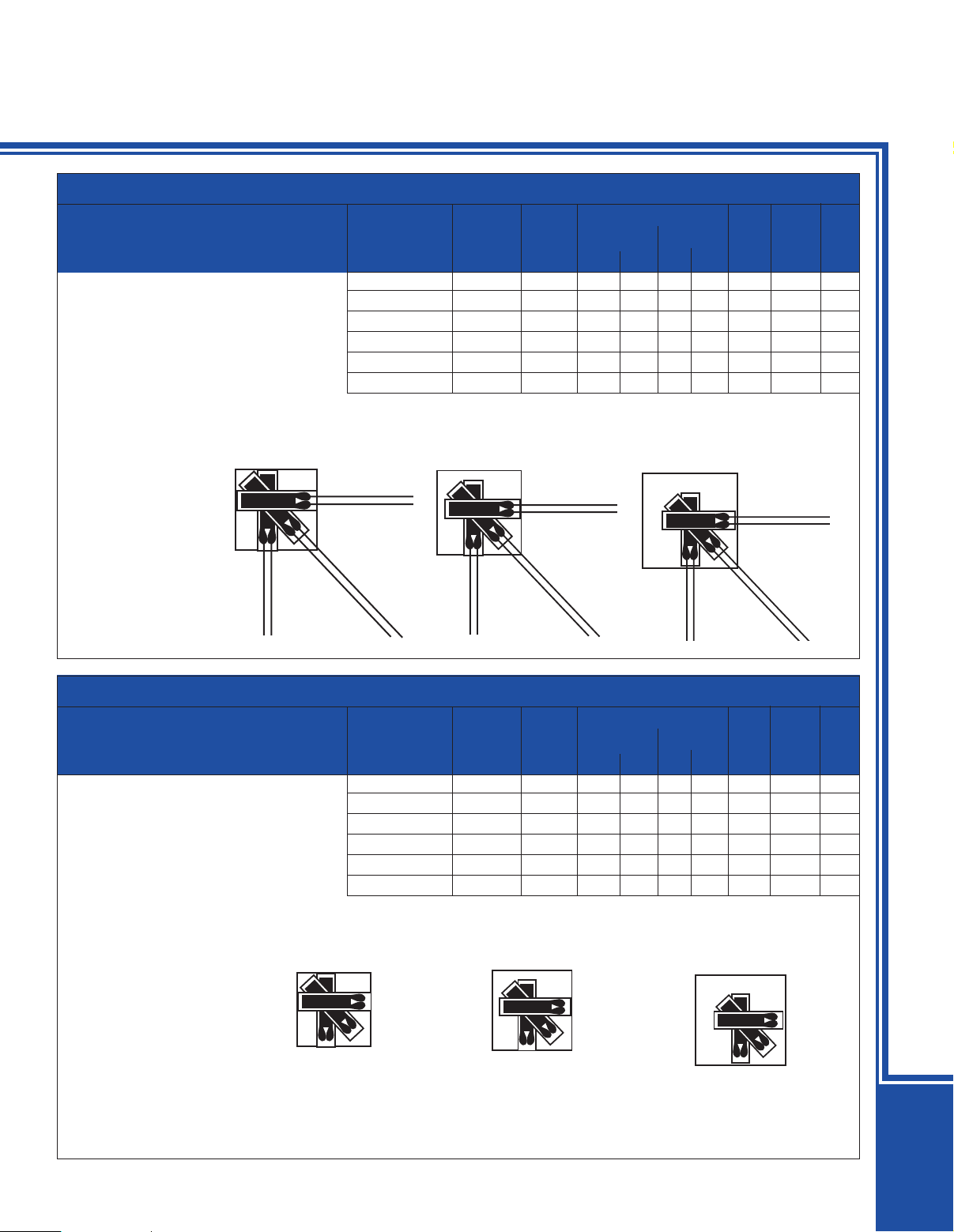
ROSETTE STRAIN GAGES
To Order
TYPE SERIES PRICE GRID CARRIER
U 0°/45°/90° Encapsulated with
Ribbon Leads
RY51
Temperature characteristics
matched to carbon steel
RY53
Temperature characteristics
matched to aluminum
(Specify Model Number)
Diagrams Shown Larger
Than Actual Size
Fig. 1
DIMENSIONS [MM]
PER PKG MAX TERM
MODEL NO. OF 5 OHMS A B C D EXC PADS FIG
SG-2/120-RY51 $125 120 2.0 1.8 6.3 5.0 5 TP-1 1
SG-3/350-RY51 139 350 3.0 1.6 7.0 6.8 8 TP-2 2
SG-7/120-RY51 165 120 6.0 3.0 12.0 11.0 10 TP-3 3
SG-2/120-RY53 125 120 2.0 1.8 6.3 5.0 5 TP-1 1
SG-3/350-RY53 139 350 3.0 1.6 7.0 6.8 8 TP-2 2
SG-7/120-RY53 165 120 6.0 3.0 12.0 11.0 10 TP-3 3
Fig. 2 Fig. 3
For Accessory
Terminal Pads,
see page E-25.
To Order
TYPE SERIES PRICE GRID CARRIER
U 0°/45°/90° Encapsulated with
Solder Tabs
RY61
Temperature characteristics
matched to carbon steel
RY63
Temperature characteristics
matched to aluminum
Ordering Example:
SG-7/120-RY61, package of
five rosette strain gages
encapsulated with solder tabs,
with temperature characteristics
matched to carbon steel and
max. excitation of 9 V, $165.
(Specify Model Number)
DIMENSIONS [MM]
PER PKG MAX TERM
MODEL NO. OF 5 OHMS A B C D EXC PADS FIG
SG-2/120-RY61 $125 120 2.0 1.8 6.3 5.0 5 TP-1 1
SG-3/350-RY61 139 350 3.0 1.6 7.0 6.8 8 TP-2 2
SG-7/120-RY61 165 120 6.0 3.0 12.0 11.0 9 TP-3 3
SG-2/120-RY63 125 120 2.0 1.8 6.3 5.0 5 TP-1 1
SG-3/350-RY63 139 350 3.0 1.6 7.0 6.8 8 TP-2 2
SG-7/120-RY63 165 120 6.0 3.0 12.0 11.0 9 TP-3 3
Diagrams Shown Larger
Than Actual Size
Fig. 1 Fig. 2 Fig. 3
STRAIN GAGES
For Accessory
Terminal Pads,
see page E-25.
E
E-16
Page 2
a
b
c
a
b
c
a
b
c
ab c
a
c
b
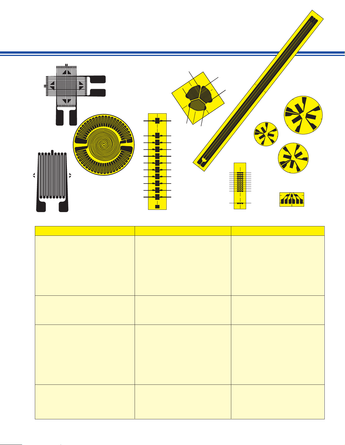
OMEGA®STRAIN GAGES
SPECIFICATIONS CHART
SG SERIES KFG SERIES
Foil strain gages are constructed by
embedding a foil measuring element into
a carrier.
Foil measuring grid Constantan foil 5 µm thick Constantan foil 6 µm thick
Carrier Polyimide Kapton
Substrate thickness 50 µm 15 µm
Cover thickness 25 µm 9 µm
Connection dimensions in (mm) [in] Solder pads or ribbon leads 27 AWG strand polyvinyl insulation
(30 long x.05 thick x 3 wide) (1 x 2) [.04 x .08]
[1.2 long x .002 thick x .012 wide]
Nominal resistance Stated in “to order” box 120 ±0.4 ohms
Resistance tolerance per package 0.5% 03%
Gage factor (µΩ/µ/µΩ) Approximately 2.0 2.10 ±10%
(actual value printed on each package)
Gage factor tolerance per package 1.0% 1.0%
Thermal Properties
Reference temperature 23°C/73°F 23°C/73°F
Service temperature:
Temperature characteristics:
Static measurements -30 to 250°C (-22 to 482°F) -20 to 100°C (-4 to 212°F)
Dynamic measurements -30 to 300°C (-22 to 572°F) -20 to 100°C (-4 to 212°F)
Steel 11 ppm°C (6.1 ppm°F) 10.8 ppm°C (6 ppm°F)
Aluminum 23 ppm°C (12.8 ppm°F) —
Uncompensated ±20 ppm°C (±11.1 ppm°F) —
Temperature compensated range -5 to 120°C (5 to 248°F) 10 to 80°C (50 to 176°F)
Tolerance of temp. compensation 1 ppm°C (0.5 ppm°F) 1 ppm°C (0.5 ppm°F)
Mechanical Properties
Maximum strain 3% or 30,000 µe 5% or 50,000 µe
Hysteresis Negligible Negligible
Fatigue (at ±1500 µe) > 10,000,000 cycles > 10,000,000 cycles
Smallest bending radius 3 mm (1⁄8 inch) 3 mm (1⁄8 inch)
Transverse sensitivity — Stated on each package
E-7
Page 3

One Omega Drive | Stamford, CT 06907 | 1-888-TC-OMEGA (1-888-826-6342) | info@omega.com
EPG05
www.omega.com
UNITED KINGDOM
www. omega.co.uk
Manchester, England
0800-488-488
UNITED STATES
www.omega.com
1-800-TC-OMEGA
Stamford, CT.
CANADA
www.omega.ca
Laval(Quebec)
1-800-TC-OMEGA
GERMANY
www.omega.de
Deckenpfronn, Germany
0800-8266342
Karviná, Czech Republic
FRANCE
www.omega.fr
Guyancourt, France
088-466-342
CZECH REPUBLIC
www.omegaeng.cz
596-311-899
BENELUX
www.omega.nl
Amstelveen, NL
0800-099-33-44
More than 100,000 Products Available!
Temperature
Calibrators, Connectors, General Test and Measurement
Instruments, Glass Bulb Thermometers, Handheld Instruments
for Temperature Measurement, Ice Point References,
Indicating Labels, Crayons, Cements and Lacquers, Infrared
Temperature Measurement Instruments, Recorders Relative
Humidity Measurement Instruments, RTD Probes, Elements
and Assemblies, Temperature & Process Meters, Timers and
Counters, Temperature and Process Controllers and Power
Switching Devices, Thermistor Elements, Probes and
Assemblies,Thermocouples Thermowells and Head and Well
Assemblies, Transmitters, Wire
Flow and Level
Air Velocity Indicators, Doppler Flowmeters, Level
Measurement, Magnetic Flowmeters, Mass Flowmeters,
Pitot Tubes, Pumps, Rotameters, Turbine and Paddle Wheel
Flowmeters, Ultrasonic Flowmeters, Valves, Variable Area
Flowmeters, Vortex Shedding Flowmeters
pH and Conductivity
Conductivity Instrumentation, Dissolved Oxygen
Instrumentation, Environmental Instrumentation, pH
Electrodes and Instruments, Water and Soil Analysis
Instrumentation
Data Acquisition
Auto-Dialers and Alarm Monitoring Systems,
Communication Products and Converters, Data
Acquisition and Analysis Software, Data Loggers
Plug-in Cards, Signal Conditioners, USB, RS232, RS485
and Parallel Port Data Acquisition Systems, Wireless
Transmitters and Receivers
Pressure, Strain and Force
Displacement Transducers, Dynamic Measurement
Force Sensors, Instrumentation for Pressure and Strain
Measurements, Load Cells, Pressure Gauges, Pressure
Reference Section, Pressure Switches, Pressure Transducers,
Proximity Transducers, Regulators,
Strain Gages, Torque Transducers, Valves
Heaters
Band Heaters, Cartridge Heaters, Circulation Heaters,
Comfort Heaters, Controllers, Meters and Switching
Devices, Flexible Heaters, General Test and Measurement
Instruments, Heater Hook-up Wire, Heating Cable
Systems, Immersion Heaters, Process Air and Duct,
Heaters, Radiant Heaters, Strip Heaters, Tubular Heaters
click here to go to the omega.com home page
 Loading...