

Page 1
Page 2

OMEGAnet®On-Line Service Internet e-mail
www.omega.com info@omega.com
omega.com
TM
®
It is the policy of OMEGA to comply with all worldwide safety and EMC/EMI regulations that apply. OMEGA
is constantly pursuing certification of its products to the European New Approach Directives. OMEGA will add
the CE mark to every appropriate device upon certification.
The information contained in this document is believed to be correct, but OMEGA Engineering, Inc. accepts no
liability for any errors it contains, and reserves the right to alter specifications without notice.
WARNING: These products are not designed for use in, and should not be used for, patient-connected
applications.
Benelux:
Postbus 8034, 1180 LA Amstelveen
The Netherlands
TEL: +31 (0)20 6418405 FAX: +31 (0)20 6434643
Toll Free in Benelux: 0800 0993344
e-mail: nl@omega.com
Czech Republic:
Rude´arma´dy 1868, 733 01 Karvina´ 8
TEL: +420 (0)69 6311899 FAX: +420 (0)69 6311114
Toll Free in Czech Republic: 0800-1-66342
e-mail: czech@omega.com
France:
9, rue Denis Papin, 78190 Trappes
TEL: +33 (0)130 621 400 FAX: +33 (0)130 699 120
Toll Free in France: 0800-4-06342 e-mail: france@omega.com
Servicing Europe:
USA and Canada:
Sales Service: 1-800-826-6342 / 1-800-TC-OMEGA
®
Customer Service: 1-800-622-2378 / 1-800-622-BEST
®
Engineering Service: 1-800-872-9436 / 1-800-USA-WHEN® TELEX:
996404 EASYLINK: 62968934 CABLE: OMEGA
USA: ISO 9001 Certified
One Omega Drive, P.O. Box 4047
Stamford CT 06907-0047
TEL: (203) 359-1660
FAX: (203) 359-7700
e-mail: info@omega.com
Servicing North America:
For immediate technical or application assistance:
Mexico:
TEL: (001) 800-826-6342
FAX: (001) 203-359-7807
En Espan~ol: (001) 203-359-7803
e-mail: espanol@omega.com
info@omega.com.mx
Germany/Austria:
Daimlerstrasse 26, D-75392
Deckenpfronn, Germany
TEL: +49 (0)7056 3017 FAX:+49 (0)7056 8540
Toll Free in Germany: 0800 TC-OMEGA
SM
e-mail: germany@omega.com
United Kingdom: ISO 9002 Certified
One Omega Drive
River Bend Technology Centre
Northbank, Irlam
Manchester M44 5EX United Kingdom
TEL: +44 (0)161 777 6611 FAX:+44 (0)161 777
6622
Toll Free in United Kingdom: 0800488488
e-mail: sales@omega.co.uk
Canada:
976 Bergar
Laval (Quebec) H7L 5A1
TEL: (514) 856-6928
FAX: (514) 856-6886
e-mail: info@omega.ca
Page 3

SCR POWER CONTROLLERS
TABLE OF CONTENTS
General Description
and Specifications .................1
Firing Modes .......................2
Installation and Wiring ...............4
Operation .........................9
Troubleshooting....................15
Parts Lists and
Ordering Codes ..................18
Page 4

1
OPERATING INSTRUCTIONS
Series 19 and 39 SCR Power Controllers
Series 91 and 93 SCR Power Controllers
Section 1. General Description
Introduction
SCR Power Controllers are designed to regulate ac power to electrical
heating processes, such as ovens, furnaces, heat sealers, etc. (Note:
They are not designed to drive transformers, coils or other inductivetype loads.)
The controller accepts an input signal, such as 4-20 mAdc from some
signal conditioning device, e.g., a temperature controller. For most
processes, the combination of a temperature controller and SCR
power controller will provide very accurate, automatic temperature
control. For manual operation, a manual control option with a remote
potentiometer is available.
General Specifications
Inputs: 4-20 mAdc standard, or as ordered (see
serial number) minimum voltage
requirements 10 Vdc; all inputs
electrically isolated via optical coupling
Supply Voltage: 110/120; 208/240; 440/480, 575/600
Vac, or as ordered (Phase connection
not critical on 3-phase units)
Frequency: 50/60 Hz
Ambient Temperature: 30
o
to 122oF for listed power ratings
Cooling: Convection
Protection: Sub-cycle, current-limiting fuse; transient
voltage suppresion
Load Resistive, 1- or 3-phase - 3-wire Wye or Delta
All specifications subject to change.
Page 5
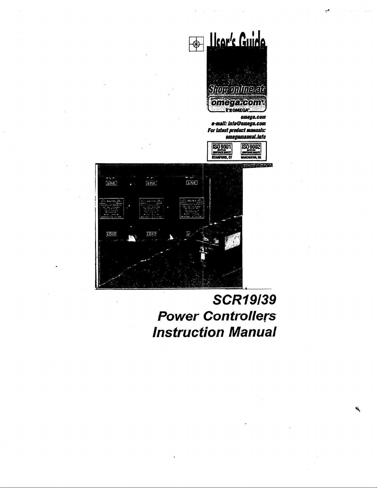
2
0.2 Second
Time Base
On
Off
Figure 1. Time-proportioned, zero-cross burst.
Section 1. Firing Modes
Zero-Crossing Control
A zero-crossing switched (zer-switched or burst fired) SCR
power controller works by triggering at the moment when the
value of the ac sine wave is at the baseline or “zero” voltage
point (Figure 1.) This results in a “burst” of full line voltage with
no RFI. SCR power controllers utilize a patented trigger
circuit that turns on the SCRs as close as possible to the ac
zero voltage point. Proportioning action is obtained by varying
the number of cycles on to the number of cycles off. The
output will vary from a few cycles on and a large number of
cycles off at low input, through halh the cycles on and half off
at half input, to all cycles on at maximum input. This output
is integrated by the heaters which produce a smoothly
proportioning heat output that varies directly with the input
signal.
Page 6
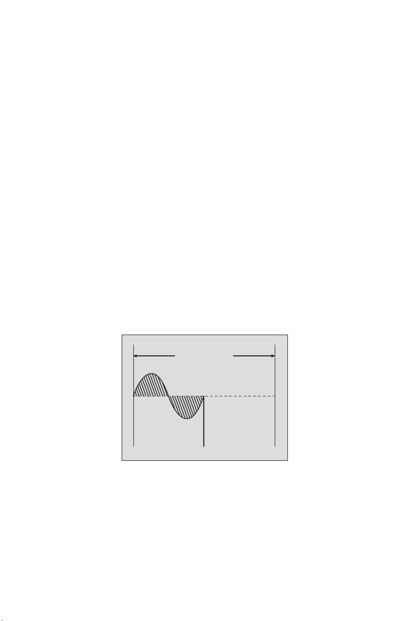
Phase-Angle Control
A phase-angle type SCR power controller works by delaying
the trigger pulse to some point in the half cycle of the ac
wave. This trigger point, from 0 to 180 degrees, is referred to
as the phase angle (Figure 2). The SCR will turn on when
triggerred, and remain on for the rest of the half cycle.
Increasing the control signal will cause the trigger pulse to
occur earlier in the half cycle, thus delivering a greater portion
of the wave to the load.
Because it provides an extremely fast response, phase-angle
control should be used in low-mass element applications that
require high switching speeds, such as tungsten elements,
quartz lamps, hot wires and other loads subject to high inrush
currents. (Note: Some RFI can be generated from the phaseangle controller) SCR phase-angle power controllers are available with a soft-start timing option that provides a ramp to
peak voltage, and are available with a voltage limit option that
“clamps” output voltage to a level lower than the supply
voltage.
3
Figure 2. Phase-angle changes and their effect on output power.
Phase angle = 113°, 293°
Power = 25%
0° 360°
180 °
11 3 °
293°
Page 7

4
Section 3. Installation
3.1 Mounting
Mount the controller, with the heat sinks in a vertical position,
in a reasonably cool location -- 50
o
C (122oF) maximum.
Some space should be left above and below the unit to allow
for air circulation. If the controller must be placed in an
environment where the ambient temperature exceeds 50oC
(122
o
F), it will be necessary to derate the unit. If derating is
not possible, venting or an exhaust fan must be used to keep
ambient temperatures at an acceptable level. (See Figure 3
for cooling calculations).
Formula for minimum metal enclosure size
for convection cooling
.72 x AMPS x # of Controlled Legs Min. Exposed
=
122
o
F - Ambient oF Sq. Ft.
.40 x AMPS x # of Controlled Legs Min. Exposed
=
50oC - Ambient oC Sq. Ft.
Formula for forced air cooling
2.2 x AMPS x # of Controlled Legs
= Min. CFM
50
o
C - Ambient oC
3.8 x AMPS x # of Controlled Legs
= Min. CFM
122oF - Ambient oF
Figure 3. Calculations for determining cooling requirements
Page 8
3.2 Wiring
The wiring components of SCR power controllers consists of
line voltage, heater, load, and signal input. Follow the wiring
diagrams on the following pages (Figures 4 and 5) and the
terminal labels on the unit. On three-phase controllers (Series
39), it is not necessary to connect the phases to any
particular terminal. Because the controllers are
phase-to-phase controllers, either Wye or Delta connected
loads may be used.
Wire gauge for power and load connections will vary depending on the size of the load. Standard electrical code
procedures should be followed. Do not exceed the voltage
and ampere ratings indicated on the controller’s label. Before
connecting the controller to a heater, we recommend that the
heater be connected directly to the power line to ensure that
the current rating is correct and that no shorts exist.
5
CAUTION
On Wye connected loads, do not connect the
center terminal to the line or to the ground.
Page 9
6
CAUTION:
Possible Shock Hazard -- Exposed high voltage exists on heat
sinks and other parts of these units.
To prevent possible electrocution, the
controller must be locked in a secure
enclosure during operation. Solid
state devices do not completely
remove power from the load, even in
the OFF state. This leakage current
presents a potential shock hazard at
all unit and load terminals. All power
must be completely off before servicing
.
Only qualified personnel should be
allowed access.
Possible Fire Hazard -- Because SCR power controls and
associated equipment are not fail-safe
devices, an approved temperature
and/or pressure safety control should
be used to ensure safe operation.
Page 10

7
Figure 4a. Wiring scheme for Series 19Z.
Figure 4b. Wiring scheme for Series 39Z.
3.21 Zero-Cross
Zero-cross mode power controllers may only be used with
constant resistance heating elements, such as Nichrome. They
are NOT intended for high-inrush loads. Depending on the type
of element used, you can oversize the load controller.
Figure 5a. Wiring scheme for Series 19P.
Figure 5b. Wiring scheme for Series 39P.
Page 11

8
3.23 Fuses and Safety Warnings
Only I2fuses should be used for protecting the power
controller’s SCRs. These fuses are especially designed to
protect the solid state devices under short-circuit conditions;
other fuses may not act quickly enough. If it becomes
necessary to replace a fuse, use only a Chase-Shawmut
Form 101 or semiconductor fuse, or equivalent.
IMPORTANT SAFETY WARNINGS - READ BEFORE
OPERATING CONTROLLER.
Standard fuses or a circuit breaker should be used on
all power lines for safety and to meet electrical code
requirements. The supplied fuses are for protecting the
SCRs only and are not acceptable as power line fuses.
SCR power controllers do not satisfy electrical code
disconnect requirements in the non-conducting or OFF
state. Because they are semiconductor devices, the
have a leakage current in the OFF state on the order of
10mA at rated line voltage. Therefore, the controller
should be connected to a circuit breaker or disconnect
switch.
SCRs can fail in a “shorted-closed” mode, resulting in
full application of power. Use of a seperate, thermally
protected safety contactor is strongly recommended.
Page 12

Section 4. Operation
4.1 Series 19Z/39Z
The Series 19Z and 39Z power controllers are designed to
control ac power to electrical heating processes, such as
ovens, furnaces, heat sealers, etc. (Note: They are NOT
intended to drive transformer coupled or inductive loads.)
The controllers consist of power semiconductors (SCRs),
properly sized heat sinks, and trigger circuitry. These
controllers accept a control signal (e.g., 4-20 mAdc) from a
signal conditioning device, such as a temperature controller.
The “Z” suffix designates the controller as operating in the
Zero Cross, Zero Voltage Switched, or Zero Burst firing mode.
A patented trigger circuit turns on the SCRs as close as
possible to the point at which the ac sine wave crosses
through zero. In effect, this turns the line voltage on and off
in full cycles. With an input of 4-20 mA , the output will be
FULL OFF below 4 mA and FULL ON at 20 mA.
Proportioning action is obtained by varying the number of
cycles ON to the number of cycles OFF. The resulting output
power is integrated by the heaters to produce smoothly
proportional heating that varies directly with the input signal.
9
Series
19/39
Page 13

4.2 Series 19P/39P
The Series 19P and 39P power controllers are designed to
control ac power to electrical heating processes, such as
ovens, furnaces, heat sealers, etc. (Note: They are NOT
designed to drive transformer-coupled loads.) The controllers
consist of power semiconductors (SCRs), properly sized heat
sinks, and trigger circuitry.
These controllers accept a control signal (e.g., 4-20 mAdc)
from a signal conditioning device, such as a temperature
controller.
The “P” Suffix designates the controller as operating in the
Phase-Angle firing mode. Providing full proportional control,
SCRs are turned ON during each 1/2 cycle at apoint (phase
angle) of the ac sine wave, remaining ON for the rest of the
1/2 cycle. By varying the phase angle setting, the amount of
voltage reaching the load may be adjusted. The output
voltage is proportional to the input signal. At 4 mA input, no
voltage will be applied to the load; at 20 mA input, the
output voltage will almost equal the line voltage.
10
Page 14

11
4.3 Voltage Limit Option (Phase-Angle Fired Units Only)
The output voltage of the controller can be limited by
adjusting the trimmer on the printed circuit board. Turning
the adjustment clockwise will increase the out put voltage
limit. This control will operate over a range of about 20% to
full output. Ordinarily, this adjustment is used to protect
heaters that cannot operate on full line voltage, or to limit the
maximum heating of a process.
4.4 Soft Start Option (Phase-Angle Fired Units Only)
The soft start circuitry is used to slowly turn on the voltage
from the controller to the load. It is used to protect the
controller when it is operating into loads having high-current,
turn-on characteristics, e.g., quartz or tungsten heaters. The
output voltage will rise from zero to full output over various
times, depending on the time option selected.
The soft start circuit presents an initial high impedance which
is inserted between the signal source and the controller. This
impedance decreases in value with time. Soft start action
can be seen as the input signal slowly changes from 4-20 mA
when full output is required.
Page 15

4.5 Manual Option
A module board is added to the standard controller which
converts a variable resistance potentiometer to a 0-20 mA
signal. This signal is then applied to the input of the standard
trigger board and operates the controller in the standard
manner (Figure 6). The input potentiometer can be any
three-lead pot from 100 to 1000 ohms. The pot supplied
with the manual option is 500 ohms. This pot has a 0-10
scale and knob. There will be no output at the “0” setting
and full output at the “10” setting.
12
Figure 6. Wiring diagram for manual control (Option module M required).
120/240/480/600Vac
RED
0 -20 dc
BLACK
+
–
TRIGGER
BOARD
(1000 Ω MAX)
Page 16

4.6 Thermostat Option
The module will also operate from a standard 135-ohm
thermostat. Connect the three output wires to the controller
as shown on the drawing (Figure 7) and on the terminal strip.
If the output terminals on the thermostat are not marked in
the same fashion, connect the center wire to the CT point on
the terminal strip, connect the other two wires to the CW
and CCW points. The controller should then provide an
output as the thermostat setpoint is increased. If the reverse
action occurs, interchange the CW and the CCW wires.
13
Figure 7. Wiring diagram for thermostatic control (Option H required).
120/240/480/600 Vac
Hot
Cold
0 -20 dc
+
–
TRIGGER
BOARD
(1000 Ω MAX)
Page 17

4.7 Maintenance
SCR power controllers require little, if any, maintenance.
However, as with all products exposed to industrial
environments, they should be cleaned periodically to prevent
corrosion and to remove any surface dust, dirt, and oil. We
also recommend inspecting, and re-tightening if necessary, all
electrical and mechanical connections (lugs, terminals, fuses,
buss bars, etc.)
14
WARNING: Before Touching Controller Parts,
Make Sure Power Is Disconnected.
Page 18

15
4.8 Troubleshooting
If the power controller is not functioning properly, refer to
these troubleshooting procedures.
Symptom: No heat or reduced heat output.
Possible Cause(s) Action
1. Loss of line voltage. Check power
supply.
2. Line fuse or controller fuse blown. Check heater for
short circuit and
correct problem.
3. No input signal. Check signal
conditioner.
4. Malfunction on trigger board. Consult factory.
5. Open SCR Consult factory.
Page 19

16
Trigger board
malfunction
Shorted SCR
Signal source
defective
Reconnect properly
Line and
load connections
reversed
Disconnect
input
signal wires
Output off?
Turn power
back on
Turn off power
and disconnect
gate wires
Heater
amps
present?
Yes
No
No
No
Yes
Yes
Troubleshooting Flowchart
Symptom: Heaters will not turn off.
Page 20

Input Signal Problems: In normal operation, the green LED will
illuminate if an input signal of proper polarity is present. Its
brightness indicates signal level.
Symptom: Red or amber input LED is lit
Red: Polarity of input signal is reversed (Change polarity).
Amber: AC on input signal (Check signal source).
Output Signal Problems: In normal operation, the amber LED
will illuminate if an output voltage is present. Its brightness
indicates output level.
Symptom: Output LED lit with no input.
Symptom: Output LED is red or green with input.
Check and correct the following conditions:
1. Gate wire unplugged or broken
2. Open SCR
3. Trigger board malfunction
4. Balance pot misadjusted (Phase-angle controllers only)
17
Trigger board malfunction
Heater circuit open
Shorted SCR
Reconnect properly
Line and load
connections reversed?
Turn off power
and disconnect
gate wires
Heater
amps
present?
Yes
No
Heater
amps
present?
Yes
No
No
Yes
Page 21

18
Section 5. Parts Lists
Series 19/39
MODEL # FUSES SCR MODULE SCR MODULE
(Voltage / Load) (19P, 19Z, 39Z) (39P)
24040/12040 A050F040 IRKT 57-10 IRKH 72-10
24060/12060 A050F060 IRKT 57-10 IRKH 72-10
24080/12080 A050URG080XAA IRKT 92-10 IRKH 92-10
48040 A050F040 IRKT 57-10 IRKH 72-10
48060 A070F060 IRKT 57-10 IRKH 72-10
48080 A070URGC080WA IRKT 92-10 IRKH 92-10
Page 22

19
Athena Model No:
9
SWITCHING MODE
Code
*P Phase angle firing
Z Zero switched
Ordering Example:
Model 39Z-24-040-P-0-00
Three phase, zero switched,
208/240 Vac line voltage, 40 amps,
pulsed dc input, no options, no timing.
(Use “0” for all spaces not used.)
ACCESSORIES
Manual Station with Remote Potentiometer
(Requires Input “A” on SCR unit)
90M001-120 (120 Vac supply voltage)
90M001-240 (240 Vac supply voltage)
90M001-480 (480 Vac supply voltage)
90M001-600 (600 Vac supply voltage)
SOFT START / VOLTAGE
LIMIT P SERIES ONLY
Code (Soft Start Timing
0 None
A9 Seconds
B 15 Seconds (Standard)
C 30 Seconds
D 60 Seconds
INPUTS
Code
A 4-20 mA
C 10-50 mA
D Other mA or Voltage (Specify)
P Pulsed dc (Z series only)
PHASE
Code
1 Single
3 Three
AC LINE VOLTAGE (50/60 HZ)
24 = 02 440/480 = 48
110/120 = 12 575/600 = 60
208/240 = 24
LOAD CURRENT
(AMPS)
Code
040 40 Amps
060 60 Amps
080 80 Amps
OPTIONS
Consult Factory
00 None
0A Fuses
*Specify voltage code
Section 6. Model Identification
Ordering Codes: Series 19/39
Page 23

Section 7. Dimensions
Series 19/39
Warranty
This equipment is warranteed to be free from defects of
material and workmanship. It is sold subject to our mutual
agreement that the liability of the manufacturer is limited to
replacement and/or repair at its factory, provided the
equipment is returned, transportation prepaid, within one (1)
year of purchase.
The purchaser agrees that the manufacturer shall assume no
liability for consequential damages resulting from its use or
from packaging of shipments returned to the factory.
Components that wear or are damaged by misuse are not
warranted. These include contact points, fuses and triacs.
Units that have been customer modified are not warranted.
Specifications are subject to change without notice.
20
19Z 19P 39Z 39P
Dimensions Dimensions Dimensions Dimensions
H x W x D H x W x D H x W x D H x W x D
(in) (in) (in) (in)
7 x 4.75 x 4 7 x 4.75 x 4 7 x 9.62 x 4 7 x 14.37 x 4
Notes: If fuses are added to unit, add 3 1/4". Overall depth is 4".
Page 24

21
NOTES
Page 25

22
NOTES
Page 26

23
NOTES
Page 27

24
OMEGA’s policy is to make running changes, not model changes, whenever an improvement is possible.
This affords our customers the latest in technology and engineering.
OMEGA is a registered trademark of OMEGA ENGINEERING, INC.
© Copyright 2004 OMEGA ENGINEERING, INC. All rights reserved. This document may not be copied, photocopied, reproduced, trans-
lated, or reduced to any electronic medium or machine-readable form, in whole or in part, without the prior written consent of OMEGA
ENGINEERING, INC.
WARRANTY/DISCLAIMER
OMEGA ENGINEERING, INC. warrants this unit to be free of defects in materials and workmanship for
a period of 13 months from date of purchase. OMEGA’s Warranty adds an additional one (1) month
grace period to the normal one (1) year product warranty to cover handling and shipping time. This
ensures that OMEGA’s customers receive maximum coverage on each product.
If the unit malfunctions, it must be returned to the factory for evaluation. OMEGA’s Customer Service
Department will issue an Authorized Return (AR) number immediately upon phone or written request.
Upon examination by OMEGA, if the unit is found to be defective, it will be repaired or replaced at no
charge. OMEGA’s WARRANTY does not apply to defects resulting from any action of the purchaser,
including but not limited to mishandling, improper interfacing, operation outside of design limits,
improper repair, or unauthorized modification. This WARRANTY is VOID if the unit shows evidence of
having been tampered with or shows evidence of having been damaged as a result of excessive corrosion; or current, heat, moisture or vibration; improper specification; misapplication; misuse or other
operating conditions outside of OMEGA’s control. Components which wear are not warranted, including but not limited to contact points, fuses, and triacs.
OMEGA is pleased to offer suggestions on the use of its various products. However,
OMEGA neither assumes responsibility for any omissions or errors nor assumes liability for any damages that result from the use of its products in accordance with information provided by OMEGA,
either verbal or written. OMEGA warrants only that the parts
manufactured by it will be as specified and free of defects. OMEGA MAKES NO OTHER
WARRANTIES OR REPRESENTATIONS OF ANY KIND WHATSOEVER, EXPRESS OR IMPLIED, EXCEPT
THAT OF TITLE, AND ALL IMPLIED WARRANTIES INCLUDING ANY WARRANTY OF MERCHANTABILITY AND FITNESS FOR A PARTICULAR PURPOSE ARE HEREBY DISCLAIMED. LIMITATION OF LIABILITY: The remedies of purchaser set forth herein are exclusive, and the total liability of OMEGA with
respect to this order, whether based on contract, warranty, negligence, indemnification, strict liability
or otherwise, shall not exceed the purchase price of the component upon which liability is based. In
no event shall OMEGA be liable for consequential, incidental or special damages.
CONDITIONS: Equipment sold by OMEGA is not intended to be used, nor shall it be used: (1) as a
“Basic Component” under 10 CFR 21 (NRC), used in or with any nuclear installation or activity; or (2)
in medical applications or used on humans. Should any Product(s) be used in or with any nuclear
installation or activity, medical application, used on humans, or misused in any way, OMEGA assumes
no responsibility as set forth in our basic WARRANTY / DISCLAIMER language, and, additionally, purchaser will indemnify OMEGA and hold OMEGA harmless from any liability or damage whatsoever
arising out of the use of the Product(s) in such a manner.
RETURN REQUESTS/INQUIRIES
Direct all warranty and repair requests/inquiries to the OMEGA Customer Service Department. BEFORE
RETURNING ANY PRODUCT(S) TO OMEGA,PURCHASER MUST OBTAIN AN AUTHORIZED RETURN (AR) NUMBER
FROM OMEGA’S CUSTOMER SERVICE DEPARTMENT (IN ORDER TO AVOID PROCESSING DELAYS). The
assigned AR number should then be marked on the outside of the return package and on any
correspondence.
The purchaser is responsible for shipping charges, freight, insurance and proper packaging to prevent
breakage in transit.
FOR W
ARRANTY RETURNS, please have the following information available BEFORE
contacting OMEGA:
1. Purchase Order number under which
the product was PURCHASED,
2. Model and serial number of the product under
warranty, and
3. Repair instructions and/or specific
problems relative to the product.
FOR NON-WARRANTY REPAIRS,
consult OMEGA for
current repair charges. Have the following information available BEFORE
contacting OMEGA:
1. Purchase Order number to cover the
COST of the repair,
2. Model and serial number of the
product, and
3. Repair instructions and/or specific problems
relative to the product.
Page 28

M4100/1004
Where Do I Find Everything I Need for
Process Measurement and Control?
OMEGA…Of Course!
Shop online at www.omega.com
TEMPERATURE
✓
Thermocouple, RTD & Thermistor Probes, Connectors,
Panels & Assemblies
✓
Wire:Thermocouple, RTD & Thermistor
✓
Calibrators & Ice Point References
✓
Recorders, Controllers & Process Monitors
✓
Infrared Pyrometers
PRESSURE, STRAIN AND FORCE
✓
Transducers & Strain Gages
✓
Load Cells & Pressure Gages
✓
Displacement T r ansducers
✓
Instrumentation & Accessories
FLOW/LEVEL
✓
Rotameters, Gas Mass Flowmeters & Flow Computers
✓
Air Velocity Indicators
✓
Turbine/Paddlewheel Systems
✓
Totalizers & Batch Controllers
pH/CONDUCTIVITY
✓
pH Electrodes, Testers & Accessories
✓
Benchtop/Laboratory Meters
✓
Controllers, Calibrators, Simulators & Pumps
✓
Industrial pH & Conductivity Equipment
DATA ACQUISITION
✓
Data Acquisition & Engineering Software
✓
Communications-Based Acquisition Systems
✓
Plug-in Cards for Apple, IBM & Compatibles
✓
Datalogging Systems
✓
Recorders, Printers & Plotters
HEATERS
✓
Heating Cable
✓
Cartridge & Strip Heaters
✓
Immersion & Band Heaters
✓
Flexible Heaters
✓
Laboratory Heaters
ENVIRONMENTAL
MONITORING AND CONTROL
✓
Metering & Control Instrumentation
✓
Refractometers
✓
Pumps & Tubing
✓
Air, Soil & Water Monitors
✓
Industrial Water & Wastewater Treatment
✓
pH, Conductivity & Dissolved Oxygen Instruments
 Loading...