

Page 1
SELECTION GUIDE FOR OMEGA®ZENER
FM
APPROVED
BARRIERS FOR INTRINSIC SAFETY
OMEGA®Solid State
Relays and Zener
Barriers for
Intrinsic Safety
The maximum energy
possible at the switch
terminals of the OMEGA
zener barriers is far below the
explosive point of the most
volatile surrounding gas
conditions. The type of
non-voltage-producing
switch or sensor best
fitted for the application
can be used, since
the entire switching
circuit is rendered
intrinsically safe by the
OMEGA®zener barrier.
Because the switching
circuit is low voltage, there
is no shock hazard to
operating or maintenance
personnel.
Installation
and Maintenance
OMEGA®zener barrier
units are normally
installed in a safe area
and connected to the
sensor in a hazardous location;
no explosion-proof or protective
housings are needed. Units install
singly in any position, or can be
grouped on a common earthgrounded plate with mounting tabs
to provide electrical grounding.
Between 6 and 32 threaded
electrical terminals are conveniently
placed atop the unit housings.
®
Single- and dualchannel zenner
barriers, shown
smaller than
actual size.
OMEGA®zener barriers must be installed in conformance with the National Electrical
Code and the Instruction, Installation and Service Bulletin supplied with all units.
Periodic checks of ground bonding and cleanliness of units and terminals constitute
the only maintenance required.
Approvals Hazardous Locations
Group
Model No. UL FM CSA Class Division ABCD EFG
SBG111950 XXX I,II 1,2 XXXX XXX
Single
Channel SBG111956 XXX I,II 1,2 XXXX XXX
Zener Barriers
Dual Channel
Zener Barriers
Note: Zener barrier model numbers SBG54803 and SBG54806 are certified by CSA for mounting inside a suitable enclosure in Div. 2 or
non-hazardous locations and must be connected by means of the 2 studs provided to a grounded copper busbar or equivalent.
SBG111954 XXX I,II 1,2 XXXX XXX
SBG113000 XXX I,II 1,2 XXXXX
SBG114166 XXX I,II 1,2 XXXX XXX
SBG54803 XXX I,II 1,2 XXXX
SBG54806 XXX I,II 1,2 X
K-105
Page 2
POWER
SUPPLY
ANNUNC.
POWER
SUPPLY
ANNUNC.
(+)
(–)
(+)
(–)
FUSE
FUSE
1
2
1
3
4
2
7
5
6
8
HAZARDOUS AREA SAFE AREA
HAZARDOUS AREA SAFE AREA
SENSOR
SIGNAL
CONDITIONER
ZENER BARRIER
EARTH GROUND
(2 PLACES)
ZENER
BARRIER UNITS
EARTH GROUNDED
MOUNTING PLATE
INTRINSICALLY
SAFE WIRING
RESISTANCE TO GND.
MUST BE LESS THAN
1 FROM
MOUNTING SCREW
OR BRACKET TO
EARTHING MEMBER
TO ENSURE INTEGRITY
NON-INTRINSICALLY
SAFE WIRING
INTRODUCTION TO SOLID STATE SINGLE-
FM
APPROVED
AND DUAL-CHANNEL ZENER BARRIERS
FOR INTRINSIC SAFETY
OMEGA®SingleChannel and DualChannel Zener
Barriers Feature
Intrinsic Safety
With Solid State
Reliability—And
These Additional
Advantages:
⻬ Installation
Economy
⻬ No Explosion-
Proof Enclosures of
any Kind Needed for
Sensor Wiring
⻬ Compact Size—
Streamlines Multiple
Installations
⻬ Encapsulated
Construction—
Impervious to Dust and
Moisture, Shock and
Vibration Resistant
Single- and DualChannel Barriers
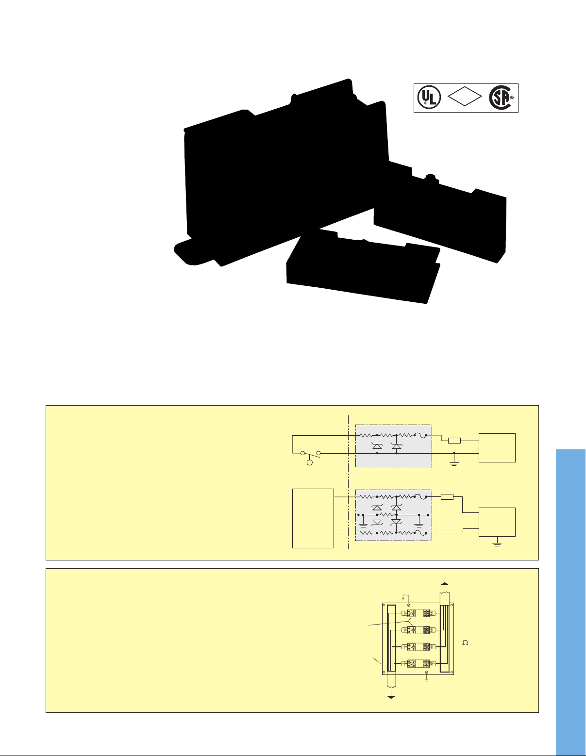
For most non-voltage-producing
devices located in a hazardous
area, a single zener barrier that is
negative-earth-grounded (see figure
1) can be used for intrinsic safety.
Instrumentation that produces an
output (signal conditioners) usually
SBG54803 dual-channel zener
barrier, $315, shown smaller
than actual size.
SBG111950 single-channel
zener barrier, $132, shown
smaller than actual size.
requires two barriers,
one for each “floating”
lead. Here, a dual-channel barrier can
be provided (see figure 2), or for
applications in which the instrument
signal return level cannot be
reduced, a supply barrier and a low
resistance return barrier can be
supplied (see diagram 2B on
page K-110).
Sensor switch may be any non-voltage-producing
device. Flow and level switches, temperature
switches (thermostats), pressure switches, or
passive, resistive transducers or transmitters are
typical.
Fig. 1 Positive single-channel zener barrier with
Fig. 2 Positive dual-channel zener barrier with
Note: Terminals 3, 4, 5, and 6 are common and
Installation and Maintenance
OMEGA®Zener barriers are installed in non-hazardous
(safe) locations, and may be grouped on a common,
earth-grounded mounting plate. Intrinsically safe sensor
wiring must be separated from non-intrinsically-safe input
wiring in separate conduits or raceways to prevent by-pass
during testing or servicing. Routine inspections every two
years or less to check integrity of earth-grounding and
electrical connections, and to make sure the unit is clean,
constitute the only maintenance normally required.
Installation and maintenance must be in accordance with the
National Electrical Code and the applicable OMEGA
operator’s manual.Ω
negative ground.
floating leads.
are bonded to the mounting tabs for positive
redundant grounding.
Figure 1
K
Figure 2
®
K-106
Page 3
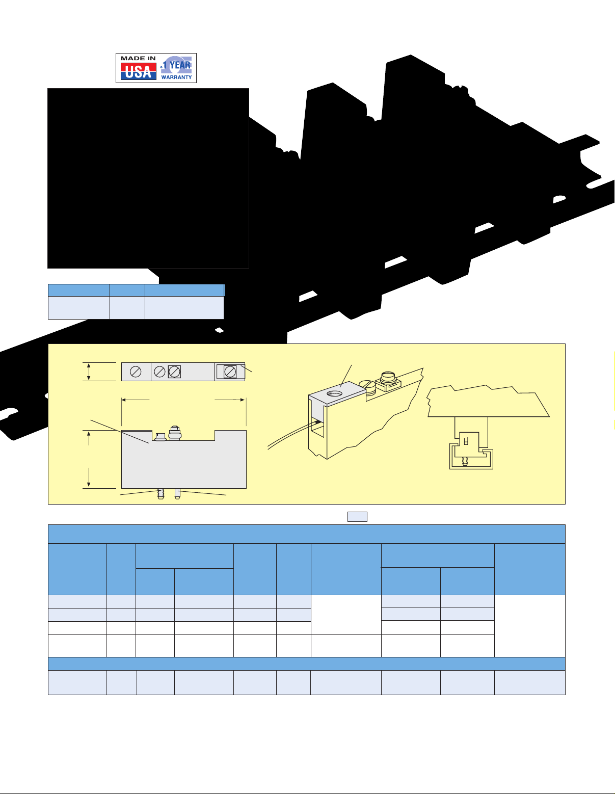
SINGLE-CHANNEL ZENER BARRIERS, DC
81 (3-3/16)
36.5
(1-7/16)
12.3
(31/64)
2
3
1
Mounting Accessories
Model No. Price Description
SBG113530 $20 TS32 style rail
mounting clip
SBG111950 single-channel
zener barrier, $132, shown
smaller than actual size.
Output
terminal cover
Mounting screw
Red polysulfone
housing
Locating Pin
Protective cover over the
output terminal (3).
SBG113530 optional rail
mounting clip, $20.
Single-channel zener barriers can
be supplied with a clip for rail
mounting. Clip attaches to barrier
with mounting screw supplied.
Dimensions: mm (in)
MOST POPULAR MODELS HIGHLIGHTED!
To Order (Specify Model Number)
DC Input to
Barrier, Max
Model No. Price Voltage Current, mA Polarity Ω Div. 1, 2 µF mH Temperature
SBG111950 $132 +15 250 Positive 183 0.32 2.0
SBG111954 132 +24 62 Positive 390
SBG111956 132 +30 62 Positive 750
SBG11300 132 +30 250 Positive 303
SBG114166 132 +30 250 Positive 33.9
The exceptionally compact, almost "wafer-thin" design single-channel zener barriers save space and simplify installation, especially in multiples
on a common mounting plate. Single-screw mounting is standard; units can be supplied with an optional clip for rail mounting. The single
through-mounting screw also provides an electrical connection to ground through the earth-grounded mounting surface.
Ordering Example: SBG111954, zener barrier, 24 V, 62 mA and SBG113530, rail mounting clip, $132 + 20 = $152.
Note: Order rail mounting clip separately.
Fuse Rating Signal Resist. Class I & II, Capacitance Inductance Operating
Series
Signal Return Barrier
Applications
Groups
Groups A, B, C,
D, E, F, G
Groups C, D,
E, F, G
Groups A, B, C, -40 to 60°C
D, E, F, G
Reactive Limits
0.12 3.0 -40 to 60°C
0.07 1.8 (-40 to 140°F)
0.20 3.0
0.07 0.35
(-40 to 140°F)
K-107
Ambient
Page 4

DUAL-CHANNEL ZENER BARRIERS, DC
8 7 6
5
4 7 2
1
152.4 (6)
139.7 (5-1/2)
OUTPU T TERMINALS
NO. 6-32 TH D
MOUNTING TA B
5.6 (7/22) DIA.
3 MTG HOLES
INPU T TERMINALS
NO.6-32 THD.
120.6 (4-3/4)
69.8 (2-3/4)
HOUSIN G R AIL MOUNTING
OPTIONA L
41.3
(1-5/8)
OUTPU T
TERMINA L
COVER
SBG61783, $20,
shown smaller
than actual size.
Mounting Accessories
Model No. Price Description
SBG61783 $20 Rail mounting clips
for dual-channel
zener barriers
SBG54803, $315,
shown smaller
than actual size.
Typical applications for dual-channel zener barriers include solenoids, switches or 4 to 20 mA DC transmitters. When applicable, using a
dual-channel barrier can save money in installation over 2 single-channel barriers.
Ordering Example: SBG54803, 20 V, 100 mA zener barrier, and SBG61783, mounting clips, $315 + 20 = $335.
Note: Order rail mounting clips SBG61783 separately.
Dimensions: mm (in)
Dual-channel zener
barriers can be
mounted with a clip
for rail mounting.
Standard tabs on
barrier allow
surface mounting.
A protective cover
ensures intrinsic
safety integrity of
sensor terminals
and wiring.
To Order (Specify Model Number)
DC Input to
Barrier, Max
Fuse Rating Signal Resist. Class I & II, Capacitance Inductance Operating
Note 1: Dual-channel zener barriers are internally fused.
Note 2: Housing material is blue Lexan
Note 3: For typical wiring diagrams,
Applications
Series Groups
If a "fault" or abnormal signal level continues for
a sustained period, the internal fusing within the
barrier will open, disconnecting the barrier.
External fuses (Littlefuse Type 3AG or equal) are
recommended to protect the barrier from
incorrect wiring at start-up, or from other
equipment fault.
see pages K-109 and K-110.
®
.
MOST POPULAR MODEL HIGHLIGHTED!
Reactive Limits
Ambient
Model No. Price Voltage Current, mA Polarity Ω Div. 1, 2 µF mH Temp.
SBG54803 $315 20 100 Positive 270 Groups A, B, C, D -3.2 -10 -40 to 60°C
SBG54806 315 30 60 Positive 270 Group D 2.4 6.0 (-40 to 140°F)
K-108
K
Page 5

32 1
NON-HAZARDOUS
AREA
HAZARDOUS
AREA
OPTO
COUPLER
32 1
+5 VDC
SUPPLY
RETURN
RETURN
OPTO
COUPLER
MICROPROCESSOR
ZENER
BARRIERS
32 1
876
5
432
1
TERM. EQUIP.
(BY CUST.)
V+
COM.
R
L
AC
INPUT
SOURCE**
ZENER BARRIER
** INPUT POWER FROM
SOURCE NOT GREATER
THAN 250 VAC
STUD COVER MUST BE IN PLACE
WHEN BARRIER IS IN USE.
SENSOR
SWITCH
HAZARDOUS
LOCATION
NON-H AZARDOU S AREA
32 1
NON-HAZARDOUS
AREA
HAZARDOUS
AREA
SENSOR,
SINGLE
STATION
SWITCH
DC POWER
SUPPLY
ANNUNC.
(–)
(+)
FUSE*
SUPPLY
BARRIER
32 1
NON-HAZARDOUS
AREA
HAZARDOUS
AREA
FLOW
SWITCH
NO
FLOW
32 1
SUPPLY
BARRIER
COM.
FLOW
(+)
DUAL CHANNEL ZENER BARRIERS, DC
Choosing a suitable barrier for a particular
application involves a number of
considerations
1. Select a barrier that has the Agency
Approvals and Hazardous Location
Ratings required (see page K-109).
2. Choose the barrier by the Loop or Entity
concept, whichever applies. If the
associated equipment has been approved
under the loop concept, then the specified
barrier must be used. If the associated
equipment is approved under the entity
concept, then the barrier can be chosen
using the entity parameters. The entire
loop or system should be evaluated
including possible failures or miswiring
causing shorts or open loops.
Intrinsic Safety barriers are chosen based
on the following parameters as defined by
Testing Agencies
1. Maximum Open Circuit Voltage
2. Maximum Short–Circuit Current
3. End to End Resistance–this is the total
resistance of the barrier. The entire circuit
loop resistance should be evaluated, to
make sure the loop will still function with
the barrier installed.
4. Maximum allowed external series inductance
5. Maximum allowance capacitance.
Typical Intrinsic Safety Barrier Wiring Diagrams
I. Switches
1A
A Dual Channel zener barrier in a circuit where the load is
activated from a switch in the hazardous area.
1C
Two Single Channel zener barriers used with an OMEGA®flow
switch located in a hazardous area for flow/no flow indication.
APPLICATION DATA
1B
A Single Channel zener barrier used with an OMEGA®level
switch or any other non-voltage producing device located in a
hazardous area.
1D
Three zener barriers for an optically coupled microprocessor.
One Single Channel supply barrier with two return barriers for
the SPDT switch.
K-109
Page 6

II. Two-wire, 4-20 mA Transmitters
32 1
NON-HAZARDOUS
AREA
HAZARDOUS
AREA
TRANSDUCER
OR
CONVERTER
DC POWER
SUPPLY
(–)
(+)
FUSE*
32 1
LOAD
SIGNAL
RETURN
BARRIER
SUPPLY
BARRIER
876
5
432
1
TERM. EQUIP.
(BY CUST)
V+
COM.
R
L
AC
INPUT
SOURCE**
ZENER BARRIER
SAFE-PAK
(POSITIVE TYPE)
** INPUT POWER FROM
SOURCE NOT GREATER
THAN 250 VAC
STUD COVER MUST BE IN PLACE
WHEN BARRIER IS IN USE.
PROCESS
CONTROL
TRANSMITTER
HAZ ARDOUS A REA NON- HAZARDO US ARE A
32 1
NON-HAZARDOUS
AREA
HAZARDOUS
AREA
INTRINSICALLY
SAFE SOLENOID
OR OTHER LOAD
DC POWER
SUPPLY
(–)
(+)
FUSE*
5
4
321
DC
POWER
SUPPLY
INTRINSICALLY
SAFE SOLENOID
OR OTHER LOAD
HAZARDOUS
LOCATION
NO N-HAZ ARDOU S AR EA
68
7
DC
POWER
SUPPLY
(–)
(+)
FUSE*
2A 2B
A Dual Channel zener barrier in a current loop used with an
approved intrinsically safe transmitter in a process control
system.
III. Intrinsically-Safe Solenoids
3A
A Dual Channel zener barrier used for supply & return voltage
leads. This circuit is used whenever a floating power system
must be maintained. For optimum power transfer, the total
resistance of the barrier must be matched to the resistance of
the solenoid.
HAZARDOUS AREA
NON-HAZARDOUS AREA
Two Single Channel zener barriers for a floating system in a
current loop with an approved intrinsically safe transducer.
The signal return barrier is used to minimize the total
resistance in the loop.
3B
A Single Channel zener barrier used where the load in a
hazardous area can function with a negative signal that is
earth-grounded.
INTRINSICALLY SAFE
APPARATUS
Maximum Open Circuit Voltage Vmax ≥ Maximum Open Circuit Voltage Voc
Maximum Short Circuit Current Imax ≥ Maximum Short Circuit Current Isc
Maximum Unprotected Capacitance Ci ≤ Maximum Allowed Capacitance Ca
Maximum Unprotected Inductance Li ≤ Maximum Allowed Inductance La
Ci and Li Must Also Take Into Account The Interconnecting Wiring
Inductance Lw And The Interconnecting Wiring Capacitance Cw.
INTRINSIC SAFETY
BARRIER
K-110
Warning
Product must be maintained and
installed in strict accordance with
the National Electrical Code and
the applicable OMEGA
operator’s manual. Failure to
observe this warning could result
in serious injuries or damages.
®
K
Page 7

One Omega Drive | Stamford, CT 06907 | 1-888-TC-OMEGA (1-888-826-6342) | info@omega.com
EPG05
www.omega.com
UNITED KINGDOM
www. omega.co.uk
Manchester, England
0800-488-488
UNITED STATES
www.omega.com
1-800-TC-OMEGA
Stamford, CT.
CANADA
www.omega.ca
Laval(Quebec)
1-800-TC-OMEGA
GERMANY
www.omega.de
Deckenpfronn, Germany
0800-8266342
Karviná, Czech Republic
FRANCE
www.omega.fr
Guyancourt, France
088-466-342
CZECH REPUBLIC
www.omegaeng.cz
596-311-899
BENELUX
www.omega.nl
Amstelveen, NL
0800-099-33-44
More than 100,000 Products Available!
Temperature
Calibrators, Connectors, General Test and Measurement
Instruments, Glass Bulb Thermometers, Handheld Instruments
for Temperature Measurement, Ice Point References,
Indicating Labels, Crayons, Cements and Lacquers, Infrared
Temperature Measurement Instruments, Recorders Relative
Humidity Measurement Instruments, RTD Probes, Elements
and Assemblies, Temperature & Process Meters, Timers and
Counters, Temperature and Process Controllers and Power
Switching Devices, Thermistor Elements, Probes and
Assemblies,Thermocouples Thermowells and Head and Well
Assemblies, Transmitters, Wire
Flow and Level
Air Velocity Indicators, Doppler Flowmeters, Level
Measurement, Magnetic Flowmeters, Mass Flowmeters,
Pitot Tubes, Pumps, Rotameters, Turbine and Paddle Wheel
Flowmeters, Ultrasonic Flowmeters, Valves, Variable Area
Flowmeters, Vortex Shedding Flowmeters
pH and Conductivity
Conductivity Instrumentation, Dissolved Oxygen
Instrumentation, Environmental Instrumentation, pH
Electrodes and Instruments, Water and Soil Analysis
Instrumentation
Data Acquisition
Auto-Dialers and Alarm Monitoring Systems,
Communication Products and Converters, Data
Acquisition and Analysis Software, Data Loggers
Plug-in Cards, Signal Conditioners, USB, RS232, RS485
and Parallel Port Data Acquisition Systems, Wireless
Transmitters and Receivers
Pressure, Strain and Force
Displacement Transducers, Dynamic Measurement
Force Sensors, Instrumentation for Pressure and Strain
Measurements, Load Cells, Pressure Gauges, Pressure
Reference Section, Pressure Switches, Pressure Transducers,
Proximity Transducers, Regulators,
Strain Gages, Torque Transducers, Valves
Heaters
Band Heaters, Cartridge Heaters, Circulation Heaters,
Comfort Heaters, Controllers, Meters and Switching
Devices, Flexible Heaters, General Test and Measurement
Instruments, Heater Hook-up Wire, Heating Cable
Systems, Immersion Heaters, Process Air and Duct,
Heaters, Radiant Heaters, Strip Heaters, Tubular Heaters
click here to go to the omega.com home page
 Loading...