

Page 1
DC POWER SUPPLY
15 TO 1500 WATTS WITH UNDERVOLTAGE ALARM FEATURE
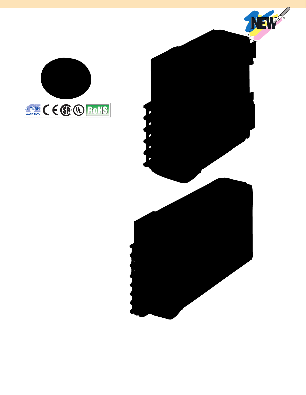
S8VM Series
Starts at
$
101
l Slim DIN Rail Mounting Units
Help Downsize Machine Panels
l Power Capacities from 15 to
1500 W; Four Output Voltages
5, 12, 15 and 24V
l Overvoltage Protection
(Standard) of 105 to 160% Rated
Load Current
l Unique Undervoltage Alarm
Function Makes Fault Diagnosis
Easier: Identifies Difference
Between a Momentary Power
Failure, Output Short-Circuit,
and Trouble with Power Supply
l Universal Supply Voltage
(85 to 264 Vac; 50/60 Hz)
l Terminal Block Protects Fingers
Against Electric Shock
l Power Factor Correction
Function Standard
l Class 1, Div 2 Rated for
Hazardous Areas
S8VM-01524CD, $101,
shown smaller than
actual size.
The compact S8VM switching power
supplies offer a uniform height that
simplifies panel design by using a consistent
panel duct height for all models. The S8VM
Series features an undervoltage alarm that
shortens onsite troubleshooting by signaling
when voltage falls and indicating the cause.
This feature, unique among power supplies
currently available, uses combinations of
LEDs to indicate whether voltage loss is due
to a momentary power interruption, an
overload, or a drop as the power supply
itself loses voltage due to aging.
The S8VM is dramatically more compact
(40% smaller) than other power supply
models, and is currently available in ratings
from 15 to 1500 W and voltage capacities
from 5 to 24V, making it suitable for
installation in a wide variety of original
equipment with varying power requirements.
Size reduction does not restrict use in
M-1
S8VM-15024CD, $235, shown
smaller than actual size.
high-temperature environments, and the
S8VM can operate at 100% load rate even at
temperatures of 50°C (122ºF). The S8VM
meets global environmental and safety
standards, including containing no lead to
meet requirements of Europe’s RoHS,
making it suitable for equipment to be
shipped overseas.
Page 2
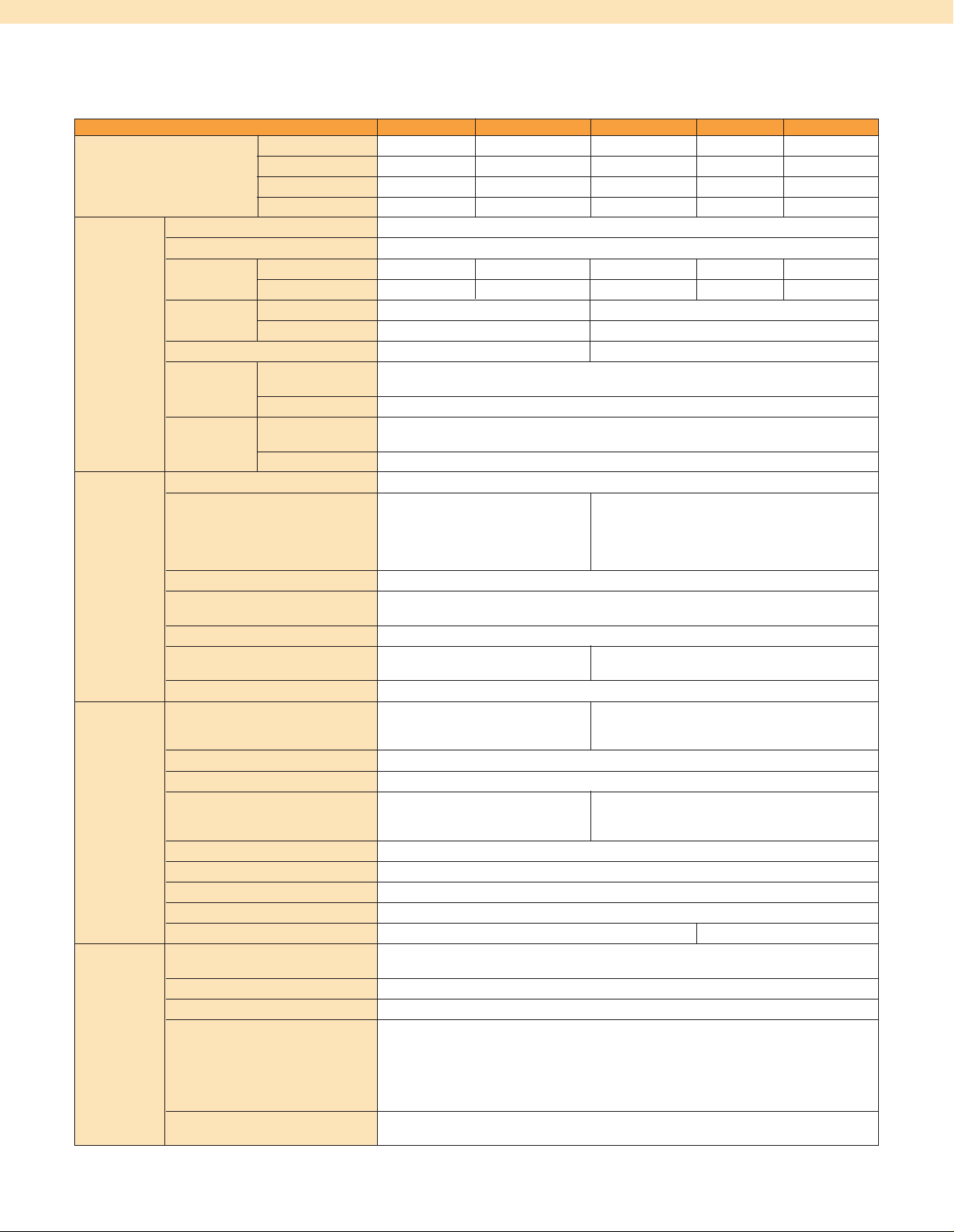
SPECIFICATIONS
RATINGS/CHARACTERISTICS (15, 30, 50, 100 AND 150 W)
POWER RATING 15 W 30 W 50 W 100 W 150 W
Efficiency 5V Models 75% min 75% min 80% min 81% min 81% min
12V Models 78% min 79% min 79% min 81% min 81% min
15V Models 78% min 79% min 79% min 81% min 81% min
24V Models 80% min 81% min 80% min 82% min 83% min
Input Voltage
Frequency
Current 100V Input 0.5 A max 0.9 A max 0.8 A max 1.4 A max 2.0 A max
Power Factor
Harmonic Current Emissions – Conforms to EN 61000-3-2
Leakage 100V Input 0.4 mA max (at rated output)
Current
Inrush 100V Input 17.5 A max [for cold start at 25°C (77ºF)]
Current
Output Voltage Adjustment Range
Ripple 3.2% (p-p) max (5V), 1.5%
Input Variation Influence 0.4% max (at 85 to 264 Vac input, 100%)
Load Variation Influence
(Rated Input Voltage) 0.8% max (with rated input, 0 to 100% load)
Temperature Variation Influence
Start Up Time 1100 ms max (at rated 800 ms max (at rated
Hold Time 20 ms typ. (15 ms min) (at rated input/output voltage)
Additional
Overload Protection 105 to 160% of rated load
functions current, voltage drop,
Overvoltage Protection
Undervoltage Alarm Indication Yes [color: yellow (DC LOW1), red (DC LOW2)] (S8VM-@@@24A@/P@ only)
Undervoltage Alarm Output No Yes (S8VM-@@@24A@/P@ only)
Power Failure Alarm Indication
Power Failure Alarm Output No
Series Operation Yes
Parallel Operation No
Remote Sensing Function No Yes
Other
Ambient Operating Temperature
Storage Temperature -25 to 65°C (-13 to 149ºF)
Ambient Operating Humidity 30 to 85% (storage humidity: 25 to 90%)
Dielectric Strength 3.0 kVac for 1 min (between all inputs and outputs; detection current:
Insulation Resistance 100 MΩ min (between all outputs and all inputs, PE/FG terminals)
Note: See page M-3 for footnotes 1-7.
1
1
100 to 240 Vac (85 to 264 Vac)
50/60 Hz (47 to 63 Hz)
200V Input 0.25 A max 0.45 A max 0.4 A max 0.7 A max 1.0 A max
100V Input – 0.98 min
200V Input – 0.94 min
200V Input 0.75 mA max (at rated output)
200V Input 35 A max [for cold start at 25°C (77ºF)]
2
-20 to 20% (with V. ADJ) (S8VM-@@@24A@/P@: -10 to 20%)
(p-p) max (12 V), 1.2% (p-p)
max (15V), 1.0% (p-p) max
(24V), (at rated input/output
voltage)
3.2% (p-p) max (5V), 1.5%
(p-p) max (12V), 1.2% (p-p) max
(15V), 0.75% (p-p) max (24V),
(at rated input/output voltage)
0.02%/°C (32ºF) max
input/output voltage) input/output voltage)
105 to 160% of rated load current, voltage
drop (12, 15, and 24V), voltage drop,
intermittent, automatic reset
3
Yes
intermittent (5V), automatic reset
(transistor output), 30 Vdc max,
50 mA max
7
No
Refer to the derating curve in engineering data (15, 30, 50, 100, and
150 W models) (with no icing or con-densation)
20 mA) 2.0 kVac for 1 min (between all inputs and PE/FG terminals;
detection current: 20 mA) 500 Vac for 1 min (between all outputs and
PE/FG terminals; detection current: 100 mA) 500 Vac for 1 min (between all
outputs (except the detection output terminals) and detection output
terminals; de-tection current: 20 mA) (S8VM-@@@24A@/P@ only)
at 500 Vdc
M-2
Page 3
99.5
(3.9)
15 max
(0.5)
14
(0.6)
109.4
(4.3)
46.2
(1.8)
84.5
(3.3)
3.5 max
(0.1)
35.1
(1.4)
5.4 (Sliding: 9 max)
15 max
(0.5)
14
(0.6)
3.5 max
(0.1)
36.6
(1.4)
164.5
(6.5)
174.4
(6.8)
5.4 (Sliding: 9 max)
84.5
(3.3)
46.2
(1.8)
15 max
(0.5)
124.5
(4.9)
14
(0.6)
84.5
(3.3)
134.4
(5.3)
46.2
(1.8)
35.1
(1.4)
5.4 (Sliding: 9 max)
3.5 max
(0.1)
84.5
(3.3)
46.2
(1.8)
84.5
(3.3)
94.4
(3.7)
15 max
(0.5)
35.1
(1.4)
3.5 max
(0.1)
14
(0.6)
5.4 (Sliding: 9 max)
SPECIFICATIONS (CONTINUED)
RATINGS/CHARACTERISTICS (15, 30, 50, 100, AND 150 W)
POWER RATING 15 W 30 W 50 W 100 W 150 W
Other Vibration Resistance 10 to 55 Hz, 0.375 mm single amplitude for 2 hours each in X, Y,
Shock Resistance 150 m/s2, 3 times each in ±X, ±Y, ±Z directions
Output Indicator Yes (color: green)
EMI Conducted Emission Conforms to EN61204-3 EN55011 Class B and based on FCC Class B
Radiated Emission
EMS Conforms to EN61204-3 high severity levels
Approved Standards UL: UL508 (Listing), UL60950-1, UL1604 (Class I/Division 2, Listing) CSA:
6
Weight
1. Do not use the inverter output for the power supply. inverters with an output frequency of 50/60 Hz are available, but the rise in the internal
temperature of the power supply may result in ignition or burning.
2. If the V. ADJ adjuster is turned, the voltage will increase by more than +20% of the voltage adjustment range.
When adjusting the output voltage, confirm the actual output voltage from the power supply and be sure that the load is not damaged.
3. To reset the protection, turn OFF the input power for three minutes or longer and then turn it back ON.
4. Conducted Emissions: The noise value is affected by factors such as the wiring method. The Power Supply conforms to Class B when the
aluminum plate is laid under the power supply. For 15 W models, insert a clamp filter (ZCAT2436-1330 by TDK: 50 Ω min. [50 to 500 MHz], or
the equivalent) in the output wire to reduce noise.
5. Radiated Emissions: The noise value is affected by factors such as the wiring method. The power supply conforms to Class B when the
aluminum plate is laid under the power supply. For 150 W models, insert a clamp filter (ZCAT2017-0930 by TDK: 35 Ω min. [50 to 500 MHz],
or the equivalent) in the input wire to reduce noise.
6. The weight indicated is for bottom mounting, open-frame models.
7. A@: Sinking type (NPN)
P@: Sourcing type (PNP)
g (oz)
and Z directions
Conforms to EN61204-3 EN55011 Class B
5
cUL: C22.2 No.14, No.213 (Class I/Division 2), cUR: No. 60950-1 EN:
EN50178, EN60950-1 SELV (EN60950-1) According to VDE0160/P100
SEMI-F47 (200 Vac input)
180 (6) max
220 (8) max 290 (10) max
460 (16) max 530 (19) max
4
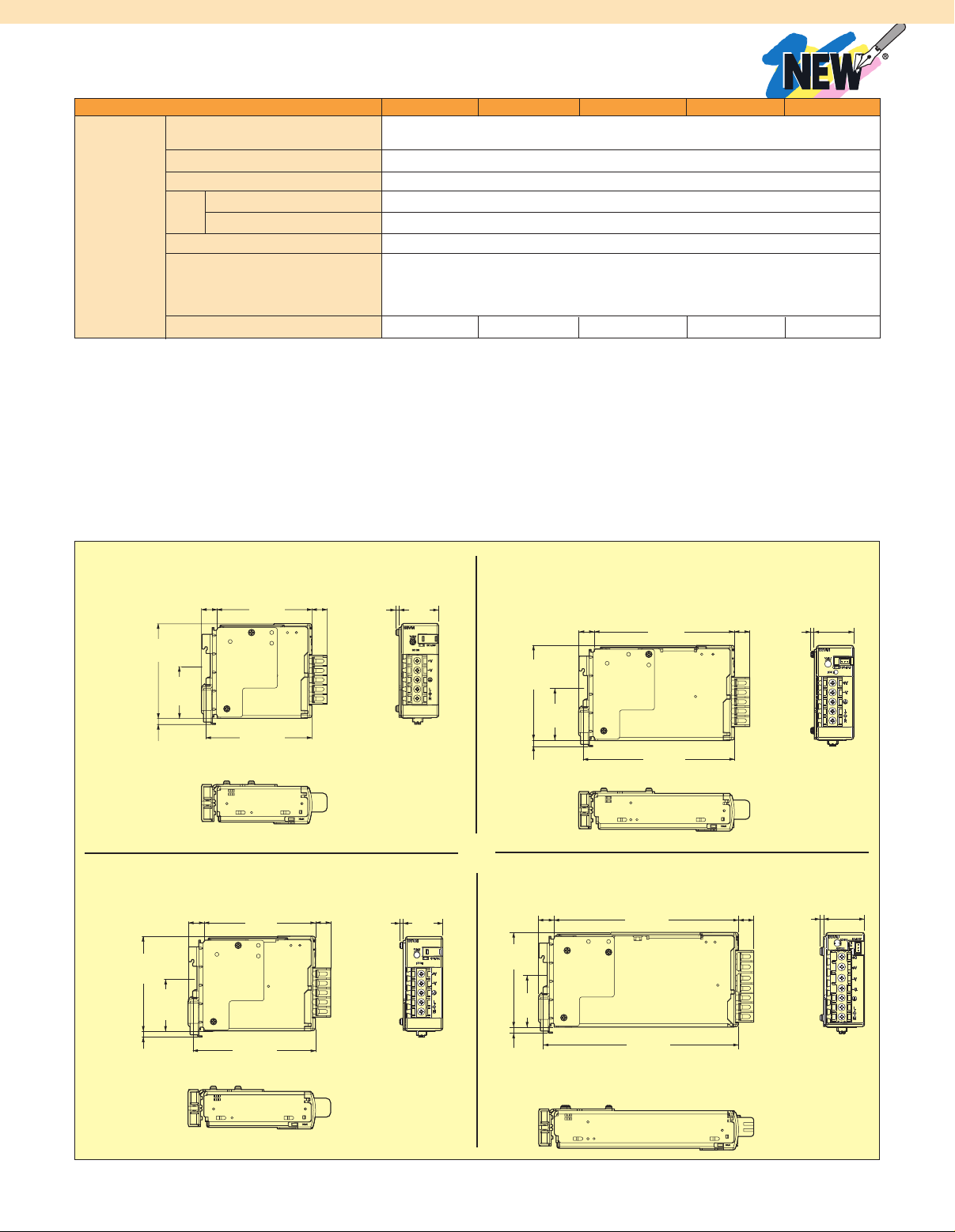
S8VM-015
S8VM-030
S8VM-050
Dimensions: mm (in)
S8VM-100
M-3
Page 4

SPECIFICATIONS
RATINGS/CHARACTERISTICS (300, 600 AND 1500 W)
POWER RATING 300 W 600 W 1500 W
Efficiency 5V Models 77% min 77% min –
12V Models 78% min 79% min –
15V Models 79% min 80% min –
24V Models 81% min 81% min 82% min
Input Voltage
Frequency
Current 100V Input 4.0 A max (5V) 4.3 A max 8.0 A max 20.0 A max
Power Factor 100V input 0.98 min 0.97 min
Harmonic Current Emissions Conforms to EN61000-3-2
Leakage 100V Input 0.4 mA max 1.5 mA max
Current
Inrush 100V Input 20 A max [for cold start at 25°C (77ºF)]
Current
Output Voltage Adjustment Range2-20 to 20% (with V. ADJ)
Ripple 3.8% (p-p) max (5V), 2.0% (p-p) max (12V),
Input Variation Influence 0.4% max (at 85 to 264 Vac input, 100%)
Load Variation Influence
(Rated Input Voltage) 0.6% max (with rated input, 0 to 100% load)
Temperature Variation Influence
Start up Time 1000 ms max (at rated input/output voltage)
Hold Time 20 ms typ. (15 ms min) (at rated input/output voltage)
Additional
Overload Protection
Functions
Overvoltage Protection Yes
Overheat Protection Yes
Undervoltage Alarm Indication
Undervoltage Alarm Output
Power Failure Alarm Indication
Power Failure Alarm Output
Series Operation Yes
Parallel Operation Yes (up to 2 units)
Remote Sensing Function Yes
Remote Control Function Yes
Other Ambient Operating Refer to the derating curve in engineering data (300, 600, 1500 W models)
Temperature (with no icing or condensation)
Storage Temperature -25 to 65°C (-13 to 149ºF)
Ambient Operating Humidity 30 to 85% (storage humidity: 25 to 90%)
Note: See page M-5 for footnotes 1-6.
1
1
100 to 240 Vac (85 to 264 Vac) 100 to 240 Vac (85 to 265 Vac)
50/60 Hz (47 to 63 Hz)
(12, 15, and 24V) (5V) 8.3 A max
(12, 15, and 24V)
200V Input
2.0 A max (5V) 2.2 A max
4.0 A max (5V) 11.0 A max
(12, 15, and 24V) 4.2 A max (12,
15, and 24V)
200V input 0.94 min 0.93 min
200V Input 0.75 mA max 1.5 mA max
200V Input 40 A max [for cold start at 25°C (77ºF)]
2.0% (p-p) max (15V), 1.25% (p-p)
max (24V), (at rated input/output voltage)
1.25% (p-p) max6, (at rated
input/output voltage)
0.02%/°C (32ºF) max
105 to 160% of rated load current (5,
12, and 15V), 120 to 160% of rated
load current (S8VM-30024C), 115 to 160%
of rated load current (S8VM-60024C), voltage
drop (12, 15, and 24V), voltage drop,
intermittent (5V), automatic reset )
3
3
105 to 160% of rated load
(100
Vac
), 155 to 200%
load current (200 Vac), voltage
drop, automatic reset (turns OFF
when continuous for 5 s min)
No
No
Yes (color: red)
Yes (transistor output), 30 Vdc max, 50 mA max
current
of rated
3
M-4
Page 5

SPECIFICATIONS (CONTINUED)
45.6
(1.8)
46.2
(1.8)
84.5
(3.3)
15 max
(0.5)
14
(0.6)
3.5 (0.1)
max
164.5
(6.5)
174.4
(6.8)
5.4 (0.2) (Sliding: 9 max)
RATINGS/CHARACTERISTICS (300, 600 AND 1500 W)
POWER RATING
Other Dielectric
Strength outputs; detection current: 20 mA) 2.0 kVac
Insulation 100 MΩ min (between all outputs and all 100 MΩ min (between all
Resistance inputs, PE terminals) at 500 Vdc outputs and all in-puts, FG
Vibration 10 to 55 Hz, 0.375 mm single 10 to 55 Hz, 0.15 mm single
Resistance amplitude for 2 hours each in X, amplitude for 2 hours each in X,
Shock Resistance 150 m/s2, 3 times each in ±X, ±Y, ±Z directions
Output Indicator Yes (color: green)
EMI Conducted Conforms to EN61204-3 EN55011 Class B Conforms to EN61204-3
Emission and based on FCC Class B EN55011 Class A and based on
Radiated Conforms to EN61204-3 EN55011 Class B Conforms to EN61204-3
Emission EN55011 Class A
EMS Conforms to EN61204-3 high severity levels
Approved Standards
7
Weight g (oz) 1100 (39) max 1700 (60) max 3800 (134) max
1. Do not use the inverter output for the power supply. Inverters with an output frequency of 50/60 Hz are available, but the rise in the internal
temperature of the power pupply may result in ignition or burning.
2. If the V. ADJ adjuster is turned, the voltage will increase by more than +20% of the voltage adjustment range. When adjusting the output
voltage, confirm the actual output voltage from the power supply and be sure that the load is not damaged.
3. To reset the protection, turn OFF the input power for three minutes or longer and then turn it back ON. Alternatively, turn OFF the remote
control signal and then turn it back ON again.
4. Conducted Emissions: The noise value is affected by factors such as the wiring method. The power supply conforms to Class B when the
aluminum plate is laid under the power supply. For 600 W models, insert a clamp filter [ZCAT3035-1330 by TDK: 100 Ω min. (50 to 500 MHz),
or the equivalent] in the input wire, and ring core [HF60T38X14X22 by TDK: 16 Ω typ. (1 MHz), 46 Ω typ. (10 MHz) , or the equivalent] in the
output wire to reduce noise.
5. Radiated Emissions: The noise value is affected by factors such as the wiring method. The power supply conforms to Class A when the
aluminum plate is laid under the power supply (1500 W models).
6. The measuring method conforms to JEITA standard RC-9131A.
7. The power supply will not conform to safety standards if the customer replaces the fan.
300 W 600 W 1500 W
3.0 kVac for 1 min (between all inputs and
3.0 k Vac for 1 min (between
all inputs and outputs;
for 1 min (between all inputs and PE
terminals; detection current: 20 mA) 500 Vac
for 1 min (between all outputs and
PE terminals; detection current: 100 mA)
100 Vac for 1 min (between all
outputs and RC terminals; detection current:
100 mA) 500 Vac for 1 min (between
all outputs and PF terminals;
detection current: 20 mA)
detection current: 20 mA)
2.0 k Vac for 1 min (between
all inputs and FG terminals;
detection current: 20 mA)
500 Vac for 1 min (between all
outputs and FG terminals;
detection current: 300 mA)
100 Vac for 1 min (between all
outputs and RC terminals;
detection current: 100 mA)
500 Vac for 1 min (between all
outputs and PF terminals;
detection current: 20 mA)
terminals) at 500 Vdc
Y, and Z directions Y, and Z directions
FCC Class A
UL: UL508 (Recognition) (5, 12, and 15V)
UL508 (Listing) (24V), UL60950-1 UL1604
(Class I/Division 2, Listing) (24V) (pending)
CSA: cUL: C22.2 No.14,
cUR: CSA No. 60950-1 EN: EN50178,
EN60950-1 SEMI-F47 (200 Vac input)
UL: UL508 (Recognition),
UL60950-1 cUR: CSA C22.2
No.14, No. 60950-1 EN:
EN50178, EN60950-1
SEMI-F47 (200 Vac input)
S8VM-150
Dimensions: mm (in)
M-5
Page 6

192 (7.5) max
26 (1.02) max
46 max
(1.8)
101.8 (4.0)
21 (0.8)
20 (0.7)
Four, M4 (depth: 6 max)
Four, M4 (depth: 6 max)
120±0.5 (4.7±0.01)
83.8
(3.2)
60±0.5
(2.3±0.01)
25
(0.99)
110±0.5 (4.3±0.01)
40±0.5
(1.5±0.01)
Mounting Holes
Bottom View
Standard
Mounting
Horizontal
Mounting
Four, 4.5 (0.2) dia.
Four, 4.5 (0.2)dia.
40±0.5
(1.5±0.01)
60±0.5
(2.3±0.01)
120±0.5
(4.7±0.01)
110±0.5
(4.3±0.01)
188 (7.4) max
Four, M4
(depth: 6 max)
Four, M4 (depth: 6 max)
62.5
(2.4)
25 (0.99)
25
(0.99)
22 max
(0.8)
22 max
(0.8)
83.5
(3.2)
60±0.5
(2.3±0.01)
11 (0.4)
10.5 (0.4)
105±0.5(4.1±0.01)
120±0.5(4.7±0.01)
40±0.5
(1.5±0.01)
Mounting Holes
Bottom View
Standard
Mounting
Horizontal
Mounting
Four, 4.5 (0.2)dia.
Four, 4.5 (0.2)dia.
40±0.5
(1.5±0.01)
60±0.5
(2.3±0.01)
120±0.5
(4.7±0.01)
105±0.5
(4.1±0.01)
S8VM-300
S8VM-600
Dimensions: mm (in)
S8VM-60024CD, $855, shown
smaller than actual size.
To Order (Specify Model Number)
MOST POPULAR MODELS HIGHLIGHTED!
MODEL NO. PRICE DESCRIPTION
S8VM-01512CD $101 Power supply, 12 Vdc, 1.3 A
S8VM-01524CD 101 Power supply, 24 Vdc, 0.65 A
S8VM-03012CD 108 Power supply, 12 Vdc, 2.5 A
S8VM-03024CD 108 Power supply, 24 Vdc, 1.3 A
S8VM-05012CD 131 Power supply, 12 Vdc, 4.3 A
S8VM-05024CD 131 Power supply, 24 Vdc, 2.2 A
S8VM-10012CD 186 Power supply, 12 Vdc, 8.5 A
S8VM-10024CD 186 Power supply, 24 Vdc, 4.5 A
S8VM-15012CD 235 Power supply, 12 Vdc, 12.5 A
S8VM-15024CD 235 Power supply, 24 Vdc, 6.5 A
S8VM-30024CD 515 Power supply, 24 Vdc, 12.5 A
S8VM-60024CD 855 Power supply, 24 Vdc, 25 A
Ordering Examples: S8VM-01524CD, power supply, 24 Vdc, 0.65 A, DIN rail mount, $101.
S8VM-05024CD, power supply, 24 Vdc, 2.2 A, DIN rail mount, $131.
M-6
Page 7

One Omega Drive | Stamford, CT 06907 | 1-888-TC-OMEGA (1-888-826-6342) | info@omega.com
EPG05
www.omega.com
UNITED KINGDOM
www. omega.co.uk
Manchester, England
0800-488-488
UNITED STATES
www.omega.com
1-800-TC-OMEGA
Stamford, CT.
CANADA
www.omega.ca
Laval(Quebec)
1-800-TC-OMEGA
GERMANY
www.omega.de
Deckenpfronn, Germany
0800-8266342
Karviná, Czech Republic
FRANCE
www.omega.fr
Guyancourt, France
088-466-342
CZECH REPUBLIC
www.omegaeng.cz
596-311-899
BENELUX
www.omega.nl
Amstelveen, NL
0800-099-33-44
More than 100,000 Products Available!
Temperature
Calibrators, Connectors, General Test and Measurement
Instruments, Glass Bulb Thermometers, Handheld Instruments
for Temperature Measurement, Ice Point References,
Indicating Labels, Crayons, Cements and Lacquers, Infrared
Temperature Measurement Instruments, Recorders Relative
Humidity Measurement Instruments, RTD Probes, Elements
and Assemblies, Temperature & Process Meters, Timers and
Counters, Temperature and Process Controllers and Power
Switching Devices, Thermistor Elements, Probes and
Assemblies,Thermocouples Thermowells and Head and Well
Assemblies, Transmitters, Wire
Flow and Level
Air Velocity Indicators, Doppler Flowmeters, Level
Measurement, Magnetic Flowmeters, Mass Flowmeters,
Pitot Tubes, Pumps, Rotameters, Turbine and Paddle Wheel
Flowmeters, Ultrasonic Flowmeters, Valves, Variable Area
Flowmeters, Vortex Shedding Flowmeters
pH and Conductivity
Conductivity Instrumentation, Dissolved Oxygen
Instrumentation, Environmental Instrumentation, pH
Electrodes and Instruments, Water and Soil Analysis
Instrumentation
Data Acquisition
Auto-Dialers and Alarm Monitoring Systems,
Communication Products and Converters, Data
Acquisition and Analysis Software, Data Loggers
Plug-in Cards, Signal Conditioners, USB, RS232, RS485
and Parallel Port Data Acquisition Systems, Wireless
Transmitters and Receivers
Pressure, Strain and Force
Displacement Transducers, Dynamic Measurement
Force Sensors, Instrumentation for Pressure and Strain
Measurements, Load Cells, Pressure Gauges, Pressure
Reference Section, Pressure Switches, Pressure Transducers,
Proximity Transducers, Regulators,
Strain Gages, Torque Transducers, Valves
Heaters
Band Heaters, Cartridge Heaters, Circulation Heaters,
Comfort Heaters, Controllers, Meters and Switching
Devices, Flexible Heaters, General Test and Measurement
Instruments, Heater Hook-up Wire, Heating Cable
Systems, Immersion Heaters, Process Air and Duct,
Heaters, Radiant Heaters, Strip Heaters, Tubular Heaters
click here to go to the omega.com home page
 Loading...