

Page 1
User’s Guide
Shop online at
omega.com
e-mail: info@omega.com
For latest product manuals:
omegamanual.info
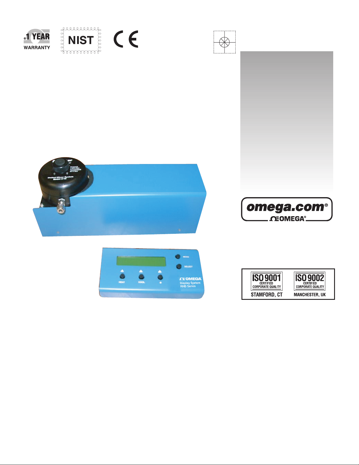
RHB-3 and RHB-4
Dew Point Monitor
Page 2

OMEGAnet®Online Service Internet e-mail
omega.com info@omega.com
U.S.A.:
ISO 9001 Certified
Canada:
For immediate technical or application assistance:
U.S.A. and Canada:
Servicing North America:
One Omega Drive, P.O. Box 4047
Stamford, CT 06907-0047
TEL: (203) 359-1660 FAX: (203) 359-7700
e-mail: info@omega.com
976 Bergar
Laval (Quebec) H7L 5A1, Canada
TEL: (514) 856-6928 FAX: (514) 856-6886
e-mail: info@omega.ca
Sales Service: 1-800-826-6342 / 1-800-TC-OMEGA
Customer Service: 1-800-622-2378 / 1-800-622-BEST
Engineering Service: 1-800-872-9436 / 1-800-USA-WHEN
TELEX: 996404 EASYLINK: 62968934 CABLE: OMEGA
®
®
®
Mexico:
Benelux:
Czech Republic:
France:
Germany/Austria:
United Kingdom:
ISO 9002 Certified
En Espan˜ ol: (001) 203-359-7803 e-mail: espanol@omega.com
FAX: (001) 203-359-7807 info@omega.com.mx
Servicing Europe:
Postbus 8034, 1180 LA Amstelveen, The Netherlands
TEL: +31 (0)20 3472121 FAX: +31 (0)20 6434643
Toll Free in Benelux: 0800 0993344
e-mail: sales@omegaeng.nl
Frystatska 184, 733 01 Karviná, Czech Republic
TEL: +420 (0)59 6311899 FAX: +420 (0)59 6311114
Toll Free: 0800-1-66342 e-mail: info@omegashop.cz
11, rue Jacques Cartier, 78280 Guyancourt, France
TEL: +33 (0)1 61 37 2900 FAX: +33 (0)1 30 57 5427
Toll Free in France: 0800 466 342
e-mail: sales@omega.fr
Daimlerstrasse 26, D-75392 Deckenpfronn, Germany
TEL: +49 (0)7056 9398-0 FAX: +49 (0)7056 9398-29
Toll Free in Germany: 0800 639 7678
e-mail: info@omega.de
One Omega Drive, River Bend Technology Centre
Northbank, Irlam, Manchester
M44 5BD United Kingdom
TEL: +44 (0)161 777 6611 FAX: +44 (0)161 777 6622
Toll Free in United Kingdom: 0800-488-488
e-mail: sales@omega.co.uk
It is the policy of OMEGA Engineering, Inc. to comply with all worldwide safety and EMC/EMI
regulations that apply. OMEGA is constantly pursuing certification of its products to the European New
Approach Directives. OMEGA will add the CE mark to every appropriate device upon certification.
The information contained in this document is believed to be correct, but OMEGA accepts no liability for any
errors it contains, and reserves the right to alter specifications without notice.
WARNING: These products are not designed for use in, and should not be used for, human applications.
Page 3

CONTENTS
TOPIC PAGE
Overview of the RHB-3 and the RHB-4 5
Systems Components 5
Measurement parameters available 6
Available Interfaces 6
ACCUSTAR, self correction feature 6
Theory of Operation 6
Operating from Display 7
Cleaning Mirror 8
Menu Overview 9, 10, 11
Display/Sensor Controls 12
Electrical Connections to Display Module 13
Electrical Connections to the Sensor Chassis 14
RS232 Connection 14, 15
Calibration Analog Outputs 15, 16
Final (NIST) Calibration 16
Page 4

Overview of the RHB-3
The OMEGA® RHB-3 is a chilled mirror monitor and can be used in a wide variety of
applications. It provides accurate and reliable measurements over an extended range for
long periods of time with the new ACCU-Star self-correcting feature.
• Dew/frost point from 22°C to –40°C @ an ambient temperature of 25°C
• Relative humidity from 0.002% to 100%
The RHB-3 offers a remote multifunction display and can display two selectable
measurements simultaneously, while outputting two selectable analog outputs, one
selectable alarm point and any combination of selected measurements on a serial port.
The RHB-3 is a bench top monitor with panel mount capability.
Three sensing configurations of the RHB-3 are available: dew point, temperature and
pressure.
RHB-3 Specifications
Dew Point Range -40°C to 24°C @25°C
Accuracy +/- 0.2°C
Repeatability +/-0.05°C
Hysteresis None
Temperature (optional) 100 Ohm 4 wire PRT 0.00385 Ohm
Pressure (optional) 4-20mA abs. pressure sensor
Analog
RS232
Alarms
Operating Temperature 0 to 60 deg C
Operating Pressure 0-1Mpa
Power 85 to 265Vac 50/60HZ 100W
Weight 5kg
Sensor dimensions
Meter dimensions
Dual 0-5Vdc & 4-20mA
Any parameters
100mA AC/DC Opto-Isolators
360*110*130mm
210*110*30mm
Page 5

Overview of the RHB-4
The Shinyei RHB-4 is a chilled mirror monitor and can be used in a wide
variety of applications. It provides accurate and reliable measurements over an extended
range for long periods of time with the new ACCU-Star self-correcting feature.
• Dew/frost point from 22°C to –60°C @ an ambient temperature of 25°C
• Relative humidity from 0.002% to 100%
The RHB-4 offers a remote multifunction display and can display two selectable
measurements simultaneously, while outputting two selectable analog outputs, one
selectable alarm point and any combination of selected measurements on a serial port.
The RHB-4 is a bench top monitor with panel mount capability.
Three sensing configurations of the RHB-4 are available: dew point, temperature and
pressure.
RHB-4 Specifications
Dew Point Range -55°C to 24°C @25°C
Accuracy +/- 0.2°C
Repeatability +/-0.05°C
Hysteresis None
Temperature (optional) 100 Ohm 4 wire PRT 0.00385 Ohm
Pressure (optional) 4-20mA abs. pressure sensor
Analog
RS232
Alarms
Operating Temperature 0 to 60 deg C
Operating Pressure 0-1Mpa
Power 85 to 265Vac 50/60HZ 100W
Weight 5kg
Sensor dimensions
Meter dimensions
Dual 0-5Vdc & 4-20mA
Any parameters
100mA AC/DC Opto-Isolators
360*110*135mm
210*110*30mm
System Components
The complete system consists of the following items:
• The electronic display
• Dew point sensor
• Interconnecting sensor cable
• AC line cord
• Operators manual
• Certificate of Calibration
• Maintenance Kit
• RS232 cable
Page 6

Measurement parameters available:
Dew Point Degree C or F
Temperature Degree C or F
Pressure kPa, mbar, psia
Relative Humidity %RH
Absolute Humidity PPMv, PPMw, g/m3, grains/lb
Available interfaces are as follows:
• 2 Analog outputs: 0-5V and 4-20mA (all parameters)
• “Analog outputs” may be configured as 0/5 volt and 4/20mA alarms, optional
100mA AC/DC Opto-isolated add-on module available
• Alarm relay: 100mA AC/DC Opto-isolated
• RS-232: Any parameter
• 4-20mA Pressure sensor inputs
• 100 Ohm PRT 4 wire 0.00385 Ohm
Feature:
The ACCU-STAR feature provides automatic contaminations correction allowing
your Dewpoint Monitor to continue providing accurate and reliable measurements over
extended periods of time without having to physically interrupt your measurement
process.
Theory of Operation
Optical condensation hygrometry is a precise technique for determining the water vapor
content in gases by directly measuring dew point or frost temperatures. Using this
technique, a metallic mirror is cooled until it reaches a temperature at which a thin layer
of condensation begins to form on it. The dew layer is detected optically, and the mirror
is held at that temperature. The mirror temperature, measured with a platinum resistance
thermometer, is an accurate indicator of the dew or frost point. Because these
hygrometers are so accurate, they are widely used as a standard in many of the world's
metrology laboratories. The condensate mirror is illuminated with a high-intensity, solid
state, light emitting diode (LED). A photo- detector monitors the LED light reflected
from the mirror. The photo detector is fully illuminated when the mirror is clear of dew,
and it receives less light as dew forms. A separate photo detector is used as a known
reference to compensate for any thermally induced changes in the optical components.
The photo detectors are measured by a microprocessor, the output of the microprocessor
controls the electrical current to the thermoelectric cooler. A high cooler current is sent
when the mirror is dry, causing the mirror to cool toward the dew point. As dew begins to
form on the mirror, less light is reflected, and the current output decreases. A rate
feedback loop within the microprocessor ensures critical response, causing the mirror to
stabilize quickly at a temperature that maintains a thin dew or frost layer on the mirror
surface. A precision thermometer element embedded within the mirror directly monitors
this dew point temperature.
Page 7

Operating from display
Power up
Should read OMEGA Dewpoint system RHB.
Begin power-up Accu-Star
Unit automatically goes into heat mode
Stays in heat until mirror is dry (min 20 sec)
Unit then goes into cool mode until mirror is flooded
Unit heats to clear mirror, and check optics.
Checkpoint: lower right hand of display a star will appear indicating unit is in accustar
mode. If star switches to a DT, clean the mirror.
The ACCU-STAR mode balances the optics, checks the clean mirror condition, if these
two conditions are met unit goes into operate. If the mirror is dirty, it will try to clean it
automatically, if it fails to clean mirror twice the DT letters will appear in the lower left
of the display. After two cycles of cleaning, unit goes into operate mode.
If it is in operate mode and has found a stable dew point, then the letters OK will appear
in the lower left of the display.
Page 8

Cleaning Mirror
Power down
Unscrew sensor cap
Using cotton swab and cleaning solution (provided in the MC Kit), wipe mirror with the
wetted end of the cotton swab, dry mirror with the other end of the cotton swab.
Power unit up and unit will rebalance.
Alternate procedure:
Push heat button,
Using cotton swab and cleaning solution (provided in the MC Kit), wipe mirror with the
wetted end of the cotton swab, dry mirror with the other end of the
swab.
Push * button. Unit will rebalance.
Page 9

Menu
Overview:
To scroll forward through the menu items, press the menu button. To scroll backwards,
press cool. When you see the menu item that you want to change, press select. The
existing setting or units will appear. To scroll forward through the setting or units, press
the menu button. To scroll backwards, press cool. When you see the setting or units that
you want, press select.
To set numbers, scroll up or down using the up or down keys (heat or cool), the
increment can be changed using the incr key (*). In all cases, when the setting is as you
like it, press select.
Main menu choices:
Units Line 1
Selects the Units for top line of display
Units Line 2A
Selects the Units for second line of display
Units Line 2B
Selects the Alternate Units for second line of display, quick switch by
pressing select while the unit is operating.
Units Output 1
Selects the Units for Output channel 1,
Set the LO range (0 volt, 4mA) using the number select procedure.
Set the HI range (5 volt, 20mA) using the number select procedure.
Select Analog or Alarm mode.
Page 10

Units Output 2
Selects the Units for Output channel 2,
Set the LO range (0 volt, 4mA) using the number select procedure.
Set the HI range (5 volt, 20mA) using the number select
procedure.
Select Analog or Alarm mode.
Units Alarm
Selects the Units for the Alarm,
Set the LO range (alarm open) using the number select procedure.
Set the HI range (alarm closed) using the number select
procedure.
Note: Outputs and alarms can be set normal or inverted. When the HI value is lower than
the LO value the analog scaling is inverted. For alarms the range of values between the
HI and LO values is the hysteresis or dead band, for analog outputs it is the linear range.
Units Comm Port
Selects the Units to be output on the COMM port,
Scroll through the Units and press either include or exclude to decide
which units are sent to the COMM port.
Accu* Set up
Set the time interval between automatic ACCU*s.
Select track to have the progress of the ACCU* tracked on the
display and outputs.
Select hold to have the last reading held until the ACCU* is
over.
Scale Pressure
Set the LO range (4mA) of the pressure sensor in kPa, using the number
select procedure.
Set Mol Wt
Set the Molecular weight of the gas you are measuring using the number
select procedure.
Set Average
Set the number of points to average over.
Note: Averaging is only applied when the unit is stable at the dew point.
Non SI Units (Sensor)
Include or exclude Non-SI sensor units from the units scroll.
Set the HI range (20mA) of the pressure sensor in kPa, using the
number select procedure.
Note: pressures are absolute. Also if you do not have a
pressure transducer, you can enter local atmospheric
pressure as the LO and some higher pressure as the HI.
This will then use local pressure in pressure based
calculations.
Page 11

Display/Sensor Controls
When in operation, the second line of the display can be toggled between units 2A and
2B by pressing the select button.
When the Monitor is running, measurements are shown on the left side of lines one and
two of the display. The right hand edge of the display is used for status indication.
Line one status can be clear or show an “A” if the alarm is active.
Line two status can show clear, OK, DT, *, H, C or X
OK shows that the sensor is stable and at the dew point.
DT means that the last ACCU* failed to clean the mirror properly, see mirror cleaning
procedure.
“*“ means that the unit is in ACCU*
H shows that the sensor has been manually placed into heat.
C shows that the sensor has been manually placed in maximum cool.
X shows that the sensor heat pump has been manually turned off.
To manually place the sensor into heat, press the heat button until the word HEAT
appears. This is done to clear the mirror of dew.
To manually place the sensor into cool, press the cool button until the word COOL
appears. This is done to cover the mirror with dew.
To exit either heat or cool, press the same button again.
To manually place the sensor into ACCU* press the star button.
To shut down the heat pump, press heat, until the word HEAT appears, than press cool
until OFF appears.
To reactivate the heat pump, press either heat or cool until ON appears.
Page 12

Electrical connections to the display module
The Cable to the Sensor chassis plugs in here.
To make your own longer cable, connect
with the terminals on the chassis. Make sure that the
Dout (Data out) from the chassis goes to the Din (Data in)
Of the display module, and vice versa.
When the lock pins are shorted together the buttons on the display are active.
If the shorting plug is removed, the module is locked.
Plug into the 9600 Baud RS-232 port here using the 9 pin to stereo adaptor cable
included with RHB-4.
Alarm terminals, 300 V AC/DC, 100 mA max, opto isolated MOSFET relay.
4-20 mA source for channel 1
0-5volt output channel 1
0-5 volt or 4-20 mA return
4-20 mA source for channel 2
0-5volt output channel 2
0-5 volt or 4-20 mA return
The optional output alarm isolator module connects to the I
(out),V(out) and G(nd)
terminals of either output 1 and(or) 2 to provide (an) additional alarm(s).
Page 13

Electrical connections to the sensor chassis
Reserved for future use, do not connect.
The Cable to the Sensor chassis plugs in here.
To make your own longer cable, connect
with the terminals on the chassis. Make sure that the
Dout (Data out) from the chassis goes to the Din (Data in)
Of the display module, and vice versa.
Connect the + terminal of Pressure transducer here, (4-20mA V+)
Connect the - terminal of Pressure transducer here, (4-20mA V-)
Connect pressure transducer and/or Temperature sensor shield
here.
Connect two wires from same side of 100Ohm PRT here.
Connect two wires from other side of 100Ohm PRT here.
RS232 Connection
Connecting and using the Monitor RS-232 output
The Monitor includes an RS-232 output on the Display Module. The RS-232 port is a
3.5mm round connector which can be used with the cable supplied with your unit.
The choice of information transmitted is selected from the menu on the display module,
and can include any combination of humidity, temperature or pressure units available
from the system. In addition the RS-232 port will send a status word including
information about the control status, mirror cleanliness, and any buttons that have been
pressed, and lastly the hours left until the unit enters an ACCU self cleaning cycle. The
data is sent in a CSV format (comma separated variable) which can be imported directly
into many software packages such as Microsoft Excel.
The data is transmitted at 9600 BAUD, 8 Bit, 1 Stop Bit, No flow control, no parity. Any
Microsoft Windows (version 3.11 and up) based system with a serial port can access this
data using a standard program included in Windows called HyperTerminal. This is
generally found in “windows\accessories\communications”. Please refer to your
Page 14

computer help files for the correct configuration of your computer serial port. After your
computer is correctly configured you will see a data stream such as:
C DP= 32.3607 ,PPMw= 32524.1328 ,gr/#= 227.6689 ,00001100 ,24.
C DP= 33.5534 ,PPMw= 34905.6015 ,gr/#= 244.3392 ,00001100 ,24.
C DP= 34.7088 ,PPMw= 37366.4843 ,gr/#= 261.5653 ,00001100 ,24.
C DP= 35.8230 ,PPMw= 39892.1250 ,gr/#= 279.2448 ,00001100 ,24.
C DP= 36.8813 ,PPMw= 42438.3515 ,gr/#= 297.0684 ,00001100 ,24.
C DP= 37.9010 ,PPMw= 45035.6250 ,gr/#= 315.2493 ,00001100 ,24.
C DP= 38.8769 ,PPMw= 47661.3281 ,gr/#= 333.6293 ,00001100 ,24.
C DP= 39.8022 ,PPMw= 50284.4218 ,gr/#= 351.9909 ,00001100 ,24.
C DP= 40.6960 ,PPMw= 52948.1953 ,gr/#= 370.6373 ,00001100 ,24.
C DP= 41.5535 ,PPMw= 55629.8671 ,gr/#= 389.4090 ,00001100 ,24.
C DP= 42.3635 ,PPMw= 58282.5390 ,gr/#= 407.9777 ,00001100 ,24.
The first part of each line transmits the units that you have selected.
The code 00001100 is the status code.
24 is the number of hours left before the next ACCU cycle.
The Status word at the end of the RS-232 string is a Binary word, (BIT7>> 00001100
<<BIT0)
Bit7=ACCU* button pressed,
Bit6=Heatpump OFF
Bit5=COOL ON
Bit4=HEAT ON
Bit3=System is in ACCU*
Bit2=Air Temp PRT OPEN or not Attached
Bit1=System IN CONTROL
Bit0=Dirty Mirror
Calibrating the Monitor analog outputs
The Analog outputs on the Monitor are both 0-5volts and 4-20mA outputs, on adjacent
terminals for each output, (output#1, output#2, etc.). The ranges for the outputs may be
set from the display, using the “SET OUTPUT(X)” menu. The 0-5 volt outputs are
derived from an internal voltage reference and no calibration is necessary or possible.
The 4-20mA outputs are derived from the 0-5volt outputs and may be calibrated at the
4mA and 20mA values.
To calibrate the 4-20mA output(x), first set the output(x) to a range where the output
should be at 4mA such as DP C , LO= -100°C , HI= -120°C , Analog. With these settings
the output should be at 4mA unless the dew point being measured is below –100°C. Then
adjust the 4mA adjustment pot until the output is 4mA.
Next set the output(x) range so that the output should be 20mA, such as LO = -120°C and
HI= -100°C. This should generate 20mA unless the dew point is below –100°C. Then
adjust the 20mA adjustment pot until the output is 20mA.
The output adjustment pots are found on the display module. They are labeled as follows.
Output #1 4mA, R33 Output#1 20mA, R32
Output #2 4mA, R21 Output#2 20mA, R19
The last pot, R1 is used to adjust the display contrast.
Page 15

Final Calibration
Final Calibration is a test for accuracy where the unit under test is compared against a
NIST transfer standard at a number of different dew points/frost points. A dew
point/frost point generator will create a desired dew point/frost point and will provide a
sample flow at 1L/min to the units under test and the transfer standard. Typically, the
units will be connected in series but should be connected in parallel when testing more
than one unit.
A typical set of test points for a 2 stage dew point monitor is: 15°C, 0°C, -20°C,-30°,
-40°C but can be customized to its application.
The only adjustment that can be made during final calibration is the cleaning of the
mirror and the display unit will indicate if the mirror is dirty by blinking the letters ‘DT’.
See the section (page 7) on cleaning the mirror.
Page 16

Dry Bulb
2 Stage
3 Stage
20 40 60 80
0
Ambient Temp (°C)
-20
RHB-3 (2-stage) and RHB-4 (3-stage) Measurement Range
80
-20
-40
-60
-80
0
20
40
60
Measurement
-40
-100
Page 17

WARRANTY/DISCLAIMER
OMEGA ENGINEERING, INC. warrants this unit to be free of defects in materials and workmanship for a
period of 13 months from date of purchase. OMEGA’s WARRANTY adds an additional one (1) month
grace period to the normal one (1) year product warranty to cover handling and shipping time. This
ensures that OMEGA’s customers receive maximum coverage on each product.
If the unit malfunctions, it must be returned to the factory for evaluation. OMEGA’s Customer Service
Department will issue an Authorized Return (AR) number immediately upon phone or written request.
Upon examination by OMEGA, if the unit is found to be defective, it will be repaired or replaced at no
charge. OMEGA’s WARRANTY does not apply to defects resulting from any action of the purchaser,
including but not limited to mishandling, improper interfacing, operation outside of design limits,
improper repair, or unauthorized modification. This WARRANTY is VOID if the unit shows evidence of
having been tampered with or shows evidence of having been damaged as a result of excessive corrosion;
or current, heat, moisture or vibration; improper specification; misapplication; misuse or other operating
conditions outside of OMEGA’s control. Components in which wear is not warranted, include but are not
limited to contact points, fuses, and triacs.
OMEGA is pleased to offer suggestions on the use of its various products. However,
OMEGA neither assumes responsibility for any omissions or errors nor assumes liability for any
damages that result from the use of its products in accordance with information provided by
OMEGA, either verbal or written. OMEGA warrants only that the parts manufactured by the
company will be as specified and free of defects. OMEGA MAKES NO OTHER WARRANTIES OR
REPRESENTATIONS OF ANY KIND WHATSOEVER, EXPRESSED OR IMPLIED, EXCEPT THAT OF
TITLE, AND ALL IMPLIED WARRANTIES INCLUDING ANY WARRANTY OF MERCHANTABILITY
AND FITNESS FOR A PARTICULAR PURPOSE ARE HEREBY DISCLAIMED. LIMITATION OF
LIABILITY: The remedies of purchaser set forth herein are exclusive, and the total liability of
OMEGA with respect to this order, whether based on contract, warranty, negligence,
indemnification, strict liability or otherwise, shall not exceed the purchase price of the
component upon which liability is based. In no event shall OMEGA be liable for
consequential, incidental or special damages.
CONDITIONS: Equipment sold by OMEGA is not intended to be used, nor shall it be used: (1) as a “Basic
Component” under 10 CFR 21 (NRC), used in or with any nuclear installation or activity; or (2) in medical
applications or used on humans. Should any Product(s) be used in or with any nuclear installation or
activity, medical application, used on humans, or misused in any way, OMEGA assumes no responsibility
as set forth in our basic WARRANTY/DISCLAIMER language, and, additionally, purchaser will indemnify
OMEGA and hold OMEGA harmless from any liability or damage whatsoever arising out of the use of the
Product(s) in such a manner.
RETURN REQUESTS/INQUIRIES
Direct all warranty and repair requests/inquiries to the OMEGA Customer Service Department. BEFORE
RETURNING ANY PRODUCT(S) TO OMEGA, PURCHASER MUST OBTAIN AN AUTHORIZED RETURN
(AR) NUMBER FROM OMEGA’S CUSTOMER SERVICE DEPARTMENT (IN ORDER TO AVOID
PROCESSING DELAYS). The assigned AR number should then be marked on the outside of the return
package and on any correspondence.
The purchaser is responsible for shipping charges, freight, insurance and proper packaging to prevent
breakage in transit.
FOR W
following information available BEFORE
contacting OMEGA:
1. Purchase Order number under which the product
2. Model and serial number of the product under
3. Repair instructions and/or specific problems
OMEGA’s policy is to make running changes, not model changes, whenever an improvement is possible. This affords
our customers the latest in technology and engineering.
OMEGA is a registered trademark of OMEGA ENGINEERING, INC.
© Copyright 2004 OMEGA ENGINEERING, INC. All rights reserved. This document may not be copied, photocopied,
reproduced, translated, or reduced to any electronic medium or machine-readable form, in whole or in part, without the
prior written consent of OMEGA ENGINEERING, INC.
ARRANTY RETURNS, please have the
was PURCHASED,
warranty, and
relative to the product.
FOR NON-WARRANTY REPAIRS,
for current repair charges. Have the following
information available BEFORE contacting OMEGA:
1. Purchase Order number to cover the COST
of the repair,
2. Model and serial number of the product, and
3. Repair instructions and/or specific problems
relative to the product.
consult OMEGA
Page 18

W
here Do I Find Everything I Need for
Process Measurement and Control?
OMEGA…Of Course!
Shop online at omega.com
TEMPERATURE
䡺⻬
Thermocouple, RTD & Thermistor Probes, Connectors, Panels & Assemblies
䡺⻬
Wire: Thermocouple, RTD & Thermistor
䡺⻬
Calibrators & Ice Point References
䡺⻬
Recorders, Controllers & Process Monitors
䡺⻬
Infrared Pyrometers
PRESSURE, STRAIN AND FORCE
䡺⻬
Transducers & Strain Gages
䡺⻬
Load Cells & Pressure Gages
䡺⻬
Displacement Transducers
䡺⻬
Instrumentation & Accessories
FLOW/LEVEL
䡺⻬
Rotameters, Gas Mass Flowmeters & Flow Computers
䡺⻬
Air Velocity Indicators
䡺⻬
Turbine/Paddlewheel Systems
䡺⻬
Totalizers & Batch Controllers
pH/CONDUCTIVITY
䡺⻬
pH Electrodes, Testers & Accessories
䡺⻬
Benchtop/Laboratory Meters
䡺⻬
Controllers, Calibrators, Simulators & Pumps
䡺⻬
Industrial pH & Conductivity Equipment
DATA ACQUISITION
䡺⻬
Data Acquisition & Engineering Software
䡺⻬
Communications-Based Acquisition Systems
䡺⻬
Plug-in Cards for Apple, IBM & Compatibles
䡺⻬
Datalogging Systems
䡺⻬
Recorders, Printers & Plotters
HEATERS
䡺⻬
Heating Cable
䡺⻬
Cartridge & Strip Heaters
䡺⻬
Immersion & Band Heaters
䡺⻬
Flexible Heaters
䡺⻬
Laboratory Heaters
ENVIRONMENTAL
MONITORING AND CONTROL
䡺⻬
Metering & Control Instrumentation
䡺⻬
Refractometers
䡺⻬
Pumps & Tubing
䡺⻬
Air, Soil & Water Monitors
䡺⻬
Industrial Water & Wastewater Treatment
䡺⻬
pH, Conductivity & Dissolved Oxygen Instruments
M4082/0605
 Loading...