

Page 1

Model RHB-1500-C
Portable Dew Point Monitor
MODEL RHB-1500-C
Portable Dew Point Monitor
MADE IN
OPERATOR’S MANUAL
Shop Online: omega.com
E-Mail: info@omega.com
1
Page 2

TABLE OF CONTENTS
1.0 GENERAL DESCRIPTION
2.0 SAMPLE CONNECTIONS
2.1 SAMPLE CONNECTIONS
2.2 ALARM RELAY CONNECTIONS
2.3 ANALOG OUTPUT CONNECTIONS
2.4 SERIAL PORT OUTPUT CONNEECTIONS
3.0 FUNCTIONAL DESCRIPTION
Model RHB-1500-C
Portable Dew Point Monitor
3.1 DISPLAY
3.2 MABC BUTTON
3.3 CLEAN MIRROR RELAY
3.4 FLOW CONTROL VALVE
3.5 ALARM RELAY OUTPUT
3.6 ANALOG OUTPUT
3.7 DISPLAY “SCAN” BUTTON
4.0 SETUP
4.1 ALARM SET POINTS
4.2 ABC INTERVAL
5.0 MAINTENANCE
5.1 ROUTINE MAINTENANCE
5.2 MIRROR CLEANING SCHEDULE
5.3 MIRROR CLEANING PROCEDURE
6.0 SPECIFICATIONS
7.0 APPENDICES
2
Page 3
Model RHB-1500-C
Portable Dew Point Monitor
1.0 GENERAL DESCRIPTION
The Model RHB-1500-C Battery Powered DPM is an integrated system including
a microprocessor-based instrument, a chilled mirror dew point sensor, a sample
flow meter and associated tubing and fittings.
The Standard Instrument includes: (Other options available)
• An eight-digit, alphanumeric, LED display to report the dew point and system status.
• Periodic sensor balance check.
• Programmable Alarm Set Point with visual and contact closure alarm indications.
• Two SPDT (Form C) Alarm Relay.
• 4 - 20mA analog output.
3
Page 4

Portable Dew Point Monitor
2.0 SAMPLE CONNECTIONS
2.1 SAMPLE CONNECTIONS
The sample may be brought to the instrument with ¼" copper, stainless steel, or
plastic tubing and terminated in a ¼" female fitting.
Connect the sample supply line to the ¼" tubing fitting located on the panel
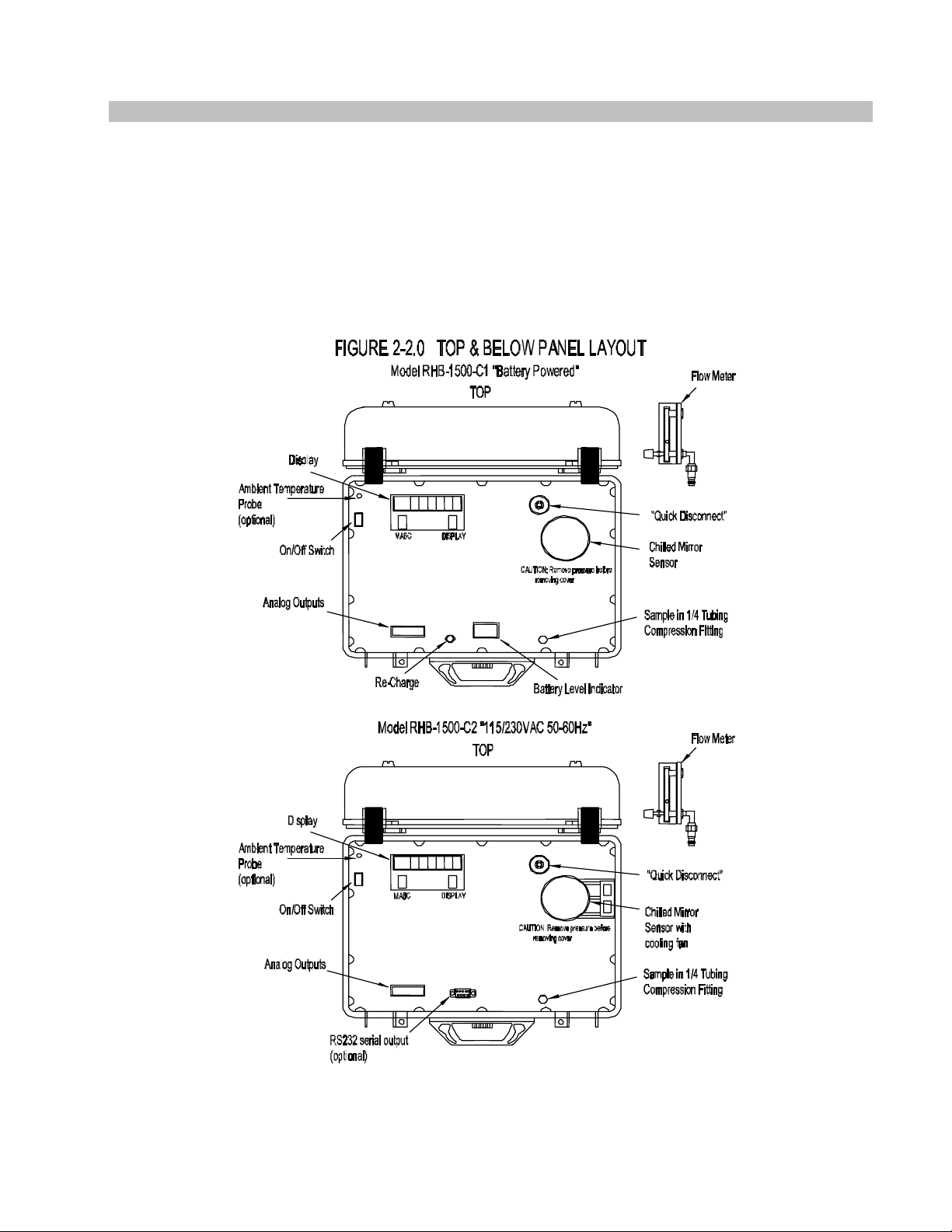
(Figure 2.2).
NOTE: The maximum inlet pressure is 150 PSIG.
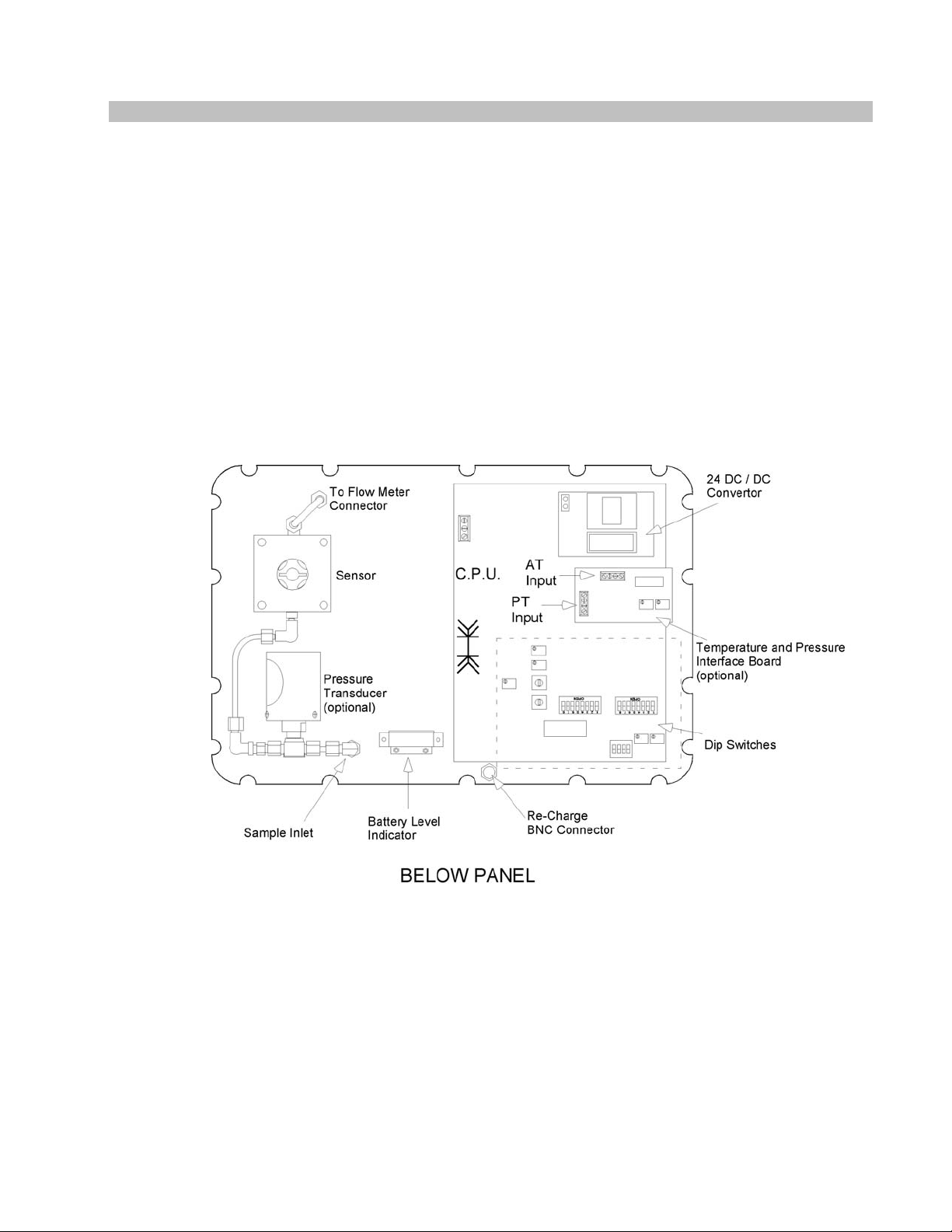
Figure 2-2.0 Drawing Model RHB-1500-C1 & Model RHB-1500-C2
Figure 2-2.1 Drawing Model RHB-1500-C1-Sx “underneath”
Figure 2-2.2 Drawing Model RHB-1500-C1-DsX “Insertion Probe”
Model RHB-1500-C
2.2 ALARM RELAY CONNECTIONS
When the programmed Alarm Set Point conditions are met, the alarm relay will be energized.
Before connecting any device to the Alarm Relay contacts, check the
contact ratings in the Specifications section.
1. Connect one of the signal wires to the CA (Center Arm) and the other wire to either the NO
(Normally Open) or NC (Normally Closed) terminal. Which ever is preferred by the
installer.
(See Figure 2.3)
2.3 ANALOG OUTPUT CONNECTIONS
“4-20mA out”. All connections can be made at terminal strip. (See Figure 2.3)
1. Connect the high signal wire to the “+” terminal and the low side to the “-“ terminal.
2.4 SERIAL PORT OUTPUT CONNECTIONS (Optional)
1. “RS232 out”. (See Figure 2.3)
4
Page 5
Model RHB-1500-C
Model RHB-1500-C
Portable Dew Point Monitor
Portable Dew Point Monitor
5
5
Page 6
Model RHB-1500-C
Portable Dew Point Monitor
FIGURE 2-2.1
WITH S-TYPE SENSOR
6
Page 7

Model RHB-1500-C
Portable Dew Point Monitor
7
Page 8

Model RHB-1500-C
Portable Dew Point Monitor
FIGURE 2-3 WIRING CONNECTORS
8
Page 9

Model RHB-1500-C
Portable Dew Point Monitor
3.0 FUNCTIONAL DESCRIPTION
The front panel of the Model RHB-1500-C Battery Powered DPM consists of an
LED Display and two push-buttons.
1.) MABC- Manual Automatic Balance Cycle
2.) DISPLAY “SCAN”- Allows viewing of all Parameters or selection of desired
measurement.
3.1 Display
The eight character alphanumeric LED display is used to display dew point data
and status messages.
Dew point data is displayed as “DP 34.8 F”, with the units in degrees C or F.
(See Set-Up section)
When a status message is necessary, the display will alternate between the data and
the message at about 2 second intervals.
The possible status messages and their meanings are:
• “ABC CYCL” : Indicates that an Automatic Balance Cycle is in progress.
During an ABC Cycle:
The mirror is heated above the ambient temperature for a period of 1 to 3
minutes as determined by the last measured dew point.
After sufficient time has elapsed to ensure that the mirror is dry, the reflected light
level of the mirror is measured and if necessary adjusted to the reference level.
After the adjustment is made the instrument will begin cooling and seeking the dew
point. When a stable lock on the dew point is achieved the “ABC CYCL” message
will disappear and normal operation will resume.
The analog output is held to the dew point value just before the cycle started until the
completion of the ABC cycle.
If an alarm condition is present when the ABC cycle begins, the audible alarm and the
ALARM display are disabled but the Alarm Relay remains energized.
• “ALARM”: The Alarm Set Point has been exceeded. The Alarm Relay will be energized.
• “CLN MIRR”: During an ABC Cycle, the condition of the sensor mirror and optics are
analyzed and a correction is made for changes in the reflectivity since the last cycle. If
the mirror reflectivity has decreased beyond the automatic correction range this
message will appear at the end of the ABC cycle and indicates that the sensor mirror
needs a manual cleaning. Perform the “Mirror Cleaning Procedure” in the
MAINTENANCE and CALIBRATION Section.
Note: The instrument may appear to operate normally with this message present,
but the data should not be relied upon, until the appropriate maintenance is
performed.
9
Page 10

Model RHB-1500-C
Portable Dew Point Monitor
3.0 FUNCTIONAL DESCRIPTION (CONTINUED)
• “CHK SNSR” : If during the ABC Cycle, the reflectivity has increased significantly due to
excessive drift of the optics, or abnormal circuit performance, this message will appear.
To determine the cause, take the following steps.
-Clean the mirror.
-Initiate an MABC Cycle.
-Check the sample system for proper flow.
-Check for loose connections or components on the printed circuit board and sensor.
If the condition cannot be resolved with these checks, contact Omega for service.
3.2 MABC Button
Pressing the MABC Button (Manual Automatic Balance Cycle) at any time will initiate an
ABC Cycle.
3.3 Clean Mirror Relay Output
The Clean Mirror Relay is a SPDT relay that is energized whenever maintenance to the
mirror is required.
During an ABC cycle, all alarm functions, including the relay, are disabled.
However, if an ABC Cycle is initiated when an alarm condition is present, the relay will
remain energized until the cycle is complete.
At the end of the cycle the relay will remain energized if the clean mirror condition is still
present or be de-energized if the alarm condition has passed.
3.4 Flow Control Valve
The sample flow rate is adjusted using this valve. Although the sample flow rate is not critical
for proper operation, the recommended rate is 1 – 2 SCFH (Standard Cubic Feet per Hour).
3.5 Alarm Relay Output
The Alarm Relay is a SPDT relay that is energized whenever the dew point exceeds the
Alarm Set Point.
During an ABC cycle, all alarm functions, including the relay, are disabled.
However, if an ABC Cycle is initiated when an alarm condition is present, the relay will
remain energized until the cycle is complete.
At the end of the cycle the relay will remain energized if the alarm condition is still present
or be de-energized if the alarm condition has passed.
3.6 Analog Output
The analog output is a 4 to 20mA output, proportional to the dew point, and scaled at the
factory for –58 to 122 °F (-50 to 50 °C).
During an ABC Cycle, the output is “held” at the dew point until the cycle is completed.
3.7 Display “SCAN” Button
Display feature allows the viewing of select parameter or scanning of all three
parameters at 3-second intervals.
10
Page 11

Model RHB-1500-C
Portable Dew Point Monitor
4.0 SETUP
4.1 Alarm Set Point (Figure 4.1)
The alarm set point temperature is set by DIP switch S2 as an integer. The switch setting
represents an eight bit binary number in degrees C with position 8 as the least significant bit
(LSB) and position 2 as the most significant bit (MSB). Position 1 is the sign bit.
An ‘open’ switch is a ‘1’ and ‘closed’ is a ‘0’.
If the desired set point is in degrees F, convert it to Celsius before proceeding.
Set the switches as follows:
1. Convert the desired set point temperature from degrees C to its eight bit binary equivalent
code. Table 4.1 is provided to convert F to C and the equivalent eight bit binary code.
2. Set S1-1 ‘closed’ and S1-2 ‘open’. The alarm temperature setting will be displayed in
degrees C.
NOTE: S1-1 determines whether C or F is displayed in both the measurement and
alarm set modes.
S1-2 will switch the display between the dew point and the Alarm Setting.
3. Set S2, positions 1 through 8 according to the eight bit binary number determined in
step 1. A ‘1’ is ‘open’, and a ‘0’ is ‘closed’.
4. The display should now read the set point temperature in degrees Celsius.
5. If Fahrenheit units are desired, set S1-1 to ‘open’.
6. Return to dew point display by setting S1-2 to ‘closed’.
11
Page 12

Model RHB-1500-C
Portable Dew Point Monitor
FIGURE 4-1
SETUP
12
Page 13

Model RHB-1500-C
Portable Dew Point Monitor
TABLE 4.1 SETUP
C F BINARY C F BINARY
-50.0 -58.0 10110010 0.0 32.0 00000000
-49.0 -56.0 10110001 1.0 33.0 00000001
-48.0 -54.0 10110000 2.0 35.0 00000010
-47.0 -52.0 10101111 3.0 37.0 00000011
-46.0 -50.0 10101110 4.0 39.0 00000100
-45.0 -49.0 10101101 5.0 41.0 00000101
-44.0 -47.0 10101100 6.0 42.0 00000110
-43.0 -45.0 10101011 7.0 44.0 00000111
-42.0 -43.0 10101010 8.0 46.0 00001000
-41.0 -41.0 10101001 9.0 48.0 00001001
-40.0 -40.0 10101000 10.0 50.0 00001010
-39.0 -38.0 10100111 11.0 51.0 00001011
-38.0 -36.0 10100110 12.0 53.0 00001100
-37.0 -34.0 10100101 13.0 55.0 00001101
-36.0 -32.0 10100100 14.0 57.0 00001110
-35.0 -31.0 10100011 15.0 59.0 00001111
-34.0 -29.0 10100010 16.0 60.0 00010000
-33.0 -27.0 10100001 17.0 62.0 00010001
-32.0 -25.0 10100000 18.0 64.0 00010010
-31.0 -23.0 10011111 19.0 66.0 00010011
-30.0 -22.0 10011110 20.0 68.0 00010100
-29.0 -20.0 10011101 21.0 69.0 00010101
-28.0 -18.0 10011100 22.0 71.0 00010110
-27.0 -16.0 10011011 23.0 73.0 00010111
-26.0 -14.0 10011010 24.0 75.0 00011000
-25.0 -13.0 10011001 25.0 77.0 00011001
-24.0 -11.0 10011000 26.0 78.0 00011010
-23.0 -9.0 10010111 27.0 80.0 00011011
-22.0 -7.0 10010110 28.0 82.0 00011100
-21.0 -5.0 10010101 29.0 84.0 00011101
-20.0 -4.0 10010100 30.0 86.0 00011110
-19.0 -2.0 10010011 31.0 87.0 00011111
-18.0 0.0 10010010 32.0 89.0 00100000
-17.0 1.0 10010001 33.0 91.0 00100001
-16.0 3.0 10010000 34.0 93.0 00100010
-15.0 5.0 10001111 35.0 95.0 00100011
-14.0 6.0 10001110 36.0 96.0 00100100
-13.0 8.0 10001101 37.0 98.0 00100101
-12.0 10.0 10001100 38.0 100.0 00100110
-11.0 12.0 10001011 39.0 102.0 00100111
-10.0 14.0 10001010 40.0 104.0 00101000
-9.0 15.0 10001001 41.0 105.0 00101001
-8.0 17.0 10001000 42.0 107.0 00101010
-7.0 19.0 10000111 43.0 109.0 00101011
-6.0 21.0 10000110 44.0 111.0 00101100
-5.0 23.0 10000101 45.0 113.0 00101101
-4.0 24.0 10000100 46.0 114.0 00101110
-3.0 26.0 10000011 47.0 116.0 00101111
-2.0 28.0 10000010 48.0 118.0 00110000
-1.0 30.0 10000001 49.0 120.0 00110001
0.0 32.0 00000000 50.0 122.0 00110010
13
Page 14

Model RHB-1500-C
Portable Dew Point Monitor
4.2 ABC Interval
The ABC Interval is the time between the automatic initiation of ABC Cycles. In typical
applications, an interval of 24 hours is recommended and set at the factory. However,
in cases where ambient conditions are more variable, or the sample gas is higher in
contaminants, a shorter interval may be required.
The times listed below are approximate.
The interval is adjustable in 4 hour increments from 4 to 28 hours.
Switch positions S1-6, -7, and -8 represent a three bit binary code with a weight of
4 hrs. per unit.
To set the interval, set S1-6, S1-7, and S1-8 according to the binary number from
Table 4.2 below. The factory default is 24 hrs.
NOTE: ‘CLOSED’ is a zero and ‘OPEN’ is a one.
ABC
INTERVAL
OFF
4 hrs. 0 0 1
8 hrs. 0 1 0
12 hrs. 0 1 1
16 hrs. 1 0 0
20 hrs. 1 0 1
24 hrs. 1 1 0
28 hrs. 1 1 1
Table 4.2 converts the required interval in hours to a three bit binary number.
S1- 6 S1- 7 S1- 8
0 0 0
14
Page 15

Model RHB-1500-C
Portable Dew Point Monitor
5.0 MAINTENANCE
5.1 ROUTINE MAINTENANCE
To ensure the maximum in accurate and reliable operation of any optical chilled mirror
system, a periodic maintenance program should be established.
5.2 MIRROR CLEANING SCHEDULE
Over time particulates and other matter present in the sample gas and not captured by filters
build up on the mirror. The result of the buildup of contaminants on the mirror surface is
reduced dry mirror reflectivity and a change in the optical reference point. The ABC Cycle will
automatically readjust the optics to the reference point periodically, but eventually the
adjustment range will be exceeded and a manual cleaning of the mirror may be necessary.
When the contamination becomes too much to be adjusted automatically an error will be
displayed at the end of the ABC Cycle.
Normally, intervals of 90 days between routine mirror cleanings can be easily achieved.
However, if the sample gas contaminants are particularly high, more frequent mirror
cleanings may be required.
5.3 MIRROR CLEANING PROCEDURE (Figure 5.1)
When mirror cleaning is required as a periodic maintenance item or the “CLN MIRR” or “CHK
SNSR” message appears on the display, proceed as follows.
1. Turn power off.
CAUTION !
When operating with a pressurized sampling system, be sure to remove pressure from
the Sensor prior to removing the Sensor cover.
2. Remove the spin-off cover from the Sensor to expose the mirror.
3. Moisten a clean cotton swab with isopropyl alcohol. Cotton swabs and cleaning bottle
are provided in the Cleaning Kit supplied with the system.
4. Wipe the mirror surface and the optics surface in a circular motion.
5. After cleaning the mirror surface, wipe the surfaces dry with a clean Q-tip.
6. Next, moisten a clean Q-tip with clean, preferably distilled water and wipe the
mirror and optics areas.
7. Dry these areas thoroughly with a clean, dry Q-tip.
8. Replace the sensor cover.
9. Re-establish sample pressure and flow.
10. Turn power on.
15
Page 16

Model RHB-1500-C
Portable Dew Point Monitor
FIGURE 5.1 S2 WITH COVER REMOVED FOR MIRROR CLEANING
16
Page 17

Model RHB-1500-C
Portable Dew Point Monitor
6.0 SPECIFICATIONS
Measurement Range
-Dew/ Frost Point -50 to 50°C ( S2 sensor)
-75 to 75°C ( S3 sensor)
-Pressure Transducer 0-150 p.s.i.g. (gauge)
-Ambient Temperature Probe -50°C to 50°C
-58°F to 122°F
Measurement Accuracy
-Dew/ Frost Point ±0.25°C (0.45°F) Entire Range
-Pressure Transducer ±0.5% (Full Scale)
-Ambient Temperature Probe ±0.2°C (0.36°F) Entire Range
Functional
Power/ Charger: 115VAC/60Hz, or 230VAC/50Hz; 40 watts
(Max)
Operating Temperature:
Control Unit/Sensor
S-Type 32 to 122°F (0 to 50°C)
D-Type 32 to 185°F (0 to 85°C)
Sample Connection: ¼ female compression tubing fitting
Sample Flow: 0.5 to 5scfh, Integral flow meter
Sample Pressure: 0 to 150psig max
Analog Output: 4 to 20mA, Scaled
Range: Selectable (See available sensor ranges)
Compliance: 9.0 VDC, 450 ohms
Display: Eight Digit Alphanumeric LED, 0.5” High.
High dew point Alarm:
- Visual Flashing Message on Display
- Relay Contacts 2 Form C, non-latching,
10A @ 240VAC
8A @ 24 VDC
½ HP @ 240VAC
Physical
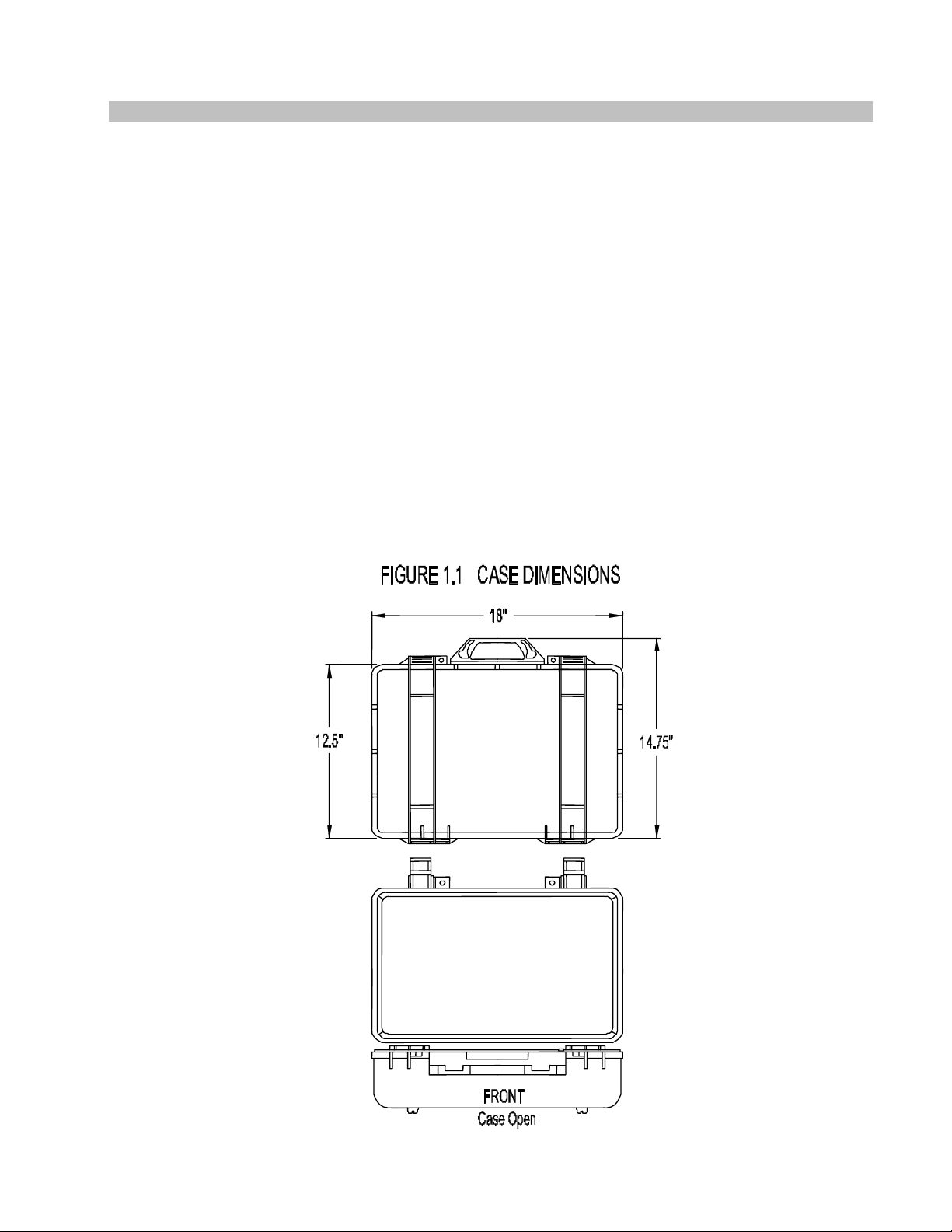
Dimensions: 14.75”H x 18”L x 7”W
Weight: C1 (24 lbs.) C2 (14 lbs.)
Standard Features Optional Features
- Microprocessor Controlled. - Pressure transducer; required for PPMv
- 8 Digit Alphanumeric LED Display. - Rotary Vane Vacuum Pump
- Automatic Balance Control.(ABC) - Ambient Temperature; required for %RH
- User settable high alarm limit. - RS232 Serial Port
- Alarm Relay, Form C. - Probe Style Sensor
- Analog Output, 4 – 20 ma.
- Integral flow meter.
- Visual alarms
- Battery Level Indicator & Charger
17
Page 18

Model RHB-1500-C
Portable Dew Point Monitor
18
Page 19

Model RHB-1500-C
Portable Dew Point Monitor
19
Page 20

Model RHB-1500-C
Portable Dew Point Monitor
Where Do I Find Everything I Need for
Process Measurement and Control?
OMEGA...Of Course!
Shop online at omega.com
TEMPERATURE
Thermocouple, RTD & Thermistor Probes, Connectors, Panels &
Assemblies
Wire: Thermocouple, RTD & Thermistor
Calibrators & Ice Point References
Recorders, Controllers & Process Monitors
Infrared Pyrometers
PRESSURE, STRAIN AND FORCE
Transducers & Strain Gages
Load Cells & Pressure Gages
Displacement Transducers
Instrumentation & Accessories
FLOW / LEVEL
Air Velocity Indicators
Turbine / Paddlewheel Systems
Totalizers & Batch Controllers
pH / CONDUCTIVITY
Benchtop / Laboratory Meters
Controllers, Calibrators, Simulators & Pumps
Industrial pH & Conductivity Equipment
DATA ACQUISITION
Communications-Based Acquisition Systems
Plug-in Cards for Apple, IBM & Compatibles
Datalogging Systems
Recorders, Printers & Plotters
HEATERS
Cartridge & Strip Heaters
Immersion & Band Heaters
Flexible Heaters
Laboratory Heaters
ENVIRONMENTAL
MONITORING AND CONTROL
Refractometers
Pumps & Tubing
Air, Soil & Water Monitors
Industrial Water & Wastewater Treatment
pH, Conductivity & Dissolved Oxygen Instruments
Rotameters, Gas Mass Flowmeters & Flow Computers
pH Electrodes, Testers & Accessories
Data Acquisition & Engineering Software
Heating Cable
Metering & Control Instrumentation
20
 Loading...