

Page 1
www.omega.com
e-mail: info@omega.com
omega.com
®
®
User’s Guide
RH70 and RH70-AC
Handheld T emperature/
Humidity/Dew Point
Indicators
DE
Shop online at
TEM%R° MA
W
MODE MODE MODE
STORAGE
SAVE
DUM
HYGRO-THERMOMETER
° MI
DIGITAL
MEMORY
MADE
IN
USA
O
OF
Page 2

Servicing North America:
USA: One Omega Drive, Box 4047
ISO 9001 Certified Stamford CT 06907-0047
Tel: (203) 359-1660 FAX: (203) 359-7700
e-mail: info@omega.com
Canada: 976 Bergar
Laval (Quebec) H7L 5A1
Tel: (514) 856-6928 FAX: (514) 856-6886
e-mail: info@omega.ca
For immediate technical or application assistance:
USA and Canada: Sales Service: 1-800-826-6342 / 1-800-TC-OMEGA
®
Customer Service: 1-800-622-2378 / 1-800-622-BEST
®
Engineering Service: 1-800-872-9436 / 1-800-USA-WHEN
®
TELEX: 996404 EASYLINK: 62968934 CABLE: OMEGA
Mexico: En Espan˜ol: (001) 203-359-7803 e-mail: espanol@omega.com
FAX: ( 001) 203-359-7807 info@omega.com.mx
Servicing Europe:
Benelux: Postbus 8034, 1180 LA Amstelveen, The Netherlands
Tel: +31 (0)20 3472121 FAX: +31 (0)20 6434643
Toll Free in Benelux: 0800 0993344
e-mail: nl@omega.com
Czech Republic: Rudé armády 1868, 733 01 Karviná 8
Tel: +420 (0)69 6311899 FAX: +420 (0)69 6311114
Toll Free: 0800-1-66342 e-mail: czech@omega.com
France: 9, rue Denis Papin, 78190 Trappes
Tel: +33 (0)130 621 400 FAX: +33 (0)130 699 120
Toll Free in France: 0800-4-06342
e-mail: france@omega.com
Germany/Austria: Daimlerstrasse 26, D-75392 Deckenpfronn, Germany
Tel: +49 (0)7056 9398-0 FAX: +49 (0)7056 9398-29
Toll Free in Germany: 0800 639 7678
e-mail: germany@omega.com
United Kingdom: One Omega Drive, River Bend Technology Centre
ISO 9002 Certified Northbank, Irlam, Manchester
M44 5BD United Kingdom
Tel: +44 (0)161 777 6611 FAX: +44 (0)161 777 6622
Toll Free in United Kingdom: 0800-488-488
e-mail: sales@omega.co.uk
omega.comomega.com
OMEGAnet®Online Service Internet e-mail
www.omega.com info@omega.com
It is the policy of OMEGA to comply with all worldwide safety and EMC/EMI regulations that
apply. OMEGA is constantly pursuing certification of its products to the European New Approach
Directives. OMEGA will add the CE mark to every appropriate device upon certification.
The information contained in this document is believed to be correct, but OMEGA Engineering, Inc. accepts
no liability for any errors it contains, and reserves the right to alter specifications without notice.
WARNING: These products are not designed for use in, and should not be used for, patient-connected applications.
®
®
Page 3

WARRANTY/DISCLAIMER
OMEGA ENGINEERING, INC. warrants this unit to be free of defects in materials and
workmanship for a period of 13 months from date of purchase. OMEGA’s Warranty
adds an additional one (1) month grace period to the normal one (1) year product
warranty to cover handling and shipping time. This ensures that OMEGA’s
customers receive maximum coverage on each product.
If the unit malfunctions, it must be returned to the factory for evaluation. OMEGA’s
Customer Service Department will issue an Authorized Return (AR) number immediately upon phone or written request. Upon examination by OMEGA, if the unit is found to
be defective, it will be repaired or replaced at no charge. OMEGA’s WARRANTY does
not apply to defects resulting from any action of the purchaser, including but not limited to mishandling, improper interfacing, operation outside of design limits, improper
repair, or unauthorized modification. This WARRANTY is VOID if the unit shows evidence of having been tampered with or shows evidence of having been damaged as a
result of excessive corrosion; or current, heat, moisture or vibration; improper specification; misapplication; misuse or other operating conditions outside of OMEGA’s control. Components which wear are not warranted, including but not limited to contact
points, fuses, and triacs.
OMEGA is pleased to offer suggestions on the use of its various products.
However, OMEGA neither assumes responsibility for any omissions or errors nor
assumes liability for any damages that result from the use of its products in
accordance with information provided by OMEGA, either verbal or written.
OMEGA warrants only that the parts manufactured by it will be as specified and
free of defects. OMEGA MAKES NO OTHER WARRANTIES OR REPRESENTATIONS OF ANY KIND WHATSOEVER, EXPRESS OR IMPLIED, EXCEPT THAT OF
TITLE, AND ALL IMPLIED WARRANTIES INCLUDING ANY WARRANTY OF MERCHANTABILITY AND FITNESS FOR A PARTICULAR PURPOSE ARE HEREBY DISCLAIMED. LIMITATION OF LIABILITY: The remedies of purchaser set forth herein
are exclusive, and the total liability of OMEGA with respect to this order, whether
based on contract, warranty, negligence, indemnification, strict liability or otherwise, shall not exceed the purchase price of the component upon which liability
is based. In no event shall OMEGA be liable for consequential, incidental or special damages.
CONDITIONS: Equipment sold by OMEGA is not intended to be used, nor shall it be
used: (1) as a “Basic Component” under 10 CFR 21 (NRC), used in or with any nuclear
installation or activity; or (2) in medical applications or used on humans. Should any
Product(s) be used in or with any nuclear installation or activity, medical application,
used on humans, or misused in any way, OMEGA assumes no responsibility as set
forth in our basic WARRANTY/DISCLAIMER language, and, additionally, purchaser will
indemnify OMEGA and hold OMEGA harmless from any liability or damage
whatsoever arising out of the use of the Product(s) in such a manner.
RETURN REQUESTS/INQUIRIES
Direct all warranty and repair requests/inquiries to the OMEGA Customer Service
Department. BEFORE RETURNING ANY PRODUCT(S) TO OMEGA, PURCHASER
MUST OBTAIN AN AUTHORIZED RETURN (AR) NUMBER FROM OMEGA’S
CUSTOMER SERVICE DEPARTMENT (IN ORDER TO AVOID PROCESSING DELAYS).
The assigned AR number should then be marked on the outside of the return package
and on any correspondence.
The purchaser is responsible for shipping charges, freight, insurance and proper
packaging to prevent breakage in transit.
FOR WARRANTY
RETURNS, please have
the following information available
BEFORE contacting OMEGA:
1. Purchase Order number under which
the product was PURCHASED,
2. Model and serial number of the product
under warranty, and
3. Repair instructions and/or specific
problems relative to the product.
FOR NON-WARRANTY REPAIRS,
consult
OMEGA for current repair charges. Have
the following information available
BEFORE contacting OMEGA:
1. Purchase Order number to cover the
COST of the repair,
2. Model and serial number of the product,
and
3. Repair instructions and/or specific
problems relative to the product.
OMEGA’s policy is to make running changes, not model changes, whenever an improvement is possible.
This affords our customers the latest in technology and engineering.
OMEGA is a registered trademark of OMEGA ENGINEERING, INC.
© Copyright 2001 OMEGA ENGINEERING, INC. All rights reserved. This document may not be copied,
photocopied, reproduced, translated, or reduced to any electronic medium or machine-readable form, in
whole or in part, without the prior written consent of OMEGA ENGINEERING, INC.
UUSASA
MADE
ININ
Page 4

NOTES
26
Page 5
i
Page 6

ii
Page 7

NOTES
25
Page 8

NOTES
24
Page 9

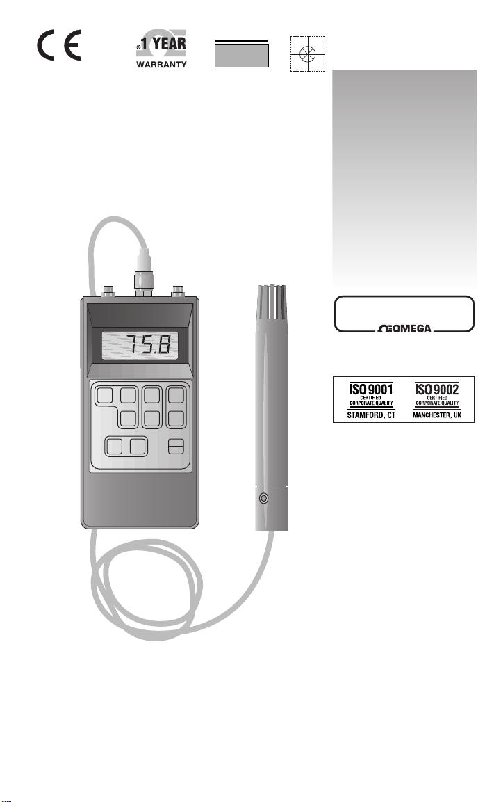
SECTION 1 INTRODUCTION
The OMEGA® RH70 Handheld Temperature /Humidity /
Dew Point Indicator is a microprocessor-based digital
hygrometer / thermometer with built-in date storage and an
RS-232-C interface. The RH70-Ac can be operated using a
rechargeable Ni-Cad battery.
The RH70/RH70-AC Indicator is used for measuring
humidity and temperature in heating, ventilation and air
conditioning industries. The RH70)/RH70-AC calculates the
dew point and displays in either °C or °F. The RH70/RH70-AC
features 2% reading accuracy for humidity and 0.2%
reading accuracy for temperature. From the front
keyboard, the user can select English or Metric Units,
operating mode and data storage controls.
This handheld indicator can store up to 999 lines of data.
Each single line of data contains one temperature and one
relative humidity reading. The dew point reading can not
be saved or transformed (it can only be read on the
display).
Figure 1.1 shows the RH70 Indicator.
Figure 1.1 RH70 Temperature/Humidity/Dew Point Indicator
1
Page 10

Two different models of the RH70 are available from
OMEGA Engineering
PART
NUMBER
DESCRIPTION
RH70
RH70-AC
PORTABLE HYGROMETER/
THERMOMETER WITH 9V
BATTERY
RH70 WITH RECHARGEABLE
BATTERY AND CHARGER
For accessories, refer to Section 10.
SECTION 2 UNPACKING
Remove the Packing list and verify that all equipment has been
received. If there are any questions about the shipment, please
call OMEGA Customer Service Department.
Upon receipt of shipment, inspect the container and equipment
for any signs of damage. Take particular note of any evidence of
rough handling in transit. Immediately report any damage to the
shipping agent.
NOTE
The carrier will not honor any claims
unless all shipping material is saved for
their examination. After examining and
removing contents, save packing material
and carton in the event reshipment is
necessary.
2
Page 11

23
SPECIFICATIONS ( Cont’d)
TEMPERATURE
RANGE: -5 TO 175°F (-20 to 80°C)
ACCURACY: 0.2% reading ± 1 digit
RESOLUTION: 0.7°F (0.4°C)
SENSING ELEMENT: 100 ohms Pt RTD sensor
RESPONSE TIME: 60 seconds
SEPARATE RTD PROBE
RANGE: -148 to 572°F (-10 to 300°C)
ACCURACY: 0.2% of reading ±1 digit
OPERATING TEMPERATURE
INSTRUMENT: 32 to 125°F (0 to 50°C)
RH/ TEMP PROBE: -5 to 175°F (-20 to 80°C)
WITH SEPARATE RTD PROBE: -148 to 572°F (-100 to 300°C)
POWER SUPPLY
RH70: One 9V battery
RH70-AC: One 9V Ni-Cad battery with
AC charger
BATTERY LIFE
9V ALKALINE: 78 hours
Ni-CAD RECHARGEABLE: 15 hours
(FULLY CHARGED)
GENERAL
BAUD RATE: 1200 Baud
DISPLAY: 1/2” LCD, 4 digit
ANALOG OUTPUTS
RELATIVE HUMIDITY: 0 to 2 volts
TEMPERATURE: 0 to 2 volts
DIGITAL OUTPUT: standard RS-232-C
DATA STORAGE: Store up to 999
measurements for both
humidity and temperature.
DIMENSIONS
INSTRUMENT: 5.9” H x 3.15” W x 1.2” D
PROBE: 6” L x 0.93 diameter
PROBE CABLE: 5 feet
WEIGHT
INSTRUMENT: 9.49 oz (269 gm)
PROBE AND CABLE: 2.75 oz (78 gm)
Page 12

22
9.2 REACHING SATURATION LEVELS
The measuring range for Relative Humidity is from 5% to 95%.
The characteristics are not altered when operating in conditions
close to saturation; however, exposure to high humidities and
the moistening risk of the humidity sensor can momentarily falsify
the measurements. For example, a permanent measurement for
an extended duration measurement (>1/2 hour) at higher than
90% RH leads to a phenomena of secondary absorption.
This results in an evolution able to reach approximately +6% of
a %RH measurement close to saturation. The evolution is memorized
by the humidity sensor and it can take up to 24 hours of drying
to return the sensor to its original
characteristics.
SECTION 10 ACCESSORIES
SECTION 11 SPECIFICATIONS
TEMPERATURE
RANGE: 5 to 95%RH
ACCURACY: 2%RH ± 1 digit
RESOLUTION: 0.1%RH
TEMP DRIFT: ±0.5% RH per 10°C
RESPONSE TIME: Up to 90% of fluctuations in 10 s
SENSING ELEMENT: Thin film capacitive type sensor
DEW POINT
RANGE: -5 to 175°F (-20 to 80°C)
SENSING ELEMENT: Mathematically calculated
from RH and temperature
readings (using a look-up table)
PART NUMBER DESCRIPTION
RH70-RP Replacement Humidity/
temperature probe with
5 ft cable
RH70-SF Sinter Filter Cap
Page 13

Please note that the following items should be in a box:
MODEL RH70
QTY DESCRIPTION QTY DESCRIPTION
MODEL RH70-AC
1 RH70 Indicator
1 Humidity/ Temperature Probe
with 5 ft cable
1 RS-232 Cable (5 ft)
1 Analog Output Cable (5 ft)
1 9V Battery
1 Rugged Carrying Case
1 Operator’s Manual
1 RH70-AC Indicator
1 Humidity/ Temperature Probe
with 5 ft cable
1 RS-232 Cable (5 ft)
1 Analog Output Cable (5 ft)
1 9V Rechargeable Ni-Cad
Battery
1 Rugged Carrying Case
1 Operator’s Manual
SECTION 3 DISPLAY AND KEYPADS OPERATION
Figure 3-1. RH70/RH70-AC
3
Page 14

ITEM KEY DESCRIPTION(refer to Figure 3
1 -- Connector for the RS-232 Cable
2 -- Connector for the Humidity/Temperature Probe
3 -- Connector for the Analog Output Cable (0-2V)
4 -- Instrument LCD Display (4 Digits)
5 °F Pressing the “°F” key displays a temperature
reading in degrees Fahrenheit. The reading is
updated 2.5 times per second.
6 °C Pressing the “°C” key displays a temperature
reading in degrees Celsius. The reading is
updated 2.5 times per second.
7 MAX Pressing the “MAX” key displays the highest value
in either Temperature or Relative Humidity. This
feature is not applicable to the Dew Point values.
The maximum value (since turning on the RH70)
alternates with the flashing”H”. To exit from the
MIN/MAX mode, and continue to monitor
temperature, press the “TEMP” key. To exit from
the MIN/MAX mode and continue to monitor
humidity, press the “%RH” key.
8 MIN Pressing the “MIN” key displays the highest value
in either Temperature or Relative Humidity. This
feature is not applicable to the Dew Point values.
The maximum value (since turning on the RH70)
alternates with the flashing”L”. To exit from the
MIN/MAX mode, and continue to monitor
temperature, press the “TEMP” key. To exit from
the MIN/MAX mode and continue to monitor
humidity, press the “%RH” key.
9 The RH70 is turned ON by pressing the“ON/OFF”
key. Pressing it again turns the RH70 off.
10 SAVE Pressing the “SAVE” key stores the current temperature
and relative humidity readings at the instant the
key is pressed, i.e. 98.0°F and 33.2% RH. Dew Point
values are NOT saved. See NOTES on next page
ON
OFF
4
Page 15

21
PROBLEM CONDITION SOLUTION
“E-04” on display No communication Check RS-232
through the RS-232 connection and
data link with a peripherals
“E-06” on display Relative Humidity
lower than measuring ----
“E-07” on display Relative Humidity
higher than measuring ----
“E-08” on display Temperature lower
“E-09” on display Temperature higher
than measuring range. Connect probe
“E-10” on display Relative Humidity not
within range for ----
calculating the Dew
Point (3.0% to 97.0% RH)
“E-11” on display Temperature not within
range for calculating the ---Dew Point (-5 to 175°F
or -20 to 80*C)
“E-XX” on display Error code for 50 or Contact OMEGA
higher (shows internal
errors)
“E-51” on display Some hardware has Contact OMEGA
come loose internally.
Page 16

20
PROBLEM CONDITION SOLUTION
“L” on display Weak battery Replace battery
(less than 6V) (refer to Section
8.1 on how to
replace battery)
“E-02” on display Instrument has Clear memory
reached max. using “DUMP”
key (See Section
allowable number 5.3.3).
of stored data
points (at 999).
“E-03” on display Storage memory Press “SAVE”
is empty key to store
measurements.
SECTION 8 POWER SOURCE INFORMATION
8.1 BATTERY REPLACEMENT
To replace the battery, gently open the battery cover on the
back of the unit (use a small screwdriver, if necessary). Plug
in the 9V battery observing polarity, place in compartment
and gently close the cover.
8.2 RH70-AC POWER INFORMATION
Check to see that a Ni-Cad battery is in the RH70-AC. Plug
in one side of the AC Charging Adapter into the socket on
the side of the RH70-AC and the other end to a 110VAC
outlet.
The RH70-AC will NOT work with the AC charging adapter
alone. The rechargeable Ni-Cad battery must be installed in
order to operate the unit.
Page 17

ITEM KEY DESCRIPTION(refer to Figure 3
The stored values are retained,
even when the unit is turned
off.
Pressing the “SAVE” key while
viewing a temperature reading
automatically saves the corresponding
humidity reading at that moment and
vice versa.
11 DUMP Pressing the “DUMP” key down-loads the
stored measurements to a connected printer or
computer (IBM XT, AT, or compatible) through
the RS-232 cable.
TO CLEAR STORED DATA: Data is maintained
in the RH70 memory for a minimum of 1 year or until
it is cleared. Clearing the memory is done by pressing
and holding down the “DUMP” key while turning ON
the RH70.
12 %RH Pressing the “5RH” key displays the humidity reading in
% Relative Humidity (5 to 95% RH). The reading is updated
2.5 times per second. Refer to Section 9.2, Reaching
Saturation, if the sensor becomes saturated.
Notice that the RH reading is left
always displayed by the LEFT
most digits of the meter display.
13 Pressing the “DEW PNT” key displays a calculated Dew
Point reading. The user can toggle the Dew Point value
between °F and °C. Pressing the “DEW PNT” key and
then the “°F” key will display the Dew Point in degrees
Fahrenheit. Pressing the “DEW PNT” key and then the
“°C” key will display the Dew Point in degrees Celsius.
14 TEMP Pressing the “TEMP” key displays the temperature. When
the RH70 is first turned on, it defaults to degrees Fahrenheit.
Press “°F or °C” to select the desired units for displaying
temperature.
DEW
PNT
5
NOTE
NOTE
Page 18

6
SECTION 4 ASSEMBLY
4.1 PROBE ASSEMBLY
Connect the Humidity/Temperature Probe to the middle
connector on top of the RH70. Refer to item #2 in Figure 3-1
for the location of the probe connector. The male connector
on the cable and the female connector on the instrument are
keyed, so make sure they are lined up before connecting to
each other. Tighten knurled threaded fitting to secure the
cable to the instrument.
4.2 BATTERY ASSEMBLY
Gently open the battery cover on the back of the unit (use a small
screwdriver, if necessary). Plug in the 9V battery observing
polarity, place in compartment and gently close the cover.
4.3 AC CHARGING ADAPTER (RH70-AC ONLY)
1. Install the rechargeable Ni-Cad battery as described in
Section 4.2
2. Plug in one side of the AC Charging Adapter into the socket
on the side of the RH70-AC and the other end to a 110VAC
wall socket. Refer to 3-1 for the location of the socket on the
meter.
NOTE
The RH70-AC will NOT work
with the AC charging adapter
alone. The rechargeable Ni-Cad
battery must be installed in
order to operate the unit
WARNING
DO NOT OPERATE THE RH70-AC
WITH A NON-RECHARGEABLE
BATTERY AND THE AC CHARGING
ADAPTER TOGETHER. USE OF A
NONRECHARGEABLE BATTERY AND
THE RECHARGER CAN CAUSE THE
BATTERY TO EXPLODE!!
Page 19

19
2. Carefully fit the probe tip in the closed glass container with
the solution simulating 11% relative humidity. Make sure the
assembly is sealed. Let it sit for approximately one (1) hour.
Adjust the pot P4 until the display reads 11.0. Refer to Section 7.2
3. Repeat step 2 with the sodium chloride solution.
Carefully fit the probe tip in the closed container with the
solution simulating 76% RH for approximately one (1) hour.
Adjust P3 until the display reads 76.0.
4. Repeat steps 2 and 3 until 11% and 76% relative humidity
can be achieved without resetting pots P3 or P4.
5. Different relative humidities can be simulated by using any
of the following saturated solutions.
TEMPERATURE VS RELATIVE HUMIDITY
Ammonium Sulfate
Sodium Chloride
Ammonium Nitrate
Potassium Carbonate
Potassium Acetate
Lithium Chloride
81
76
65
44
22
11
80
75
62
43
22
11
SALT
SOLUTION
% RH AT
68°F (20°C)
% RH AT
77°F (25°C)
7.4 TEMPERATURE CALIBRATION
Temperature is measured using a precision RTD sensor
which is very stable by nature. The sensor electronics
generally do not go out of calibration.
Periodic checks can be performed to determine the
equipment accuracy in the temperature range. This is done
by comparing the RH70 readings to known temperature
values.
In the event that the RH70 is out of specification, contact
OMEGA. Temperature calibration can not be performed by
the user. Due to the complexity of the procedure, it is
required that the RH70 be returned to OMEGA Engineering
for recalibration. Do not attempt to recalibrate the RH70
yourself.
Page 20

18
7.3 HUMIDITY CALIBRATION
All calibrations should be made at room temperature (68°F to
77°F (20°C to 25°C)). Refer to Figure 7-1 for the location of the
calibration potentiometers (pots).
1. Connect the probe and the battery as described i
1. Carefully remove the sensor cap from the probe handle.
This is done by grasping the sensor cap and the lower
end of the probe enclosure firmly. Carefully twist in
opposite directions of each other and pull. Do not bend
the assembly since you could damage it. Be careful not to touch
the sensors.
Page 21

7
SECTION 5 OPERATING INSTRUCTIONS
5.1 PRINCIPLES OF OPERATION
RELATIVE HUMIDITY (%RH): This relates to the ratio of
actual water vapor pressure in the air to the vapor pressure
in saturated air at the same temperature. This unit measures
from 5% to 95%. Refer to Section 8 if saturation occurs.
Typical applications: monitoring computer rooms,
test chambers, pharmaceutical and food packaging places.
DEW POINT/FROST POINT: The dew point is the temperature
at which water vapor begins to condense. If the dew point
occurs below 32°F, it is called the frost point. Typical
applications: Heat treating, annealing atmospheres, dryer
control, instrument air monitoring, meteorological/environmental
measurements, and external paintwork.
5.2 MEASUREMENT PROCEDURES
1. Connect the probe and the battery as described in Section 4.
2. Turn on the RH70-AC by pressing the “ON/OFF” key. The
unit will display for two seconds each of the following.
“88.8.8” (this is an internal test) then,
the battery voltage, then “P” followed by three numbers
where the 3-digit number indicates how many data points
have been “saved” in the memory, +1. For example, when
3 readings are stored in memory, the display will show
“P004”. These three stored values are retained in memory,
even after shut-off.
NOTE
The RH70-AC is fully
operational while the NiCad battery is recharging.
After 0ne (1) hour the bat-
Refer to Section 3 for complete
operating details of each key on
NOTE
Page 22

3. Now you must instruct the RH70 what measurement to
display.
For TEMPERATURE: Press the “TEMP” key.
Pressing the “°F” or “°C” key will cause the display
to show the Temperature in the desired units.
For %RH: Press the %RH key.
For DEW POINT: Press the “DEW PNT” key.
Pressing the “°F” or “°C” key will cause the display
to show the Dew Point in the desired units.
4. Press the “ON/OFF” key to turn off the RH70.
5.3 SAVE/DUMP/CLEAR MEMORY
5.3.1 The Save Feature
Pressing the “SAVE” key will store BOTH the humidity AND the
temperature values the moment the key is pressed. The two are
simultaneously saved as one line of data. This means that pressing
the “SAVE” key while viewing the temperature reading automatically
saves the corresponding humidity reading AT THE SAME INSTANT.
Notice that when the “SAVE” key is pressed, the display will flash the
letter “P” followed by a 3-digit number (i.e. P204). This number indicates
how many data points have been saved in the memory, plus 1.
For example, when the FIRST data point is saved, “P002” will flash on
the display. This indicates that the RH70 has saved the reading and the
memory is ready and pointing to the next available address. However,
when the saved data is later down-loaded through the RS-232
connector, that first point will be labeled as “P001”. All the rest of the
points will follow in sequence. Refer to Section 5.5, “Sample RS-232
Data Format”.
Data is maintained in the RH70 memory for a minimum of 1 year or
until it is cleared. Refer to Memory section below for instructions to
clear the memory. A maximum of 999 temperature/humidity readings
can be saved.
Note that the Dew Point reading CAN NOT be saved or output to a
computer. The Dew Point can only be read on the display.
8
Page 23

17
It is important that the solutions must remain saturated for
those relative humidities to be valid. Increases in ambient
temperature will require agitation of the solution to ensure
saturated conditions. To prevent this from becoming a problem,
the solutions, once prepared, should be kept in a
temperature-controlled room.
7.2 PREPARING A SALT REFERENCE
To calibrate the humidity portion of the RH70, it is necessary
for the user to prepare two saturated salt solutions - one to
simulate 11% RH and one to simulate 76% RH (at 68°F).
Equipment Needed:
1. 2 glass containers (fitted to probe end without endcap)
and lid with a good seal.
2. Distilled water
3. Lithium Chloride (LiCl) (for 11% RH) and
4. Sodium Chloride (NaCl) (for 76% RH).
To simulate 11% RH, fill the bottom of two glass containers
approximately 1/4 full of distilled water. Add lithium chloride
until the solution is saturated (solution is saturated when an
additional crystal of solute which is added to the solution does
not enter into the solution). Keep the chamber closed for at least
one hour, with the temperature of the solution constant to prevent
the concentration of the salt solution form changing ( 68°F or 20°C).
To simulate 76% RH, follow the same procedure as above.
But in this case, in the second glass container, add sodium
chloride to the distilled water (until saturated). Let the solution
sit for at least one hour.
Page 24

16
6.3 HUMIDITY SENSOR HANDLING
Due to its design, and the ease of access, the humidity sensor
must be handles with care. AVOID ANY CONTACT with
fingers or with products which could be harmful to the good
permeability of the electrode and dielectric. The sensor must
not come in contact with dirt or other foreign material.
Incorrect readings can be caused by build-up of material,
which can increase or decrease the RH reading.
6.4 HUMIDITY SENSOR CLEANING
Use no solvents stronger than DISTILLED WATER to clean
the humidity sensor. If necessary, rinse the sensor with
distilled water, being careful not to touch it with your fingers.
After rinsing, the sensor should air dry for at least 24 hours
(preferably over an air flow register).
SECTION 7 CALIBRATION
The RH70 is calibrated at the factory.
The warranty is void if the label on the
probe handle is tampered with. Contact
OMEGA Engineering for service information
The following procedures are necessary
only if the unit is operating out of
specification and is no longer under
warranty. These procedures should be
performed by a qualified technician.
7.1 SALT REFERENCES
When a closed air space is maintained in equilibrium with a
saturated aqueous salt solution, the relative humidity of the
enclosed air remains constant as long as the temperature and
pressure do not change.
NOTE
WARNING
DO NOT EXPOSE THE RH70 HUMIDITY SENSOR
TO TEMPERATURES OVER 175°F (80°C) !
DOING SO , WILL DESTROY THE SENSOR.
Page 25

9
There is no internal clock in the RH70 or RH70-AC for record
keeping purposes. It is up to you to keep track of the time
when the readings are saved.
5.3.2 The Dump Feature
Pressing the “DUMP” key will down-load (or dump) the
measurements stored to a connected serial printer or computer
(IBM XT, AT, or compatible). These points are still retained in
memory, however, even after being dumped through the
RS-232 connector. Refer to Section 5.5 for complete details on
the RS-232 feature, including more “DUMP” details.
5.3.3 Clear Memory
To clear the memory, press and hold down the “DUMP”
key while turning ON the RH70. Doing this will erase all
the “saved” data points and get the instrument ready for new
readings. The erased data can not be retrieved once it is
cleared.
5.4 ANALOG OUTPUTS
The RH70 features two 0-2 volt analog output signals on
demand. Both voltages are present at the analog output
connector at all times. These two signals correspond to the
displayed temperature and humidity readings and can be
observed as analog voltages on a printout or on the
computer screen. A typical printout looks like the following:
NOTE
If the display reads “E-04”, when the
“DUMP” key is pressed, the RH70 is
indicating that nothing is connected
to the RS-232 port or that there is a
possible transmission failure. Check
all the connections from the RH70 to
the printer/computer.
0.670 0.579
0.671 0.588
0.676 1.011
0.682 1.047
0.677 1.877
Page 26

The first column represents temperature. The second
column represents relative humidity.
These two analog signals can be connected to a variety of
equipment, including chart recorders, remote displays and
an analog input card in a personal computer. The three wires
in the cable allow for continuous monitoring of relative
humidity and temperature simultaneously.
The RH70 analog outputs for temperature and humidity are
transmitted via single-end outputs with a common ground.
Locate the five-foot cable with 3 exposed wires (one grey,
one green, and one brown) at one end and a connector at the
other end. To access both analog output signals on the RH70,
plug the connector side of the cable into the analog output
connector on top of the RH70 (right hand connector #3 in
Figure 3-1). Referring to Figure 5-1, connect the tree exposed
wires to the instrument/recorded that will accept a 0-2 volt
analog signal.
5.4.1 Temperature Analog Signal
The 0-2 volt analog output signal on the RH70 is accessed
by the BROWN wire (green is ground) of the analog output
cable. The 0-2 volt range of the analog output corresponds
to the full temperature range of the instrument itself (when
used with a separate RTD probe). This equivalent temperature
range is -148°F to 572° F (-100° C to 300°C).
WARNING
DO NOT EXPOSE THE STANDARD RH70
HUMIDITY/TEMPERATURE PROBE TO TEMPERATURES
OVER 175°F (80°C) !
DOING SO , WILL DESTROY THE HUMIDITY SENSOR
!!
10
Page 27

Once the handshaking is established, the ASCII data is
transferred at 12 baud. Each line (record) of data is
terminated with a “carriage return and line feed”. At the end
of the data transmission, the RH70 will generate an End of
File (“EOF”) character. The PC program can detect the EOF
character and return to the operating system.
SECTION 6 SENSOR INFORMATION AND
MAINTENANCE
6.1 TEMPERATURE SENSOR
The temperature sensor in the Humidity/Temperature probe
consists of a Platinum RTD sensor (100 ohm). It conforms
to the European (E) curve where o = 0.00385 ohms/ohm/°C.
An RTD (resistance temperature detector) operates on the
principle of change in electrical resistance in wire as a
function of temperature. These sensors are desirable when
accuracy over a wide temperature range is important. RTD’s
are stable over long periods of continuous use, which makes
them very reliable.
6.2 HUMIDITY SENSOR
The relative humidity sensor is a thin film capacitance
sensor. It consists of a single capacitor, capacitance of
which varies according to the water molecules absorbed by
the active polymer.
The characteristics are not altered when operating in
conditions close to saturation. However, using the sensor at
high humidity and the moistening risk of the sensitive
element can momentarily falsify the measurements.
A permanent measurement or an extended duration
measurement (>1/2 hour) higher than 90% leads to a
phenomena of “secondary absorption” which results in an
evolution able to reach about ±6% of a relative humidity
close to saturation. This evolution is memorized by the
sensor and a return to ambient conditions (40% up to 50%
RH) of 24 hours might be necessary to find again the origin
characteristics.
15
(
Page 28

5.5.4 Basic Emulator Program
5.5.5 RS-232 Signal Details
The RS-232 signal voltage levels are +9 volts and -9 volts. A
signal of +9 volts represents a space (logical “0”). A signal of 9 volts represents a mark (logical “1”).
Protocol is 1 start bit, 7 data bits, 1 parity bit, 1 stop bit Data.
Format is ASCII.
Parity is odd parity
Baud Rate is 1200 baud.
When the “DUMP” key is pressed on the instrument a RTS
signal becomes available on the RS-232 plug (logical “1”).
The PC program or printer must respond with a CTS signal
(logical “0”). If this CTS signal does not come within 1
second, the instrument will display “E-04” (error 4) meaning
no data communication possible and terminates the dump
mode.
14
Page 29

The following formula is then used to convert the analog
output voltage signal to an equivalent temperature value:
Temp (°F) = (360 x analog voltage) - 148
Temp (°C) = (200 x analog voltage) - 100
5.4.2 Humidity Analog Signal
The 0-2 volt analog output signal on the RH70 is accessed
by the grey wire (green is ground) of the analog output
cable. The 0-2 volt range of the analog output corresponds
to the humidity range of the electronics of the instrument
itself: 0% RH to 100% RH
The following formula is used to convert the humidity analog
signal to the equivalent humidity value:
Humidity (%RH) = 50 analog voltage
5.5 RS-232 Outputs
The RH70 can be used as a portable “data logger” to store
as many as 999 temperature and relative humidity values.
This feature is very simple to use. Press the “SAVE” key to
store current readings. When it is time to down-load the
information, simply connect the RS-232 cable and press the
“DUMP” key. A sample printout you can expect to see on a
computer screen or printer is shown below:
SAMPLE RS-232 PRINTOUT
5.5.1 RS-232 Set-up Details
To use the RS-232 feature, first “SAVE” a number of data
points into the RH&) memory. Refer to Section 5.3.1, Save
Feature. Next, connect the RS-232 cable to an RS-232 port.
Plug one end of the RS-232 cable into the left-most
connector on top of the RH70. (Refer to Figure 3-1 for the
RS-232 connector location - #1). Connect the other end of
the cable to a serial printer or computer (IBM XT, AT or
compatible).
11
001 72.5 dgF 35.1 %RH
002 73.2 dgF 71.9 %RH
003 78.7 dgF 92.4 %RH
004 81.5 dgF 94.1 %RH
Page 30

Refer to Figure 5-2 for the pin-outs on the RS-232 connector
12
Page 31

13
5.5.2 Down-Loading to a Serial Printer
1. To output data to a serial RS-232 printer, connect the
RS-232 cable between the RH70 and the printer port.
(Refer to Table 5-2 for wiring information).
2. Once connected, simply press the “DUMP” key and the
data will print out essentially the same way as shown
in Section 5.5
5.5.3 Down-Loading to a Computer
The stored data points in the RH70 can be down-loaded to
an IBM XT, AT, or compatible personal computer.
(Communication is one-way only!!!)
1. Make sure there is a program in your computer to allow
data to be sent by the RH70 and received by the
computer. A simple emulator program is shown in
Section 5.5.4.
2. Connect the RS-232 cable between the RH-232 and the
computer. (Refer to TAble 5-2 for wiring information.
3. Once the communication is established and the RS-232
cable is connected, simply press the “DUMP” key and the
data will transfer through the cable to the computer and
the printout will essentially look the same way as shown
in Section 5.5
Refer to the OMEGA Data
Acquisition Handbook for software
that has advanced data analysis
capabilities. An example could be
Labtech
®
Notebook software.
NOTE
Page 32

Where Do I Find Everything I Need for
Process Measurement and Control?
OMEGA…Of Course!
Shop online at www.omega.com
TEMPERATURE
MU
Thermocouple, RTD & Thermistor Probes, Connectors, Panels &
Assemblies
MU
Wire: Thermocouple, RTD & Thermistor
MU
Calibrators & Ice Point References
MU
Recorders, Controllers & Process Monitors
MU
Infrared Pyrometers
PRESSURE, STRAIN AND FORCE
MU
Transducers & Strain Gages
MU
Load Cells & Pressure Gages
MU
Displacement Transducers
MU
Instrumentation & Accessories
FLOW/LEVEL
MU
Rotameters, Gas Mass Flowmeters & Flow Computers
MU
Air Velocity Indicators
MU
Turbine/Paddlewheel Systems
MU
Totalizers & Batch Controllers
pH/CONDUCTIVITY
MU
pH Electrodes, Testers & Accessories
MU
Benchtop/Laboratory Meters
MU
Controllers, Calibrators, Simulators & Pumps
MU
Industrial pH & Conductivity Equipment
DATA ACQUISITION
MU
Data Acquisition & Engineering Software
MU
Communications-Based Acquisition Systems
MU
Plug-in Cards for Apple, IBM & Compatibles
MU
Datalogging Systems
MU
Recorders, Printers & Plotters
HEATERS
MU
Heating Cable
MU
Cartridge & Strip Heaters
MU
Immersion & Band Heaters
MU
Flexible Heaters
MU
Laboratory Heaters
ENVIRONMENTAL
MONITORING AND CONTROL
MU
Metering & Control Instrumentation
MU
Refractometers
MU
Pumps & Tubing
MU
Air, Soil & Water Monitors
MU
Industrial Water & Wastewater Treatment
MU
pH, Conductivity & Dissolved Oxygen Instruments
M1127/0401
 Loading...