

Page 1
S-15
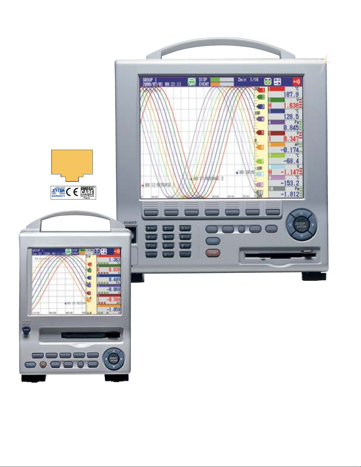
Paperless Recorder
RD-MV102-1
Starts at
$
2673
14 cm (5.5")
TFT Color Display
RD-MV210-1, $4454, shown smaller than actual size.
Ethernet
(10BASE-T)
⻬ Up to 12 Channels
on RD-MV100
⻬ Up to 30 Channels
on RD-MV200
RD-MV204-1
Starts at
$
4234
26 cm (10.4")
TFT Color Display
⻬ Programmable Inputs:
RTD, Thermocouple,
Voltage
⻬ TFT Color LCD for
Better Viewing
⻬ Removable Storage on
3.5" Floppy Disk, Zip
Disk, or PCMCIA ATA
Flash Memory Card
⻬ Data Collection Over
Ethernet Network
(Standard)
⻬ Network-Compatible
Sophisticated Software
⻬ Highly Reliable
Hardware
Today’s users want mobile capabilities
in all types of devices that use
information. Cellular phones and
notebook computers are embodiments
of this concept of mobility. With the
RD-MV100/200 OMEGA is now setting
the mobility standard for data loggers.
The RD-MV100/200’s internal memory
can store approximately 27 hours
of continuous data when recording
at 1-second intervals with a 6-channel
model, or 8 hours when using a
20-channel model. The RD-MV100/200
is standard equipped with an Ethernet
(10BASE-T) port for high-speed
communications. The Ethernet
capability makes it possible to form
a simple network of PCs and
RD-MV100/200 units using a hub or
connect the RD-MV100/200 to a LAN.
*Optional
* See page S-18 for details.
Page 2
S-16
S
Common Specifications
Removable Storage Medium:
3 options (3.5" floppy disk, zip disk,
PCMCIA ATA flash memory card)
Inputs: DC voltages, thermocouples,
resistance temperature detectors, and
digital inputs can be mixed
RD-MV100 External Dimensions:
Approx 225 H x 152 W x 240 mm D
(9 x 6 x 9.5")
Weight: Approx 4 kg (8.8 lb)
RD-MV200 External Dimensions:
Approx 338 H x 281 W x 252 mm D
(13 x 11 x 10")
Weight: Approx 7 kg (15.4 lb)
Input Unit:
Input Types: Floating unbalanced input,
inter-channel isolation; (however, a
common terminal is used for b terminals
of RTDs)
Measurement Intervals:
RD-MV102/104/204/208: 125 ms
RD-MV106/112/210/220/230: 1 second
(measurement interval is 2 seconds
when the A/D integrating time is set
to 100 ms)
Input Ranges, Measuring Ranges,
and Measurement/Display Accuracy:
(Reference operating conditions: 23
±2°C; 55 ±10% RH; supply voltage: 90 to
132, 180 to 250 Vac; supply frequency:
50/60 Hz ±1%; warmup time: 30 minutes
or longer; performance under conditions,
such as vibrations, which do not affect
equipment operations)
Reference Junction Compensation
(RJC): INT (internal)/EXT (external)
switching possible
RJC Accuracy: Type R, S, B, C: ±1°C;
Type K, J, E, T, N, L, U: ±0.5°C (when
measured at 0°C or higher)
Maximum Input Voltage: 2 Vdc or lower
voltage range and thermocouple: ±10 Vdc
(continuous); 6 V, 20 Vdc voltage range:
±30 Vdc (continuous)
Input Resistance: 2 Vdc or lower voltage
range and thermocouple: 10 MΩ or
greater; 6 V, 20 Vdc voltage range:
approx 1 MΩ
Input External Resistance:
DC Voltage, Thermocouple Input:
2 KΩ or less
RTD Input: 10 Ω or less per line
(equal on all 3 lines)
Input Bias Current: 10 nA or less
Maximum Common Mode Noise
Voltage: 250 Vac rms (50/60 Hz)
Common Mode Rejection Ratio:
120 dB (50/60 Hz ±0.1%; 500 Ω
unbalanced; negative terminal to ground)
Normal Mode Rejection Ratio:
40 dB (50/60 Hz ±0.1%)
Thermocouple Burnout: Sensor
ON/OFF switching possible; burnout
upscale/downscale switching possible
Calculation
Difference Calculation: Difference
calculation between any channels
Difference Calculation Range:
DCV, TC, RTD
Linear Scaling: Scaling range: DCV, TC,
RTD; scalable value: -30000 to 30000
Square Root Scaling:
Scaling range: DCV
Scalable value: -30000 to 30000
Display Unit
Display Colors: Trend and bar graph
displays: 12 colors for RD-MV100,
16 colors for RD-MV200
Background: white or black
Trend Display:
Direction: Vertical or horizontal
Number of Windows: Switching
between 4 (4 groups)
Thickness: 1, 2, or 3 dots
Waveform Update Rate: 15 or 30
seconds (125 ms measurement interval
model only); 1, 2, 5, 10, 20, or 30
minutes; or 1, 2, 4 hours (per div)
Bar Graph Display:
Direction: Vertical or horizontal
Number of Windows: Switching
between 4 (4 groups)
Scale: Can be set in range of 4 to 12
Horizontal Bar Graph Reference
Position: End or center
Update Rate: 1 second
Digital Display: Update rate: 1 second
Overview Display: Measurement values
and alarm status on all channels
Information Display: Alarm summary,
message summary, memory information,
media information, etc.
Other Displayed Information:
Memory status, scale values
(0, 100%, display ON/OFF switching
capability); grid (number of divisions can
be set between 4 and 12), and hours:
minutes; time (year/month/date,
hours/minutes/seconds); trip line
(thickness: 1, 2, or 3 dots); Messages
(maximum 16 characters, up to 8 types),
alarm marks
Data Reference Function
Data can be played back from internal
memory or a removable storage medium
Display Types: Split screen (divided in 2)
or whole screen; time axis operations:
Zoom-in/-out display, scrolling
Storage Functions
Removable Storage Drive: A drive for
the following types of media can be
selected when you place your order:
3.5" floppy disk (2HD), Zip disk, or
PCMCIA ATA flash memory card
Data Saving Method: Manual saving or
auto-saving
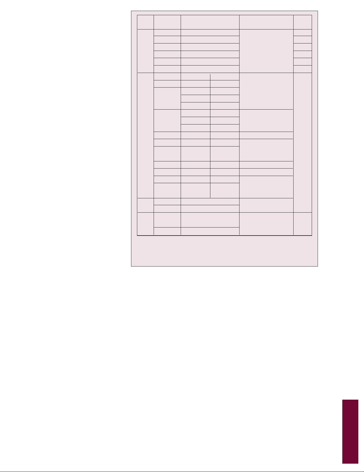
Input Range/Type
20 mV
60 mV
DCV
TC
RTD*5
*1 R, S, B, K, E, J, T, N: IEC584-1 (1995), DIN IEC584, JIS C 1602-1995
*2 C: W-5%, Rd/W-26%, Rd ASTM E988
*3 L: Fe-CuNi, DIN43710, U: Cu-CuNi, DIN43710
*4 Pt100: JIS C 1604-1997, IEC751-1995, DIN IEC751-1996,
JPt100: JIS C 1604-1989, JIS C 1606-1989
*5 Measuring current: i = 1 mA
200 mV
2 V
6 V
20 V
R*1
S*1
B*1
K*1
E*1
J*1
T*1
N*1
C*2
L*3
U*3
Pt100*4
JPt100*4
Voltage input
DI
Contact input
Measuring range
-20.00 to 20.00 mV
-60.00 to 60.00 mV
-200.00 to 200.00 mV
-2.000 to 2.000 V
-6.000 to 6.000 V
-20.00 to 20.00 V
0.0 to 1760.0C
0.0 to 1760.0C
0.0 to 1820.0C
-200.0 to 1370.0C
-200.0 to 800.0C
-200.0 to 1100.0C
-200.0 to 400.0C
0.0 to 1300.0C
0.0 to 2315.0C
-200.0 to 900.0C
-200.0 to 400.0C
-200.0 to 600.0C
-200.0 to 550.0C
OFF: Less than 2.4 V
ON: 2.4 V or greater
Contact ON/OFF
32 to 3200F
32 to 3200F
32 to 3200F
-328 to 2498F
-328.0 to 1472.0F
-328.0 to 2012.0F
-328.0 to 752.0F
32 to 2372F
-328.0 to 4199F
-328.0 to 1652.0F
-328.0 to 752.0F
Measurement accuracy
(digital display)
(0.1% of rdg + 2 digits)
(0.15% of rdg + 1C)
R, S: 0 to 100C, 3.7C;
100 to 300C, 1.5C B: 400 to
600C, 2C; if less than 400C,
accuracy is not guaranteed
(0.15% of rdg + 0.7C)
If -200 to -100C, then
(0.15% of rdg + 1C)
(0.15% of rdg + 0.5C)
(0.15% of rdg + 0.5C)
If -200 to -100C, then
(0.15% of rdg + 0.7C)
(0.15% of rdg + 0.7C)
(0.15% of rdg + 1C)
(0.15% of rdg + 0.5C)
If -200 to -100C, then
(0.15% of rdg + 0.7C)
(0.15% of rdg + 0.3C)
Digital display
maximum
resolution
10 V
10 V
100 V
1 mV
1 mV
10 mV
0.1C
Page 3

S-17
Manual Saving: Saves data when a
removable storage medium is inserted
Auto-Saving
Saving Display Data: Saves data to a
removable storage medium periodically
(every 10 minutes to 31 days)
Saving Event Data: Saves data to a
removable storage medium
periodically (every 3 minutes to 31
days when trigger is not yet specified)
or saves data when sampling period
ends (when trigger is specified)
Data Saving Intervals
Display Data Files: Interval varies
according to the waveform update rate
Event Data Files:
Sampling interval is specified
Event Data File Sampling Intervals:
RD-MV102/104/204/208: 125, 250,
500 ms; 1, 2, 5, 10, 30, 60, or 120 seconds
Measurement Data Files: The following
two types of files can be created:
1. Event data files (to save instantaneous
values sampled at specified sampling
intervals)
2. Display data files (to save maximum and
minimum values occurring in display
update interval in measurement data
sampled at measurement interval)
The two files can be combined as follows:
1. Event data file (trigger only)
plus display data file
2. Display data file only
3. Event data file only
Data Format: OMEGA
®
standard format
(binary format)
Display Data
Measurement Data: 4 bytes per data
Calculation Data: 8 bytes per data
Event Data
Measurement Data: 2 bytes per data;
Calculation Data: 4 bytes per data
Manual Sampling Data
Storage Trigger: Key input or contact input
Data Format: ASCII format
Maximum Stored Data: 50 data
TLOG Data (with calculation option only):
Time series integrated (totalized) value,
maximum value, minimum value,
average value, max/min value
Storage Trigger: Data saved when
TLOG time is up
Report Data (with calculation
option only): Periodic average value,
maximum value, minimum value, and
integrated (totalized) value
Types: hourly reports, daily reports,
daily + weekly reports, daily + monthly
reports
Data Format: ASCII
Screen Copying Function
Copying Method: Key input
Data Format: PNG
Output to: Removable storage medium
or online output
Trigger Functions
Event Data File: Select FREE, TRIG, or
ROTATE mode
Display Data + Event Data File:
Select TRIG or ROTATE mode
Trigger Source: Key input, remote
control (optional), alarm
Pretrigger: Works with event data;
0, 5, 25, 50, 75, 95, or 100%
Alarm Functions
Maximum Number: A maximum of
4 alarms can be set on each channel
Alarm Types: High/low limits,
high/low difference limits, rate of
change increase/decrease limits
Rate of Change Alarm
Time Interval:
Measurement interval x 1 to 15
Display: Status (alarm type) and
common alarm display in digital display
area when alarm occurs; hold/no hold
switching capability
Hysteresis: ON (0.5% of display
span)/OFF switching (common to
all channels/levels)
Outputs: 2, 4, 6, 12, or 24 (12 and 24
can be specified for RD-MV200 only)
operation excitation/no excitation,
hold/no hold switching capability
Storage
Stored Information: Alarm
occurrence/clear time, alarm type
Number of Saved Items:
Maximum 120 (most recent)
COMMUNICATION FUNCTIONS
Network Type: Ethernet (10BASE-T)
Basic Protocol: TCP/IP
File Transfer Function: Automatic
transfer from RD-MV100/200 (FTP client
protocol); file transfer in response to
request from host computer (FTP
server protocol)
Real Time Monitor Function:
Real time online monitoring of
RD-MV100/200 measurement data
(proprietary protocol)
Transferable Files: Display data files,
event data files, report data, and
screenshot data
FTP Server Functions: Directory
operations on a removable storage
medium, file output, file deletion, and
information on available memory space
in a storage medium
Display:
RD-MV100: 5.5" TFT color LCD
(320 x 240 dots)
RD-MV200: 10.4" TFT color LCD
(640 x 480 dots)
Supply Voltage
AC Power Supply: 90 to 132,
180 to 250 Vac, 50/60 Hz, 80 VA
DC Power Supply: 10 to 18 Vdc, 42 VA
Ambient: 5 to 40°C
Optional Specifications
Alarm Output Relay Contacts
(/A1, /A2, /A3, /A4, /A5) :
250 Vdc/0.1 A (resistance load),
250 Vac (50/60 Hz)/3 A. NO-C-NC
(excitation/no excitation, AND/OR,
hold/no hold switching capability)
Serial Communications (/C2, /C3):
RS232 or RS422-A/485 (4-wire halfduplex multidrop connection); 1200, 2400,
4800, 9600, 19200, 38400 bps; 7 or 8 bits,
1 stop bit, odd/even/none parity
Fail/Memory End Output (/F1):
Relay output from back side before start
time specified for display data file
overwriting or when system abnormality
occurs (1, 2, 5, 10, 20, 50, or 100 hours
can be specified)
Screw Input Terminals (/H3):
(/H3 option for RD-MV100 only;
specified suffix code for RD-MV200)
The standard clamp input terminals are
replaced with screw type input terminals
Mathematical Calculation and Report
Functions (/M1):
Addition, subtraction, multiplication, division,
square root, absolute value, common
logarithm, exponent, power, relationships
(<, >, =, ≠), logical calculations (AND, OR,
NOT, XOR), time series data average;
maximum, minimum, and integrated
(totalized) values; up to 12 constants can be
set for RD-MV100, 30 for RD-MV200
Report Types: Hourly reports, daily
reports, daily + weekly reports,
daily + monthly reports
Calculation Types: Average,
maximum, minimum, and integrated
(totalized) values
Remote Control (/R1):
Memory start/stop, event data file
trigger, time adjustment, calculation
start/stop, calculation data reset, manual
sampling, message writing, alarm ACK
Application Software
DAQSTANDARD (included)
DATA VIEWER: Configuration
software (see next page)
DAQEXPLORER (sold separately)
Functions include:
Desktop (file transfers, configurations,
etc., using operations on desktop); data
monitoring; hardware configurations
(online or using a removable storage
medium; data viewer; printout of
playback data; file conversion to ASCII,
Lotus 1-2-3, and MS-Excel formats)
RD-MV106-1,
$2784, shown
smaller than
actual size.
Page 4

S-18
S
Digital Display Bar Graph Display Historical Trend Display
Overview Display Information Display 4-Split Screen
Data Viewer
The data viewer can be used to convert file
formats and play back data files saved on
the RD-MV100/RD-MV200 (event data,
display data, TLOG data files), and data files
transferred to a file server using a protocol
such as FTP (event data, display data,
TLOG data files); the file conversion
functions let you convert RD-MV100/200
data files to ASCII format, as well as the
formats of off-the-shelf spreadsheet
programs such as Lotus 1-2-3 and
MS-Excel
Configuration Software
The configuration software can be used to
enter various RD-MV100/200 configurations
either online or using a removable medium
To Order
(Specify Model Number)
Model No. Price Description
RD-MV102-1 $2673 2-channel recorder
RD-MV104-1 3121 4-channel recorder
RD-MV106-1 2784 6-channel recorder
RD-MV112-1 3898 12-channel recorder
RD-MV204-1 4234 4-channel recorder
RD-MV208-1 4741 8-channel recorder
RD-MV210-1 4454 10-channel recorder
RD-MV220-1 5292 20-channel recorder
RD-MV230-1 6125 30-channel recorder
Comes with floppy disk storage, 120/240 Vac power, 3-pin power inlet with
UL/CSA cable, clamp input terminals, and complete operator’s manual.
To order Zip disk or ATA flash card change the “-1” to “-2” or “-3”
respectively and add $166. To order with 12 Vdc power input (includes
AC adaptor), add suffix “-2” to model number and add $386. To order
with different power cord add suffix “-F” for VDE, “-R” for SAA, or “-S”
for BS cable to model number. No additional cost.
Ordering Example: RD-MV106-1/A3/C3, 6-channel 120/240 Vac model
with floppy disk storage, alarm relay output with 6-points and RS422-A485
interface, $2784 + 414 + 187 = $3385. OCW-3, OMEGACARESMextends
standard 2-year warranty to a total of 5 years ($350), $3385 + 350 = $3735.
Options (Add as Suffix)
Model No. Price Description
/A1 $166 Alarm: 2 points (RD-MV100 ONLY)
/AR1 303 Alarm: 2 points & remote control
(RD-MV200 ONLY)
/A2 278 Alarm: 4 points (RD-MV100 ONLY)
/AR2 441 Alarm: 4 points & remote control
(RD-MV200 ONLY)
/A3 414 Alarm: 6 points
/A4 827 Alarm: 12 points (RD-MV200 ONLY)
/A5 1240 Alarm: 24 points (RD-MV200 ONLY)
/C2 187 RS232C interface
/C3 187 RS422-A/485 interface
/D5 275 VGA output (RD-MV200 ONLY)
/F1 187 FAIL/memory end output relay
/H3 0 Screw input terminals (RD-MV100 ONLY)
/M1 221 Mathematical function
(including report function)
/R1 166 Remote control
-CE 375 CE marked
Only one /A* Type option per unit.
Only one /C* Type option per unit.
With /F1 option the /A3 (on RD-MV100)
or /A5 (on RD-MV200) is not available.
OMEGACARESMextended warranty program is
available for models shown on this page.
OMEGACARESMcovers parts, labor, and
equivalent loaners. Ask your sales representative
for full details when placing an order.
Model No. Price Description
RD-DXA200-02 $438 DAQEXPLORER software
RD-MV-A1053MP 20 Zip disk
RD-MV-M1223RU-A 158 ATA 128 MB flash memory card
ME-1200 150 Reference Book: Introduction to the Design
and Behavior of Bolted Joints
Accessories
Display Types
MOST POPULAR MODELS HIGHLIGHTED!
Page 5

One Omega Drive | Stamford, CT 06907 | 1-888-TC-OMEGA (1-888-826-6342) | info@omega.com
EPG05
www.omega.com
UNITED KINGDOM
www. omega.co.uk
Manchester, England
0800-488-488
UNITED STATES
www.omega.com
1-800-TC-OMEGA
Stamford, CT.
CANADA
www.omega.ca
Laval(Quebec)
1-800-TC-OMEGA
GERMANY
www.omega.de
Deckenpfronn, Germany
0800-8266342
Karviná, Czech Republic
FRANCE
www.omega.fr
Guyancourt, France
088-466-342
CZECH REPUBLIC
www.omegaeng.cz
596-311-899
BENELUX
www.omega.nl
Amstelveen, NL
0800-099-33-44
More than 100,000 Products Available!
Temperature
Calibrators, Connectors, General Test and Measurement
Instruments, Glass Bulb Thermometers, Handheld Instruments
for Temperature Measurement, Ice Point References,
Indicating Labels, Crayons, Cements and Lacquers, Infrared
Temperature Measurement Instruments, Recorders Relative
Humidity Measurement Instruments, RTD Probes, Elements
and Assemblies, Temperature & Process Meters, Timers and
Counters, Temperature and Process Controllers and Power
Switching Devices, Thermistor Elements, Probes and
Assemblies,Thermocouples Thermowells and Head and Well
Assemblies, Transmitters, Wire
Flow and Level
Air Velocity Indicators, Doppler Flowmeters, Level
Measurement, Magnetic Flowmeters, Mass Flowmeters,
Pitot Tubes, Pumps, Rotameters, Turbine and Paddle Wheel
Flowmeters, Ultrasonic Flowmeters, Valves, Variable Area
Flowmeters, Vortex Shedding Flowmeters
pH and Conductivity
Conductivity Instrumentation, Dissolved Oxygen
Instrumentation, Environmental Instrumentation, pH
Electrodes and Instruments, Water and Soil Analysis
Instrumentation
Data Acquisition
Auto-Dialers and Alarm Monitoring Systems,
Communication Products and Converters, Data
Acquisition and Analysis Software, Data Loggers
Plug-in Cards, Signal Conditioners, USB, RS232, RS485
and Parallel Port Data Acquisition Systems, Wireless
Transmitters and Receivers
Pressure, Strain and Force
Displacement Transducers, Dynamic Measurement
Force Sensors, Instrumentation for Pressure and Strain
Measurements, Load Cells, Pressure Gauges, Pressure
Reference Section, Pressure Switches, Pressure Transducers,
Proximity Transducers, Regulators,
Strain Gages, Torque Transducers, Valves
Heaters
Band Heaters, Cartridge Heaters, Circulation Heaters,
Comfort Heaters, Controllers, Meters and Switching
Devices, Flexible Heaters, General Test and Measurement
Instruments, Heater Hook-up Wire, Heating Cable
Systems, Immersion Heaters, Process Air and Duct,
Heaters, Radiant Heaters, Strip Heaters, Tubular Heaters
click here to go to the omega.com home page
 Loading...