

Page 1
Portable Paperless Recorders
and Data Acquisition Stations
RD-MV1000 and
RD-MV2000 Series
Starts at
$
3535
RD-MV1006, $3535, shown
smaller than actual size.
⻬ Multi-Channel Universal
Inputs, Up to 48 Input
Channels
⻬ Secure High Capacity
Memory with Internal
Memory of 400 MB
⻬ Choice of Compact Flash
and USB Removable
Storage Media
⻬ Detachable Input
Terminals Simplify
Field Wiring
⻬ Advanced Network
Connectivity with Email,
File Transfer, and Web
Server Functions
⻬ Standard Equipped
with 2 USB Ports
⻬
High Speed Sampling
(25 ms for Every Channel)
⻬ Clear Wide-Angle
LCD Monitor
⻬ Integral Bar Graph
Display
⻬ Compliance with
Safety Standards
and EMC Standards
⻬ Isolated Channel Inputs
for DC Voltage and
Thermocouple Inputs
⻬ Recorders Can Save
Data Files in a Text
File Format
The RD-MV1000/MV2000 portable
paperless recorders are high
performance and easy-to-use test
instruments that handle a wide
range of measurements in your lab,
plant, or test stand. These recorders
have powerful stand-alone data
logging capability. The units record
on-site changes in temperature,
voltage, current, flow and pressure.
The RD-MV1000 features 24
channel-input and RD-MV2000 has
48 channels. Both models feature
200 MB of memory, allowing data
to be stored for approximately 70
days at one-second intervals with
a 12-channel model. The recorders
feature guidance messages for
set-up and entering of settings.
S-15a
RD-MV2008, $5655.
Measured data can be stored in text
format on removable storage media
for further processing and data
back up on a personal computer
using standard software. The
RD-MV1000 features a 140 mm
(5.5") color TFT-LCD display and
the RD-MV2000 has a 264 mm
(10.4") display.
The RD-MV1000/MV2000 series
is a portable recorder that displays
real-time measured data on a color
LCD and saves data on a Compact
Flash memory card (CF card).
It can be hooked up to network
via Ethernet, which enables to
inform by E-mail and to monitor
on Web site as well as to transfer
files by using FTP. Also, it can
communicate with Modbus
or Modbus TCP.
The data saved on a CF card can
be converted by data conversion
software to MS-Excel or text format
file, facilitating processing on a PC.
Not only this, the Viewer software
allows a PC to display waveforms
on its screen and to print out
waveforms.
®
RTU
S
Page 2
General Specifications
WW
UU
RD-MV1000
External Dimensions:
189 W x 177 H x 259 D mm
(7.4 x 7 x 10.2")
Weight: Approx. 3.5 kg (7.7 lb)
(MV1024)
RD-MV2000
External Dimensions:
307 W x 273 H x 260 D mm
(12.1 x 10.7 x 10.2")
Weight: Approx. 5.6 kg (12.3 lb)
(RD-MV2048)
Input
Number of Inputs:
RD-MV1000: 4, 6, 8, 12, or
24 channels
RD-MV2000: 8, 10, 20, 30, 40 or
48 channels
Measurement Intervals:
RD-MV1004, RD-MV1008,
RD-MV2008: 125 ms, 250 ms,
or 25 ms in high-speed mode*
RD-MV1006, RD-MV1012,
RD-MV1024, RD-MV2010,
RD-MV2020, RD-MV2030,
RD-MV2040, RD-MV2048: 1 s
(100 ms not possible for A/D
integration time), 2 s, 5 s, or 125 ms
in high-speed mode*
* A/D integration time is fixed at 1.67 ms in
high-speed mode
Points to Consider when Using
High-Speed Mode: When using high-
speed mode (an A/D integration time of
1.67 ms) with the RD-MV1000/MV2000,
power supply noise and other factors
may cause the measured values
to fluctuate. If this is the case, then
measure using Normal mode (an
A/D integration time of 16.7 ms,
20 ms, or 100 ms)
Input Method: Floating unbalanced
input, isolated between channels
(b terminal of RTD input is common)
A/D Resolution: ±20000 (16 bits A/D)
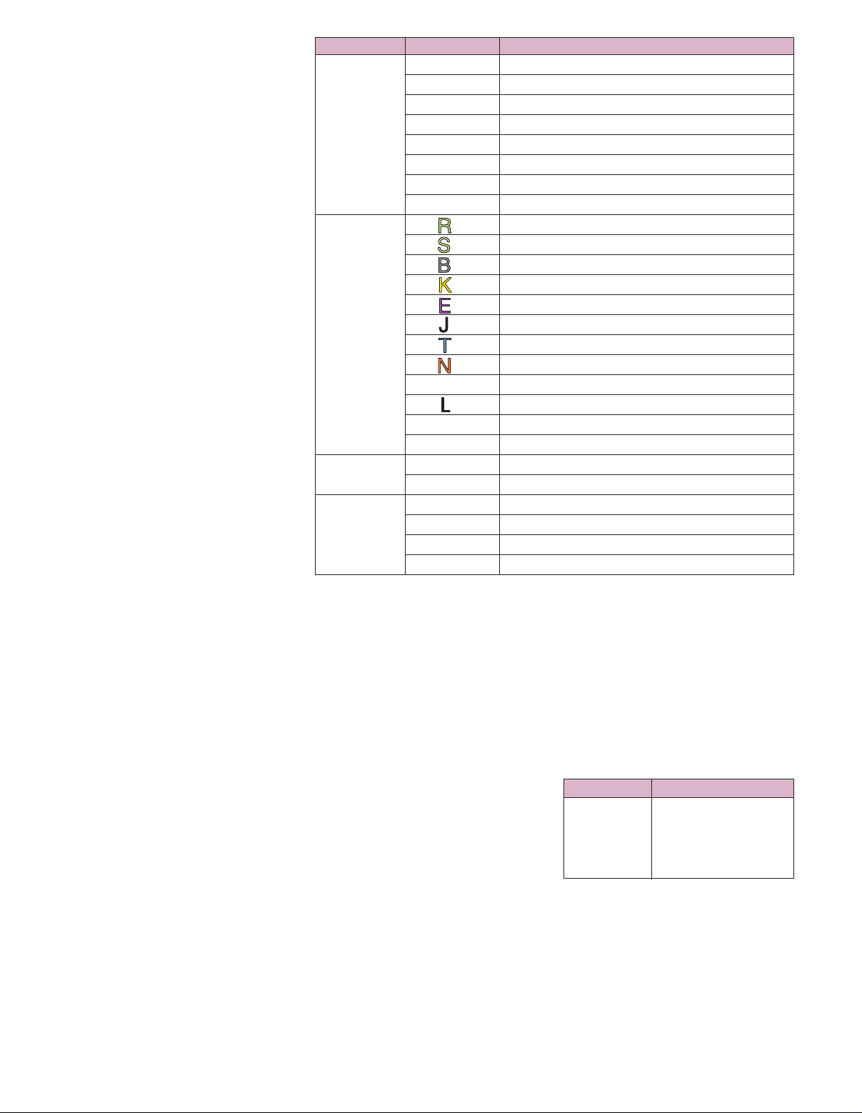
Input Types:
DCV (DC Voltage): 20, 60, 200 mV,
2, 6, 20, 50 V, 1 to 5 V
TC (Thermocouple Type): R, S, B,
K, E, J, T, N, W, L, U, WRe
Input Type Range Measuring Range
20 mV -20.000 to 20.000 mV
60 mV -60.00 to 60.00 mV
200 mV -200.00 to 200.00 mV
DC 2V -2.0000 to 2.0000V
6V -6.000 to 6.000V
1 to 5V 0.800 to 5.200V
20V -20.000 to 20.000V
50V -50.00 to 50.00V
*1 0 to 1760°C (32 to 3200°F)
*1 0 to 1760°C (32 to 3200°F)
*1 0 to 1820°C (32 to 3308°F)
*1 -200 to 1370°C (-328 to 2498°F)
*1 -200 to 800°C (-328 to 1472°F)
T/C *1 -200 to 1100°C (-328 to 2012°F)
*1 -200 to 400°C (-328 to 752°F)
*1 0 to 1300°C (32 to 2372°F)
*2 0 to 2315°C (32 to 4199°F)
*3 -200 to 900°C (-328 to 1652°F)
*3 -200 to 400°C (-328 to 752°F)
WRe *4 0 to 2400°C (32 to 4352°F)
RTD
Pt100*5 -200 to 600°C (-328 to 1112°F)
JPt100*5 -200 to 550°C (-328 to 1022°F)
DCV OFF: less than 2.4V
DI
Input ON: more than 2.4V
Contact Contact ON/OFF
Input
RTD (Resistance Temperature
Detector): Pt100, JPt100
DI: At the contact input or the
TTL level
DCA: DC current; with external
shunt resistor
Measuring range, measurement
accuracy, and display resolution by
typical input type
Display
Display Device:
RD-MV1000: 140 mm (5.5") TFT
color LCD (320 x 240 dots)
RD-MV2000: 264 mm (10.4") TFT
color LCD (640 x 480 dots)
Note: The LCD may contain some pixels that
are always lighted or that never light, and
variations in brightness may occur due to the
characteristics of liquid crystals. Please note
that these are not defects.
Trend Display: Vertical, horizontal,
horizontal wide, separated horizontal
Digital Display
Update Rate: 1 s
Tag Display: Number of characters
16 maximum
Message Display: Number of
characters 32 maximum
Historical Display Function:
Allows for the display of data stored
to internal or external memory
Data Saving Function:
External Storage Media: Compact
flash memory card (CF card)
Internal Memory Media:
Flash memory
Memory Size: 200 MB
Sample Time: Examples of internal
memory sample times with the MV1012
recording only event data files for
12 measuring channels and no
calculation channels (approx)
Save Interval Sample Time (200 MB)
125 ms 9 days
1 s 75 days
5 s 370 days
10 s 750 days
60 s 12.5 years
Manual Save: Saves data files to the
internal memory manually; save all data
or only selected data
Auto Save: Save displayed data to the
CF card at a set interval
Save Event Data: Saves data to the
CF card at a set interval (in free
trigger mode); save when finished
sampling (when setting the trigger)
S-15b
Page 3

Data Formats: When saving to external
media, both event data and display data
can be saved in either binary or text
format (data is always stored
to internal memory in binary format)
Event Data Sampling Period:
RD-MV1004/RD-MV1008/
RD-MV2008: Selectable from
25, 125, 250, 500 ms; 1, 2, 5, 10,
30, 60, 120, 300, 600 s
RD-MV1006/RD-MV1012/
RD-MV1024/RD-MV2010/
RD-MV2020/RD-MV2030/
RD-MV2040/RD-MV2048:
Selectable from 125, 250 ms;
1, 2, 5, 10, 30, 60, 120, 300, 600 s
Trigger Function: Data can be saved
using Free mode or Trigger mode
Trigger Mode: The user must set the
data length, pre-trigger, and trigger
source
Snapshot Function: Saves the
displayed screen image data to a CF card
Data File Loading: Data files saved to
a CF card or to USB memory can be
loaded and displayed
Loading and Saving Setup Data:
Settings data can be saved and loaded
in binary format
Alarm Functions
Number of Alarm Levels:
Up to 4 levels for each channel
Alarm Types: High/low limit, delay
high/low limit, difference high/low limit,
high/low limit on rate of change
Display: When an alarm occurs, the
state (the alarm type) or common alarm
state appears on the digital display
Security Features
Description: You can customize key
lock and login security functions for any
transmission or key command
Key Lock: Sets a password-protected
key lock on all command keys and
FUNC screen operations
Login: Limits access to the
RD-MVAdvanced with a login that
prompts for username and password
Communication Features
(Ethernet)
Electrical Specifications: IEEE 802.3
compliant (DIX frame)
Transmission Media: Ethernet
(10BASE-T)
Protocols: TCP, UDP, IP, ICMP, ARP,
DHCP, HTTP, FTP, SMTP, SNTP,
Modbus, and MV dedicated protocol
E-mail Transmission Functions
(E-mail Client): Automatically sends
an e-mail in response to alarms and
other events
FTP Client Functions: Automatically
sends data files to a FTP server
FTP Server Functions: Can transfer
and delete files, manipulate directories,
and produce file lists remotely from a
network computer
Web Server Function: Displays MV
screen images on a Web browser
SNTP Client Function: Queries a set
SNTP server for the time and
synchronizes with it
SNTP Server Function: Transmits the
MV time settings via SNTP protocol
DHCP Client Function: Automatically
retrieves the network address settings
from a DHCP server
Modbus Server Function:
Data can be read from the MV
using the Modbus protocol
USB Interface
USB Interface: USB specification
1.1 host
Ports: 2 (front and back)
Connectable Devices: 104 keyboards
(US) compliant with USB HID Class
Version 1.1
External Media: USB flash drive
(not all types of USB memory are
guaranteed to work)
Power Supply
AC Power Supply: Rated supply
voltage 100 to 264 Vac (auto switching)
Operating Supply Voltage Range:
90 to 132, 180 to 264 Vac
DC Power Supply: Rated supply
voltage 12 Vdc/24 Vdc
Operating Supply Voltage Range:
10.0 to 28.8 Vdc
Other Specifications
Dielectric Strength
Power Supply to Ground Terminal
100 Vac/240 Vac: 2300 Vac
(50/60 Hz), 1 min
Power Supply to Ground Terminal,
12 Vdc: 500 Vac (50/60 Hz), 1 min
Contact Output Terminal to Ground
Terminal: 1600 Vac (50/60 Hz), 1 min
Measuring Input Terminal to
Ground Terminal: 1500 Vac
(50/60 Hz), 1 min
Between Measuring Input Terminals:
1000 Vac (50/60 Hz), 1 min (except for
b-terminal of RTD input of RD-MV1006,
RD-MV1012, RD-MV1024, RD-MV2010,
RD-MV2020, RD-MV2030, RD-MV2040
and RD-MV2048)
Between Remote Control Terminal to
Ground Terminal: 1000 Vdc, 1 min
Between Pulse Input Terminal to
Ground Terminal: 1000 Vdc, 1 min
Safety and EMC Standards
CSA: CSA22.2 No1010.1 Installation
category II*, pollution degree 2**
CE:
EMC Directive: EN61326 compliance
(Emission: Class A, Immunity:
Annex A); EN61000-3-2 compliant;
EN61000-3-3 compliant;
EN55011 compliant
Low Voltage Directive: EN61010-1
compliant, measurement category
II***, pollution degree 2**
C-Tick: AS/NZS CISPR11 compliant,
Class A Group 1
* Installation category (over voltage
category) II: describes a number which
defines a transient over voltage condition.
It implies the regulation for impulse withstand
voltage. “II” applies to electrical equipment
which is supplied from fixed installations like
distribution boards.
** Pollution degree: describes the degree
to which a solid, liquid, or gas which
deteriorates dielectric strength or surface
resistivity is adhering. “2” applies to normal
indoor atmosphere. Normally, only
non-conductive pollution occurs.
*** Measurement category II: applies to
measuring circuits connected to low voltage
installation, and electrical instruments
supplied with power from fixed equipment
such as electric switchboards.
Normal Operating Conditions
Power Consumption
RD-MV1000 Power Consumption
Supply Voltage LCD Off Normal Maximum
100 Vac 15 VA 30 VA 45 VA
240 Vac 25 VA 40 VA 60 VA
12 Vdc 7 VA 14 VA 24 VA
RD-MV2000 Power Consumption
Supply Voltage LCD Off Normal Maximum
100 Vac 28 VA 40 VA 65 VA
240 Vac 38 VA 54 VA 90 VA
12 Vdc 9 VA 18 VA 35 VA
S
S-15c
Page 4

Supply Voltage:
AC Power Supply: 90 to 132,
180 to 250 Vac
DC Power Supply: 10.0 to 28.8 Vdc
Supply Frequency: 50 Hz ±2%,
60 Hz ±2%
Ambient Temperature: 0 to 40°C
(32 to 104°F)
Ambient Humidity: 20 to 80% RH
@ 5 to 40°C (41 to 104°F)
Warm-Up Time: At least 30 minutes
Standard Performance
Measuring Accuracy: The following
specifications apply to operation of the
recorder under standard operation
conditions
Temperature: 23 ±2°C (36°F)
Humidity: 55% ±10% RH
Power Supply Voltage: 90 to 132
or 180 to 250 Vac
Power Supply Frequency:
50/60 Hz ±1%
Warm-Up Time: At least 30 min
Other ambient conditions such as vibration
should not adversely affect recorder
operation.
Measurement Accuracy: In case of
scaling (digits) = measurement accuracy
(digits) x scaling span (digits)/
measurement span (digits) + 2 digits;
decimals are rounded off to the next
highest number
Reference Junction Compensation
Accuracy:
Types R, S, W, WRe: ±1°C (34°F)
Types K, J, E, T, N, L, U: ±0.5°C
(31°F)
Types B: Internal RJC is fixed to
0°C (32°F) (above 0°C (32°F), input
terminal temperature is balanced)
Maximum Allowable Input Voltage:
±60 Vdc (continuous) for all input ranges
Input Resistance:
DCV Ranges of 200 mVdc or Less
and TC: Approx 10 MΩ or more
More Than 2 Vdc Ranges: Approx
1 MΩ
Input Source Resistance:
DCV, TC: 2 kΩ or less
RTD (Pt100): 10Ω or less per wire
(the resistance of all three wires must
be equal)
Input Bias Current: 10 nA or less
(approx 100 nA for TC range with
burnout function)
Maximum Common Mode Noise
Voltage: 250 Vrms AC (50/60 Hz)
Maximum Noise Voltage Between
Channels: 250 Vrms AC (50/60 Hz)
Interference Between Channels:
Measurement Display
Input Range Accuracy** Resolution
DCV 1 to 5V ±0.05% of rdg + 3 digits 1 mV
Thermocouple* K ±0.15% of rdg + 0.7°C 0.1°C
(33.3°F) (32.2°F)
RTD Pt100 ±0.15% of rdg + 0.3°C 0.1°C
(32.5°F) (32.2°F)
* Does not include the accuracy of reference junction compensation.
** When the integration time is 16.7 ms or more.
120 dB (when the input source
resistance is 500Ω and the inputs to
other channels are 60 V)
Common Mode Rejection Ratio:
A/D Integration Time 20 ms:
More than 120 dB (50 Hz ±0.1%,
500Ω imbalance between the
minus ground)
A/D Integration Time 16.7 ms:
More than 120 dB (60 Hz ±0.1%,
500Ω imbalance between the
minus ground)
A/D Integration Time 1.67 ms:
More than 80 dB (50/60 Hz ±0.1%,
500Ω imbalance between the
minus ground)
Normal Mode Rejection Ratio:
A/D Integration Time 20 ms:
More than 40 dB (50 Hz ±0.1%)
A/D Integration Time 16.7 ms:
More than 40 dB (60 Hz ±0.1%)
A/D Integration Time 1.67 ms:
Display Types
Digital Display Bar Graph Display Historical Trend Display
Overview Display Information Display 4-Split Screen
Processor: Pentium 4.3 GHz or higher
Memory: 2 GB or more
Hard Disk: Free area of at least 100 MB
Display Card: Compatible with
Windows 2000/XP/Vista
®
Configuration Software:
Setting Mode: Configuration of
setting mode and basic setting mode
Configuration via Communication:
Configuration of setting mode and
basic setting mode without
communication configuration
(ex. IP address)
50/60Hz is not rejected
Optional Specifications
Alarm Output Relays
(/A2, /A4, /A6, /A12*)
Output points: Choose from 2, 4, 6,
or 12*
* Only with the RD-MV2000.
Serial Communication (/C2, /C4)
Media: EIA RS-232 (/C2) and
RS-422/485 (four wire) (/C3) compatible
Protocols: The dedicated protocol and
the Modbus (master/slave) protocol
Settings/Measurement Server
Functions: Using the dedicated
protocol, the following functions are
available
Settings and Commands:
Equivalent to the unit’s key
commands
Data Viewer Software:
Number of Display Channels:
32 channels per group, 50 groups
maximum
Viewer Function: Waveform display,
digital display, circular display, list
display, report display etc.
Data Conversion: File conversion to
ASCII, Lotus 1-2-3 or MS-Excel format
S-15d
Page 5

RD-MV2008,
Extended Warranty
Program
SM
$5655, shown
smaller than
actual size.
RD-MV1006, $3535, shown
smaller than actual size.
MOST POPULAR MODELS HIGHLIGHTED!
To Order (Specify Model Number)
Model No. Price Description
RD-MV1004 $3875 4 input clamp terminal, 400 MB internal memory, CF card plus USB,
100 to 240 Vac, UL/CSA power cord
RD-MV1006 3535 6 input clamp terminal, 400 MB internal memory, CF card plus USB,
100 to 240 Vac, UL/CSA power cord
RD-MV1008 5690 8 input clamp terminal, 400 MB internal memory, CF card plus USB,
100 to 240 Vac, UL/CSA power cord
RD-MV1012 4765 12 input clamp terminal, 400 MB internal memory, CF card plus USB,
100 to 240 Vac, UL/CSA power cord
RD-MV1024 5690 24 input clamp terminal, 400 MB internal memory, CF card plus USB,
100 to 240 Vac, UL/CSA power cord
RD-MV2008 5655 8 input clamp terminal, 400 MB internal memory, CF card plus USB,
100 to 240 Vac, UL/CSA power cord
RD-MV2010 5315 10 input clamp terminal, 400 MB internal memory, CF card plus USB,
100 to 240 Vac, UL/CSA power cord
RD-MV2020 6240 20 input clamp terminal, 400 MB internal memory, CF card plus USB,
100 to 240 Vac, UL/CSA power cord
RD-MV2030 7215 30 input clamp terminal, 400 MB internal memory, CF card plus USB,
100 to 240 Vac, UL/CSA power cord
RD-MV2040 8105 40 input clamp terminal, 400 MB internal memory, CF card plus USB,
100 to 240 Vac, UL/CSA power cord
RD-MV2048 8825 48 input clamp terminal, 400 MB internal memory, CF card plus USB,
100 to 240 Vac, UL/CSA power cord
Options (Add Suffix) (Options are not field installable)
Add’l
Order Suffix Price Description
-DC $410 12 Vdc power supply (AC adaptor is included)
-A2* 160 Alarm output 2 points
-A4* 305 Alarm output 4 points
-A6* 465 Alarm output 6 points
(1)
-A12*
870 Alarm output 12 points
-C2** 210 RS232 interface
-C4** 210 RS422/485 interface
* These options cannot be specified together.
** These options cannot be specified together.
(1) Only available with RD-MV2000 models.
OMEGACARESMextended warranty program
is available for models shown on this page.
Ask your sales representative for full details
when placing an order. OMEGACARE
covers parts, labor and equivalent loaners.
SM
Accessories
Model No. Price Description
RD-MV1000-RACK $110 Rack mount adaptor for RD-MV1000 series
RD-MV2000-RACK 100 Rack mount adaptor for RD-MV2000 series
Comes complete with operator’s manual on CD, power cable, quick reference guide, terminal screws and the DAQ STANDARD software (CD),
CF card (128 MB). Software is compatible with Windows 2000/XP/Vista.
Ordering Examples: RD-MV1012, 12 input recorder with 400 MB internal memory, CF card, USB port, UL/CSA power cord, $4765.
OCW-3, OMEGACARESMextends standard 2-year warranty to a total of 5 years ($350) $4765 + 350 = $5115.
RD-MV1006-A6, 6 input recorder with 400 MB internal memory, CF card, USB port, UL power cord and six alarm outputs, $4000.
S-15e
S
Page 6

One Omega Drive | Stamford, CT 06907 | 1-888-TC-OMEGA (1-888-826-6342) | info@omega.com
EPG05
www.omega.com
UNITED KINGDOM
www. omega.co.uk
Manchester, England
0800-488-488
UNITED STATES
www.omega.com
1-800-TC-OMEGA
Stamford, CT.
CANADA
www.omega.ca
Laval(Quebec)
1-800-TC-OMEGA
GERMANY
www.omega.de
Deckenpfronn, Germany
0800-8266342
Karviná, Czech Republic
FRANCE
www.omega.fr
Guyancourt, France
088-466-342
CZECH REPUBLIC
www.omegaeng.cz
596-311-899
BENELUX
www.omega.nl
Amstelveen, NL
0800-099-33-44
More than 100,000 Products Available!
Temperature
Calibrators, Connectors, General Test and Measurement
Instruments, Glass Bulb Thermometers, Handheld Instruments
for Temperature Measurement, Ice Point References,
Indicating Labels, Crayons, Cements and Lacquers, Infrared
Temperature Measurement Instruments, Recorders Relative
Humidity Measurement Instruments, RTD Probes, Elements
and Assemblies, Temperature & Process Meters, Timers and
Counters, Temperature and Process Controllers and Power
Switching Devices, Thermistor Elements, Probes and
Assemblies,Thermocouples Thermowells and Head and Well
Assemblies, Transmitters, Wire
Flow and Level
Air Velocity Indicators, Doppler Flowmeters, Level
Measurement, Magnetic Flowmeters, Mass Flowmeters,
Pitot Tubes, Pumps, Rotameters, Turbine and Paddle Wheel
Flowmeters, Ultrasonic Flowmeters, Valves, Variable Area
Flowmeters, Vortex Shedding Flowmeters
pH and Conductivity
Conductivity Instrumentation, Dissolved Oxygen
Instrumentation, Environmental Instrumentation, pH
Electrodes and Instruments, Water and Soil Analysis
Instrumentation
Data Acquisition
Auto-Dialers and Alarm Monitoring Systems,
Communication Products and Converters, Data
Acquisition and Analysis Software, Data Loggers
Plug-in Cards, Signal Conditioners, USB, RS232, RS485
and Parallel Port Data Acquisition Systems, Wireless
Transmitters and Receivers
Pressure, Strain and Force
Displacement Transducers, Dynamic Measurement
Force Sensors, Instrumentation for Pressure and Strain
Measurements, Load Cells, Pressure Gauges, Pressure
Reference Section, Pressure Switches, Pressure Transducers,
Proximity Transducers, Regulators,
Strain Gages, Torque Transducers, Valves
Heaters
Band Heaters, Cartridge Heaters, Circulation Heaters,
Comfort Heaters, Controllers, Meters and Switching
Devices, Flexible Heaters, General Test and Measurement
Instruments, Heater Hook-up Wire, Heating Cable
Systems, Immersion Heaters, Process Air and Duct,
Heaters, Radiant Heaters, Strip Heaters, Tubular Heaters
click here to go to the omega.com home page
 Loading...