

Page 1

www.omega.com
e-mail: info@omega.com
User’s Guide
RD-DXA100-02
DAQSTANDARD SOFTWARE
For RD-MV100 and RD-MV200
Shop online at
®
,ENGINEERING
INC.
RD-DXA100-02
DAQSTANDARD SOFTWARE
For RD-MV100
and RD-MV200
®
Page 2

Servicing North America:
USA: One Omega Drive, P.O. Box 4047
ISO 9001 Certified Stamford CT 06907-0047
TEL: (203) 359-1660 FAX: (203) 359-7700
e-mail: info@omega.com
Canada: 976 Bergar
Laval (Quebec) H7L 5A1
TEL: (514) 856-6928 FAX: (514) 856-6886
e-mail: info@omega.ca
For immediate technical or application assistance:
USA and Canada: Sales Service: 1-800-826-6342 / 1-800-TC-OMEGA
®
Customer Service: 1-800-622-2378 / 1-800-622-BEST
®
Engineering Service: 1-800-872-9436 / 1-800-USA-WHEN
®
TELEX: 996404 EASYLINK: 62968934 CABLE: OMEGA
Mexico: En Espan˜ ol: (001) 203-359-7803 e-mail: espanol@omega.com
FAX: (001) 203-359-7807 info@omega.com.mx
Servicing Europe:
Benelux: Postbus 8034, 1180 LA Amstelveen, The Netherlands
TEL: +31 (0)20 3472121 FAX: +31 (0)20 6434643
Toll Free in Benelux: 0800 0993344
e-mail: nl@omega.com
Czech Republic: Rudé armády 1868, 733 01 Karviná 8
TEL: +420 (0)69 6311899 FAX: +420 (0)69 6311114
Toll Free: 0800-1-66342 e-mail: czech@omega.com
France: 9, rue Denis Papin, 78190 Trappes
TEL: +33 (0)130 621 400 FAX: +33 (0)130 699 120
Toll Free in France: 0800-4-06342
e-mail: france@omega.com
Germany/Austria: Daimlerstrasse 26, D-75392 Deckenpfronn, Germany
TEL: +49 (0)7056 9398-0 FAX: +49 (0)7056 9398-29
Toll Free in Germany: 0800 639 7678
e-mail: germany@omega.com
United Kingdom: One Omega Drive, River Bend Technology Centre
ISO 9002 Certified Northbank, Irlam, Manchester
M44 5EX United Kingdom
TEL: +44 (0)161 777 6611 FAX: +44 (0)161 777 6622
Toll Free in United Kingdom: 0800-488-488
e-mail: sales@omega.co.uk
OMEGAnet®Online Service Internet e-mail
www.omega.com info@omega.com
It is the policy of OMEGA to comply with all worldwide safety and EMC/EMI regulations that
apply. OMEGA is constantly pursuing certification of its products to the European New Approach
Directives. OMEGA will add the CE mark to every appropriate device upon certification.
The information contained in this document is believed to be correct, but OMEGA Engineering, Inc. accepts
no liability for any errors it contains, and reserves the right to alter specifications without notice.
WARNING: These products are not designed for use in, and should not be used for, patient-connected applications.
Page 3

Foreword
Notes
Trademarks
Thank you for purchasing the DAQSTANDARD Software.
This manual explains how to use the software on Windows 95/98 and NT4.0. Please
read this manual carefully before operating the software to ensure its correct use. After
you have read this manual, keep it in a safe place where it can be referred to anytime a
question arises.
• The contents of this manual are subject to change without prior notice.
• Every effort has been made in the preparation of this manual to ensure accuracy.
However, if any questions arise or errors are found in this manual, please contact
Omega
• Copying or reproduction by any means of all or any part of the contents of this manual
without permission is strictly prohibited.
• Simultaneous use of this software on two or more computers is prohibited.
Simultaneous use by two or more users is also prohibited.
• Transfer or loan of the software to a third party is prohibited.
• Once the software is unpacked, Omega will not guarantee the designed operation of
the software, except when the original floppy disk is found to be physically defective.
• Omega will not accept any responsibility for damage caused directly or indirectly as
result of use of this software.
• The serial number will not be reissued, therefore, it must be kept in a safe place.
• Windows is a registered trademark of Microsoft Corporation.
• MS-DOS is a registered trademark of Microsoft Corporation.
• Lotus1-2-3 is a registered trademark of Lotus Development Corporation.
• Other product names are trademarks or registered trademarks of the corresponding
companies.
Revisions
Sep. 1999 First edition
i
Page 4

How to Use this Manual
Structure of the Manual
This manual consists of the following five chapters and index.
Chapter Title Content
1 Before using the DAQSTANDARD Software Explains the PC -system environment
Standard Software the software. Also explains how to install it.
2 Launcher Explains Launcher which is used to start the utility
3 Hardware Configurator Explains how to set measurement conditions of the
4 Data Viewer Explains how to display data stored in the hard disk etc.
5 Troubleshooting Gives a list of error messages and corrective measures.
Index Gives a list of important terms used in this manual.
Range of Explanation in this Manual
This manual does not provide a description of basic operations of Windows 95/98. For
such descriptions, refer to the Windows User's Guide etc.
Conventions Used in This Manual
• Unit
K ..................Indicates "1024". (Example: 100KB)
required for use of
programs. Also explains how to set communications
between the RD-MV100/RD-MV200 and your computer.
RD-MV100/RD-MV200.
Also explains how to convert data to various data
formats such as ASCII.
• Menus, commands, dialog boxes and buttons
Enclosed in [ ].
• Note
Provides useful information regarding operation of the software.
ii
Page 5

Contents
1
Foreword ......................................................................................................................................... i
How to Use this Manual .................................................................................................................. ii
Chapter 1 Before using the DAQSTANDARD Software
1.1 Overview of the DAQSTANDARD Software .......................................................................... 1-1
1.2 Required PC System Environment ........................................................................................ 1-2
1.3 Installing the DAQSTANDARD Software............................................................................... 1-3
1.4 Starting/Exiting the Utility Software ....................................................................................... 1-4
Chapter 2 Functions of Launcher
2.1 Functions of Launcher ........................................................................................................... 2-1
2.2 Displaying the Version Information ........................................................................................ 2-2
2.3 Setting the Communication Method ...................................................................................... 2-3
Chapter 3 Hardware Configurator
3.1 Starting Hardware Configurator ....................................................................................... 3-1
3.2 Loading Existing Setup Data ............................................................................................ 3-2
3.3 Configuring a New System and Creating Setup Data ...................................................... 3-4
3.4 Overview of Measurement Channels ............................................................................... 3-5
3.5 Setting a Channel to Measure DC Voltage (VOLT Mode) ................................................ 3-6
3.6 Setting a Channel to Measure TC/RTD Input (TC/RTD Mode) ........................................ 3-7
3.7 Setting a Channel to Measure Voltage Level (DI Mode) .................................................. 3-8
3.8 Setting a Channel to Exclude Measure/Display (SKIP Mode) ......................................... 3-9
3.9 Setting the Delta Math Function ..................................................................................... 3-10
3.10 Setting the Scale Math Function .................................................................................... 3-11
3.11 Setting the Square Math Function ................................................................................. 3-12
3.12 Setting Alarms to a Measurement Channel ................................................................... 3-13
3.13 Setting the Input Filter/Moving Averaging ...................................................................... 3-14
3.14 Making Settings for Each Individual Measurement Channel ......................................... 3-15
3.15 Overview of Math Channels ........................................................................................... 3-17
3.16 Setting a Math Channel ................................................................................................. 3-18
3.17 Setting Alarms to a Math Channel ................................................................................. 3-19
3.18 Setting the TLOG Math Function (Setting the Timer/Sum Scale) .................................. 3-20
3.19 Setting the Rolling Averaging Function .......................................................................... 3-21
3.20 Setting a Constant ......................................................................................................... 3-22
3.21 Making Settings for Each Individual Math Channel ....................................................... 3-23
3.22 Copying the Settings From one Channel to Another...................................................... 3-25
3.23 Assigning a Tag Name to a Channel .............................................................................. 3-26
3.24 Assigning a Channel to a Group .................................................................................... 3-27
3.25 Assigning Display Contents to a View Group (RD-MV200 Only) ................................... 3-28
3.26 Setting Trip Lines ........................................................................................................... 3-29
3.27 Setting the Display Update Interval ................................................................................ 3-30
3.28 Entering a Message ....................................................................................................... 3-31
3.29 Setting the Display Color ............................................................................................... 3-32
3.30 Setting the Display Zone ................................................................................................ 3-33
3.31 Setting the Graph Properties ......................................................................................... 3-34
3.32 Setting the Partial Expand Function ............................................................................... 3-35
2
3
4
5
Index
iii
Page 6

Contents
3.33 Setting the Display Direction, Background Color, Trend/Trip Line Width and Grid ........ 3-36
3.34 Setting the LCD Brightness and Saver Function ........................................................... 3-37
3.35 Setting the Daylight Saving Time ................................................................................... 3-38
3.36 Setting the Alarm Method............................................................................................... 3-39
3.37 Setting the Scan Interval ................................................................................................ 3-40
3.38 Selecting the Burn-out and RJC .................................................................................... 3-41
3.39 Setting the Save Method for Measurement/Math Data .................................................. 3-43
3.40 Selecting to Display Channels in Tag Names or Channel Nos. ..................................... 3-45
3.41 Setting the Memory Full Relay Output Time .................................................................. 3-46
3.42 Selecting the Display Language .................................................................................... 3-47
3.43 Selecting Whether or Not to Use the Partial Expand Function ...................................... 3-48
3.44 Setting the Key Lock Function ....................................................................................... 3-49
3.45 Setting the Login/Logout Function ................................................................................. 3-50
3.46 Assigning a Remote Control Function to Each Remote Control Terminal ..................... 3-51
3.47 Setting the Timers to be Used for TLOG ........................................................................ 3-52
3.48 Setting the Report Function ........................................................................................... 3-53
3.49 Setting the TCP/IP ......................................................................................................... 3-55
3.50 Setting the FTP Function ............................................................................................... 3-57
3.51 Setting the Serial Communication Function ................................................................... 3-58
3.52 Setting the Temperature Unit ......................................................................................... 3-59
3.53 Setting the File Header, Destination Directory Name and the Data to be
Saved in Manual Save Mode? ....................................................................................... 3-60
3.54 Setting the Auto Save Interval for Displayed Data ......................................................... 3-61
3.55 Assigning a Function to the USER Key ......................................................................... 3-62
3.56 Adjusting the Setup Data ............................................................................................... 3-63
3.57 Initializing the Setup Data .............................................................................................. 3-64
3.58 Sending the Setup Data ................................................................................................. 3-65
3.59 Saving the Setup Data ................................................................................................... 3-66
3.60 Printing the Setup Data .................................................................................................. 3-67
3.61 Writing Measured Data and Performing Math ................................................................ 3-68
3.62 Usable Characters ......................................................................................................... 3-69
3.63 Displaying the Version Information ................................................................................ 3-70
Chapter 4 Data Viewer
4.1 Overview of Data Viewer ................................................................................................. 4-1
4.2 Opening a File .................................................................................................................. 4-2
4.3 Displaying the File Information ......................................................................................... 4-7
4.4 Making General Display Settings ..................................................................................... 4-8
4.5 Setting the Display Zone and Clip .................................................................................. 4-11
4.6 Expanding/Contracting the Time Axis in Trend Display ................................................. 4-12
4.7 Reading the Measured Values at Cursors and Erasing the Cursors ............................. 4-13
4.8 Converting the Data Format ........................................................................................... 4-15
4.9 Printing the Measured Data ........................................................................................... 4-18
4.10 Displaying the Version Information ................................................................................ 4-20
Chapter 5 Troubleshooting
Index
iv
Page 7

Chapter 1 Before using the DAQSTANDARD Software
1.1 Overview of the DAQSTANDARD Software
The DAQSTANDARD Software consists of the following three utility programs.
• Launcher
• Hardware Configurator
• Data Viewer
Launcher
Launcher is provided to start the last two utility programs. It also allows you to set
communication conditions between the RD-MV100/RD-MV200 and this
DAQSTANDARD Software. Launcher and Data Viewer will be automatically registered to
the Start menu of Windows when the DAQSTANDARD Software is installed.
Hardware Configurator
Allows you to set the RD-MV100/RD-MV200 hardware (measurement/math channels,
display method etc.). It also allows transfer of the setup data to the RD-MV100/RDMV200 and saving it to the personal computer’s hard disk. Setup data can be set by the
following three methods.
(1) Receiving the setup data from the RD-MV100/RD-MV200 currently connected to
the PC
(2) Loading existing setup data
1
Before using the DAQSTANDARD Software
(3) By configuring a system
1-1
Page 8

Data Viewer
Displays the following three types of data generated by the RD-MV100/RD-MV200 and
prints them. The data can be displayed graphically or digitally. If you want to open two
or more Data Viewers, select [Program] - [DAQSTANDARD Software] - [Viewer] from the
Start menu.
• Display data file (.dds)
• Event data file (.dev)
• TLOG file (.dtg)
1-2
Page 9

1.2 Required PC System Environment
Hardware
Personal computer
A computer which runs on Windows 95/98 or Windows NT4.0, and is equipped with
Pentium 133MHz or higher (Pentium II 200MHz or higher is recommended)
Main memory
32MB or more (generally, 64 to 96MB is recommended with Pentium II, though the
computer performance depends on the graphic board) However, some application
programs may require more memory.
Hard disk
A free space of 100MB or more
Floppy disk drive
One floppy disk drive (1.44MB)
Mouse
A mouse supported by Windows 95/98 or Windows NT4.0
Monitor
A monitor supported by Windows 95/98 or Windows NT4.0, Resolution: 800 x 600 dots
or higher, Number of colors: 32K or more (A monitor with 1024 x 768 dots and 65536
colors is recommended)
Interface board
For RS-232, a COM port (COM1, COM2, COM3, COM4) which is supported by Windows
must be used.
For RS-422-A/RS-485, a converter must be connected to the RS-232 port. This software
supports 4-wire system.
For Ethernet, an Ethernet card supported by Windows is required. TCP/lP protocol also
needs to be installed.
1
Before using the DAQSTANDARD Software
1-3
Page 10

Printer
A printer supported by Windows 95/98 or Windows NT4.0 is required. An appropriate
printer driver is also required.
Operating System (OS)
Windows 95/98 or Windows NT4.0
Note
• If your computer runs on Windows 95, Internet Explorer (3.02 or higher) is required.
• The time zone can be set in [Date/Time] which can be opened from [Control Panel].
• If daylight saving time is used, mark the check box of “Automatically adjust clock for
daylight saving changes”.
• The time zone should not be set using the autoexec.bat file. If “TZ=GTM0” is set in the file,
specify “rem” to disable it.
• Data created in 2038 or later cannot be handled.
• The font “Courier New” needs to be installed on your personal computer.
1-4
Page 11
Chapter 2 Functions of Launcher
2.1 Functions of Launcher
The utilities of the DAQSTANDARD Software can be started from Launcher.
Starting
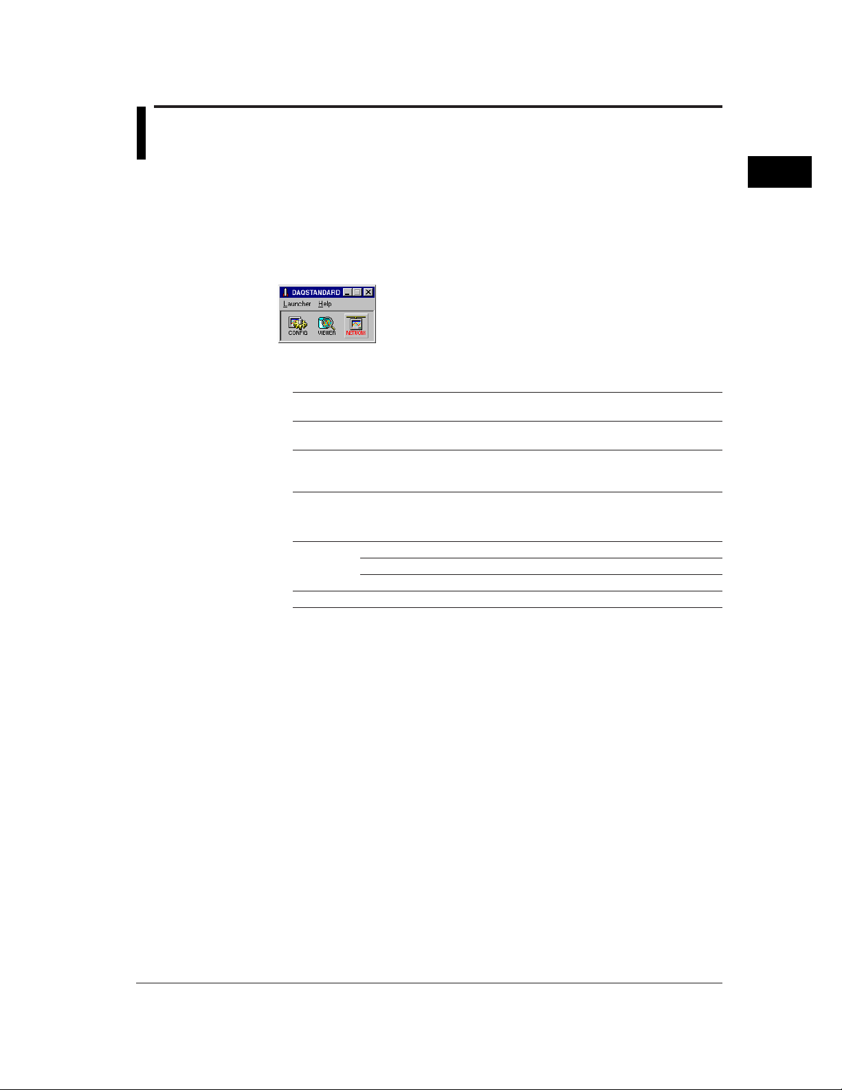
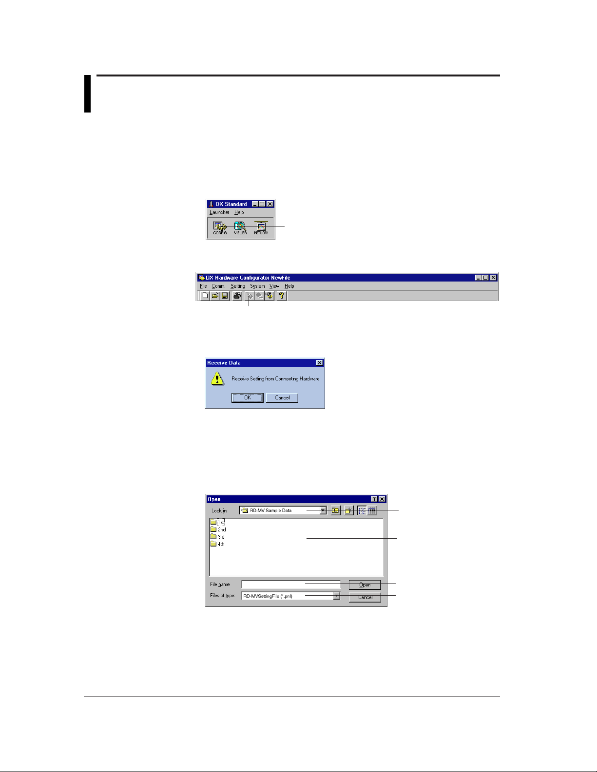
From the Start menu, select [Programs] - [DAQSTANDARD Software] - [Launcher].
Launcher will start, and the following window will appear. If communications have not
been set, the [Network] dialog box will appear. Hardware Configurator (CONFIG), Data
Viewer (VIEWER) and [Network] dialog box (NETWORK) can be started from Launcher.
Description of Each Button
The following three tool buttons are available.
CONFIG Hardware Configurator Start button. Used to start Hardware Configurator. Once
VIEWER Data Viewer Start button. Used to start Data Viewer. Once Data Viewer has
NETWORK [Network] Dialog Box Display button. Used to open the [Network] dialog box to
Description of Each Menu
The following two menus are available.
Launcher Hardware Configurator Same as the CONFIG button
Help About Displays the version number of Launcher.
2
Functions of Launcher
Hardware Configurator has started, this button will be disabled.
started, this button will be disabled.
set communication conditions. Once Hardware Configurator has started, this
button will be disabled.
Data Viewer Same as the VIEWER button
Network Configuration Same as the NETWORK button
2-1
Page 12
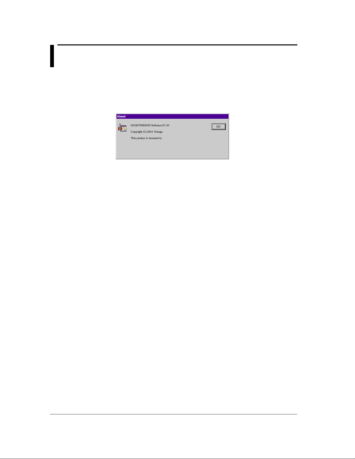
2.2 Displaying the Version Information
To find the version of the DAQSTANDARD Software, display the [About] dialog box.
Operating Method
1. From the menu bar of Launcher, select [Help] - [About].
The [About] dialog box will appear.
2. To close the dialog box, click [OK].
2-2
Page 13
2.3 Setting the Communication Method
Operating Method
Your computer can be communicated with the RD-MV100/RD-MV200 via a network. To
use a network, start Network Configurator and set parameters according to the RDMV100/RD-MV200.
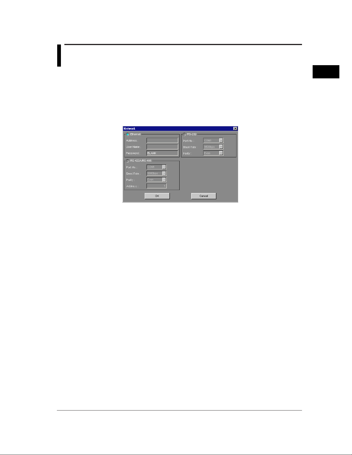
1. Click the CONFIG button of Launcher, or select [Launcher] - [Network Configuration]
from the menu bar. The [Network] dialog box will appear. Ethernet or serial interface
(RS-232 or RS-422A/RS-485) can be used.
2. Select the desired network type. The color of the selected network will turn to blue.
3. Set each parameter. (For a description of the parameters, refer to “Description of
Each Parameter”.)
4. When all the parameters are set, click [OK]. To cancel the settings, click [Cancel].
The dialog will close, and the settings will be reflected to enable communications. (If
communications are in progress, the dialog will close and communications will be restarted.)
2
Functions of Launcher
Description of Each Parameter
Ethernet
Address : Specify the IP address or host name.
User Name : Specify the user name.
Password : Specify the password of the user name.
Serial interface (RS-232 or RS-422A/RS-485)
Port No. : Specify the port no. (COM1 to COM4) to be used.
Baud Rate : Specify the baud rate (2400 to 38400).
Parity : Specify the parity check (None, Odd or Even).
Address : Specify the address (for RS-422A/RS-485 only)
2-3
Page 14
Chapter 3 Hardware Configurator
3.1 Starting Hardware Configurator
Hardware Configurator allows setting of the RD-MV100/RD-MV200 hardware
(measurement/math channels, display method etc.).
Starting Method
Click the [CONFIG] button of Launcher, or select [Launcher] - [Hardware Configurator]
from the menu bar.
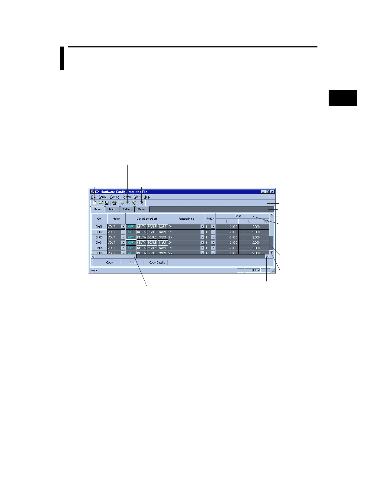
Hardware Configurator Window
The following window will appear when Hardware Configurator is started. (The following
window shows an example of RD-MV200/10CH.)
Data Adjustment button
Send button
Receive button
Print button
Save button
Open button
New button
Scrolls to left when clicked.
Version button
Scrolls to right or left when dragged.
Menu bar
Tool bar
Setting Content tab
Scrolls up when clicked.
Item
Changes when the
[Setting Content]
tab is switched from
one to another.
Scrolls vertically
when dragged.
Scrolls down
when clicked.
Scrolls to right when clicked.
3
Hardware Configurator
3-1
Page 15
3.2 Loading Existing Setup Data
Operating Method
The setup data to be modified can be loaded as follows.
Loading the setup data from the RD-MV100/RD-MV200 currently connected to the
PC
1. Start Hardware Configurator.
Hardware Configurator start button (CONFIG)
2. Click the [Receive] button, or select [Comm.] - [Receive Setting] from the Menu bar.
Receive button
3. A message asking you whether or not to receive the data will appear, so click [OK].
The setup data currently set on the RD-MV100/RD-MV200 will be loaded.
3-2
Loading the setup data from a floppy disk or hard disk
The setup data (.pnl) which has been created on the RD-MV100/RD-MV200 and saved
to a floppy disk or hard disk can be loaded.
1. Start Hardware Configurator.
2. Click the Open button or select [File] - [Open] from the menu bar.
Directory
File list
Selected file
File type
3. From the file list, select the file to be loaded.
4. Click [Open]. The selected file will be loaded.
If the setup data currently edited has not been saved, a message asking you whether
or not to save the data will appear. Click [Yes] if you want to save it, or click [No] if not.
If you want to cancel opening the file, click [Cancel].
Page 16

3.2 Loading Existing Setup Data
Utilizing the default setup data of the DAQSTANDARD Software
1. Start Hardware Configurator.
Hardware Configurator will start with the default settings.
The default settings are as follows:
System RD-MV200, 10CH
Serial interface OFF
Math function ON
External media FDD
Alarm relay 2
Option None
Setup data Default setup data of RD-MV100/RD-MV200 (refer to the RD-
MV100/RD-MV200 manual)
3
Hardware Configurator
3-3
Page 17
3.3 Configuring a New System and Creating Setup
Data
This section explains how to create new setup data without utilizing an existing one. For
this, the configuration of the RD-MV100/RD-MV200 must be specified first.
Operating Method
1. Start Hardware Configurator.
2. Click the New button, or select [File] - [New...] from the menu bar.
If the setup data currently edited has not been saved, a message asking you whether
or not to save the data will appear. Click [Yes] if you want to save it, or click [No] if not.
If you want to cancel creating a new file, click [Cancel].
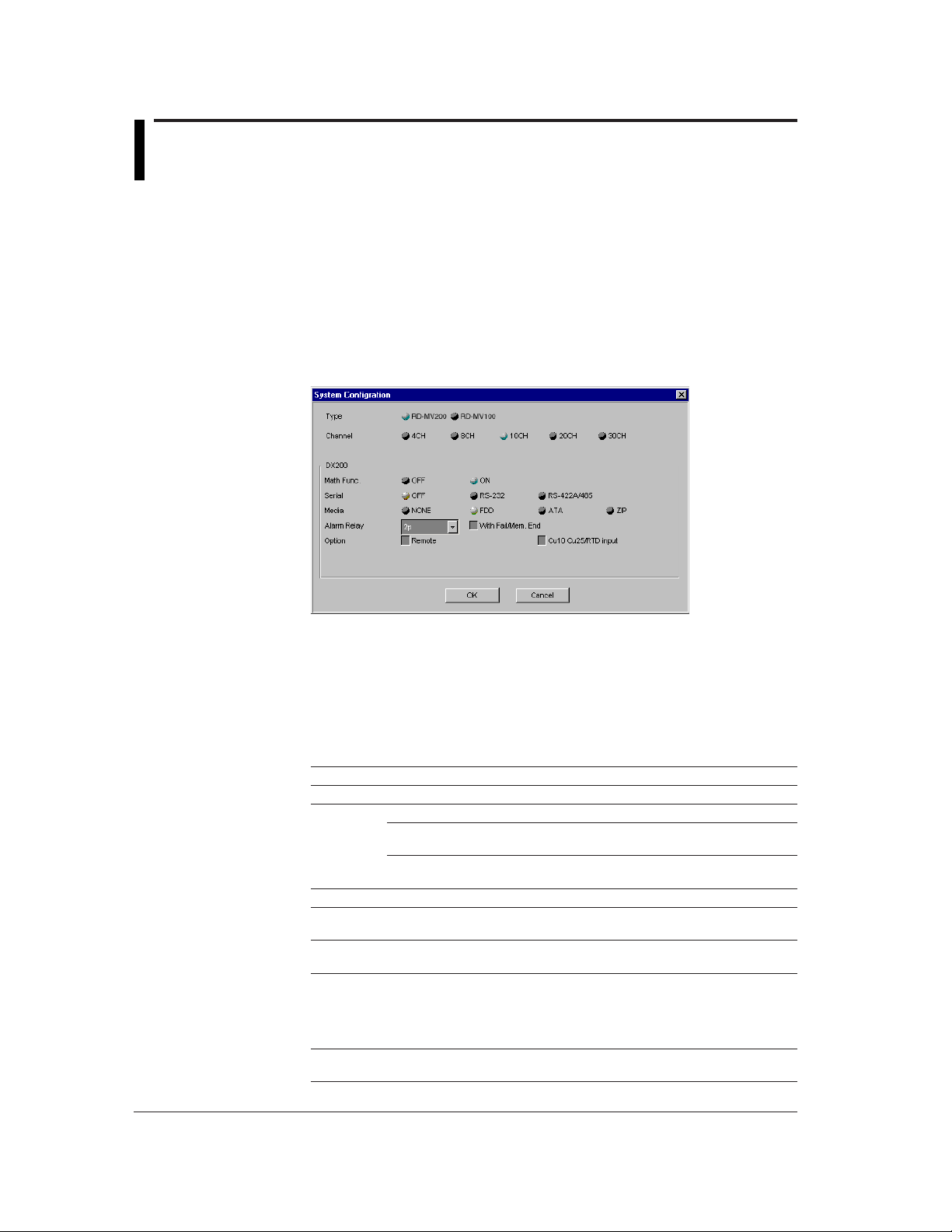
3. If [Yes] or [No] is clicked, the [System Configuration] dialog box will open. Specify the
configuration so that it matches that of the RD-MV100/RD-MV200 to be used.
4. When the configuration has been set, click [OK]. The [System Configuration] dialog
box will close, and the Hardware Configurator window will reappear. Make sure that
the configuration set in the [System Configuration] dialog box is reflected in the
Hardware Configurator window.
To cancel the changes to the configuration, click [Cancel].
5. Proceed to section 3.4.
Description of Each Item
Item Description
Type Select the RD-MV type (RD-MV200 or RD-MV100).
Channel Select the number of channels.
Math Func. Specify whether the RD-MV has a math function.
Serial Select the type of the serial interface to be used from OFF (not used), RS-232C
Media Select the type of external media to be used from NONE (not used), FDD, ATA
Alarm Relay Specify the number of alarm relays to be used. Also specify whether FAIL/
Option Specify whether the remote function is available. Also specify whether Cu10 and
RD-MV200 4CH or 8H for RD-MV204 or RD-MV208, 10CH, 20CH or
30H for RD-MV210, RD-MV220 or RD-MV230
RD-MV100 2CH or 4CH for RD-MV102 or RD-MV104, 6CH or 12CH for
RD-MV106 or RD-MV112
and RS-422.
and ZIP.
memory end output relay is to be used.
The number of alarm relays must be selected from the following:
RD-MV200: NONE (no alarm), 2, 4, 6, 12, 24
RD-MV100: NONE (no alarm), 2, 4, 6
Cu25 are available.
3-4
Page 18
3.4 Overview of Measurement Channels
This section explains how to set items regarding measurement channels.
Operating Method
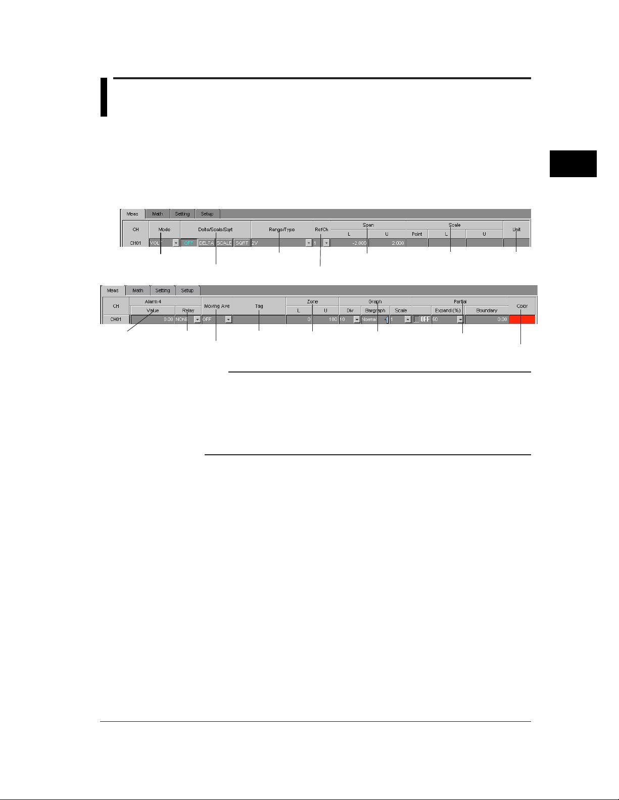
1. Start Hardware Configurator.
2. Click the [Meas] tab, or select [Setting] - [SET [Regular] Setting] - [Meas Channels]
from the menu bar. The following measurement channel page will open.
3. Set each item.
3
Hardware Configurator
Mode (input mode)
Alarm
Alarm output relay
Delta/scale/square
Moving averaging (or filter)
Note
• The [Meas] page is organized in spreadsheet form. Measurement channels are viewed in
rows and items are viewed in columns.
• If the desired channel or item is not shown in the page, enlarge the window size or drag the
vertical (or horizontal) scroll bar until it appears.
• Items can also be set using a dialog box which can be opened for each individual channel (to
open the dialog box, double-click the desired channel no.). For a detailed description, refer to
3.14, "Making Settings for Each Individual Measurement Channel".
Range/type
Tag
Reference channel
Zone
Span
Graph
Scale Unit
Partial expand
Display color
3-5
Page 19
3.5 Setting a Channel to Measure DC Voltage
Click
(VOLT Mode)
This section explains how to set a channel to measure DC voltage.
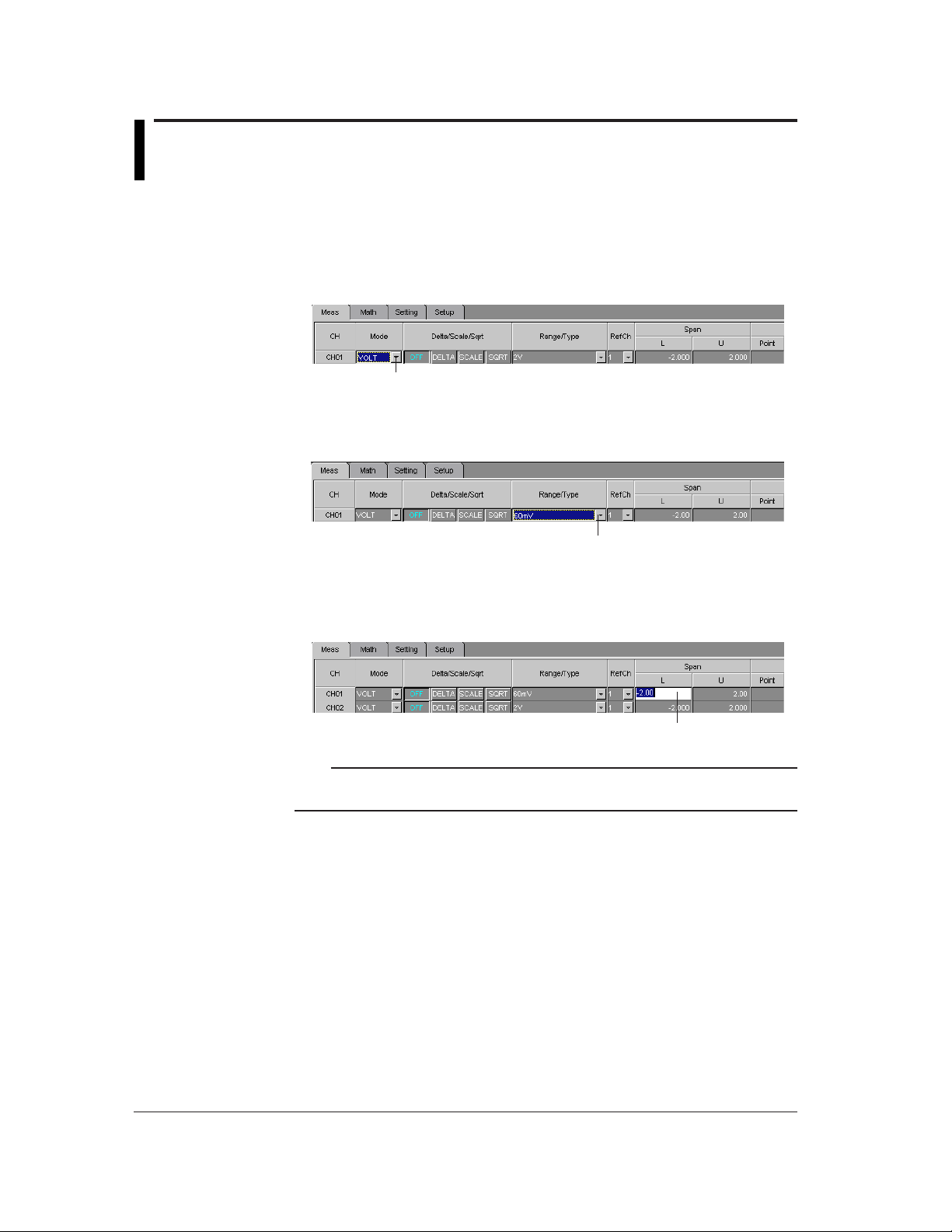
Operating Method
1. Mode
Click the Mode Select button of the target channel. A pull-down menu will appear, so
select [VOLT].
2. Range
3. Span L, Span U
Mode Select button
Click the Range/Type Select button. A pull-down menu will appear, so select the
desired input range.
Range/Type Select button
Click the currently set span L (or span U). It can now be changed, so enter the desired
lower (span L) and upper (span U) limits.
Note
• If a value outside the settable range is entered or if the same value is entered for Span L
and Span U, the value will be corrected when data adjustment is performed.
3-6
Page 20
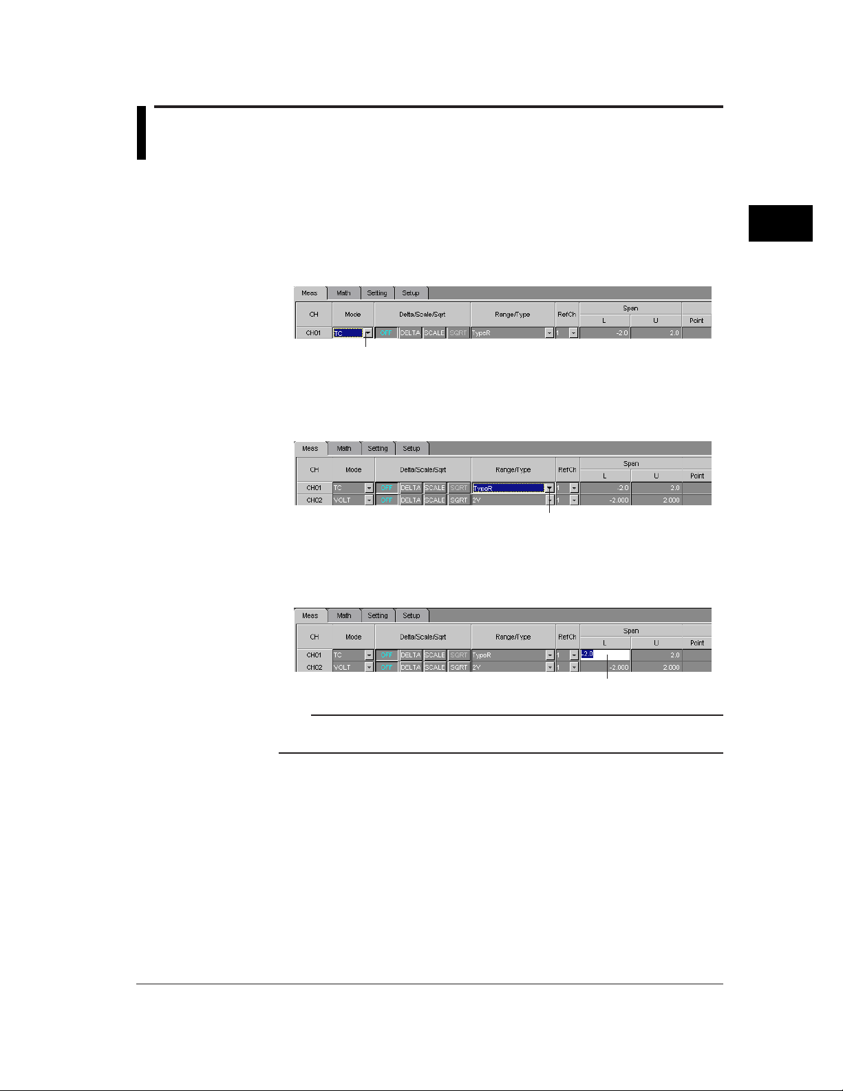
3.6 Setting a Channel to Measure TC/RTD Input
Mode Select button
Range/Type Select button
Click
(TC/RTD Mode)
This section explains how to set a channel to measure the input from a thermocouple
(TC) or resistance temperature detector (RTD).
Operating Method
1. Mode
Click the Mode Select button of the target channel. A pull-down menu will appear, so
select [TC] or [RTD].
2. Type
Click the Range/Type Select button. A pull-down menu will appear, so select the
desired TC or RTD type.
3
Hardware Configurator
3. Span L, Span U
Click the currently set span L (or span U). It can now be changed, so enter the desired
lower (span L) and upper (span U) limits.
Note
• If a value outside the settable range is entered or if the same value is entered for Span L
and Span U, the value will be corrected when data adjustment is performed.
3-7
Page 21
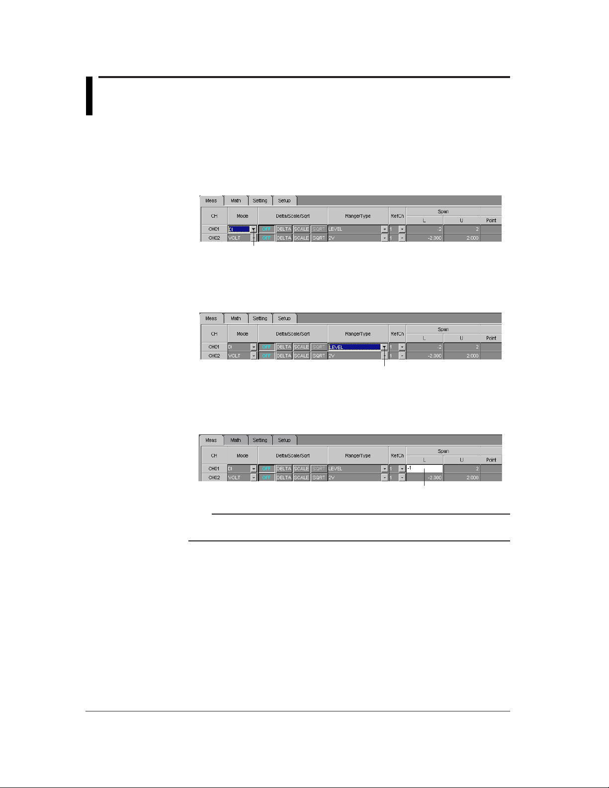
3.7 Setting a Channel to Measure Voltage Level (DI
Mode Select button
Range/Type Select button
Mode)
This section explains how to set a channel to measure voltage level.
Operating Method
1. Mode
Click the Mode Select button of the target channel. A pull-down menu will appear, so
select [DI].
2. Range
Click the Range/Type Select button. A pull-down menu will appear, so select [LEVEL]
(voltage level) or [CONT] (contact).
3. Span L, Span U
Click the currently set span L (or span U). It can now be changed, so enter the desired
lower (span L) and upper (span U) limits.
Click
Note
• If a value outside the settable range is entered or if the same value is entered for Span L
and Span U, the value will be corrected when data adjustment is performed.
3-8
Page 22
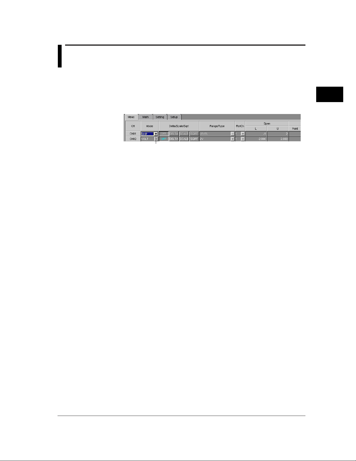
3.8 Setting a Channel to Exclude Measure/Display
Mode Select button
(SKIP Mode)
This section explains how to set a channel so that it does not perform measurement.
Operating Method
1. Mode
Click the Mode Select button of the target channel. A pull-down menu will appear, so
select [SKIP].
Items such as Delta/Scale/Sqrt and Range/Type will be invalidated.
3
Hardware Configurator
3-9
Page 23
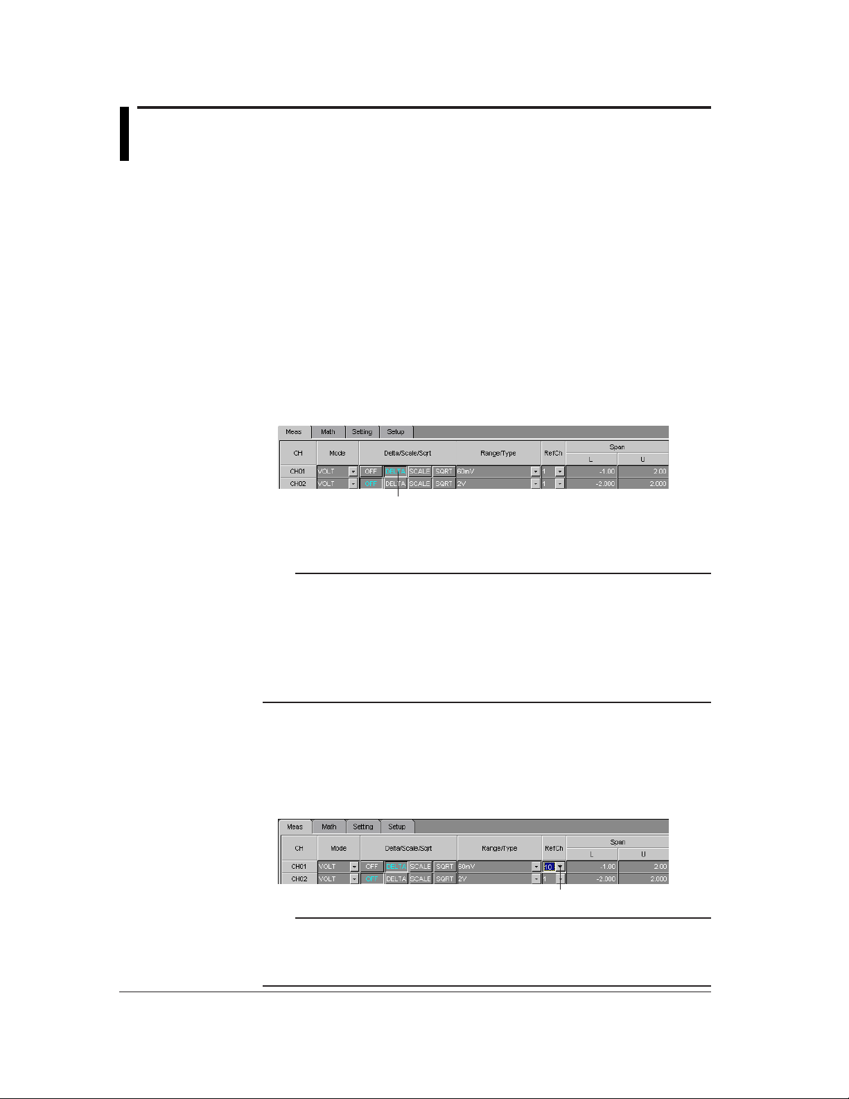
3.9 Setting the Delta Math Function
Click
Reference Channel Select button
This section explains how to set a channel so that it displays the difference in the
measured value from the reference channel. This function is used when VOLT, TC or
RTD is selected as the input mode. (A channel to which Delta is designated is called a
Delta channel.)
(Value measured by the Delta channel) - (Value measured by the reference channel) =
Displayed by the Delta channel
Operating Method
1. Mode
Make sure that [VOLT], [TC] or [RTD] is selected as the input mode for the target
channel.
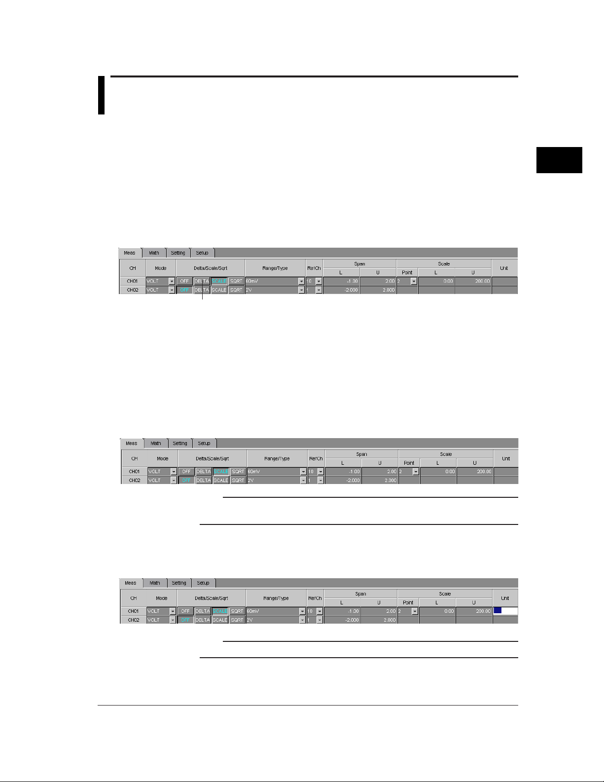
2. Delta/Scale/Sqrt
Click [DELTA] to select it. The color of [DELTA] will switch to blue.
[OFF] is selected as the default.
3. Range
Set an appropriate range/type.
Note
• If Delta is performed between channels having different range/type settings, the position of
the decimal point of the result will be the same as that for the Delta channel. If the number
of decimal places for the reference channel is greater than that for the Delta channel, the
value in the decimal place next to the last decimal place for the Delta channel will be
rounded up.
For instance, if the Delta channel shows 100.0 and reference channel shows 0.050, the
value in the second decimal place for the reference channel will be rounded up (i.e. 0.050
→ 0.1). Thus, the result will be 99.9 (= 100.0 - 0.1).
4. Span L, Span U
Set span L and U.
5. Refch
Click the Reference Channel Select button. A pull-down menu will appear, so select
the channel no. to be used as the reference channel.
Note
• If the reference channel no. is greater than the Delta channel no., the difference between
the value measured by the Delta channel and that measured by the reference channel in
the previous scan will be displayed.
• The selected reference channel will be invalid if Delta is not selected.
3-10
Page 24
3.10 Setting the Scale Math Function
If an input mode other than SKIP is selected, the display scale can be set. This section
explains the method.
Operating Method
1. Mode
Make sure that an input mode other than SKIP is selected for the target channel.
2. Delta/Scale/Sqrt
Click [SCALE] to select it. The color of [SCALE] will switch to blue.
[OFF] is selected as the default.
Click
3. Range
Make sure that an appropriate range/type is selected.
4. Span L, Span U
Make sure that appropriate span L and U are selected.
3
Hardware Configurator
5. Scale L, Scale U, Point
Click the currently set scale L (or scale R). It can now be changed, so enter the
desired lower (scale L) and upper (scale U) limits.
Note
• If a value outside the settable range is entered or if the same value is entered for Scale L
and Scale U, the value will be corrected when data adjustment is performed.
6. Unit
Click the currently set unit. It can now be changed, so enter the desired unit (up to six
characters).
Note
• For characters which can be used for the unit, refer to 3.62, "Usable Characters".
3-11
Page 25
3.11 Setting the Square Math Function
SQUARE can be selected only if VOLT has been selected as the input mode. Selecting
SQUARE will calculate the square root of the input and display the result at the specified
scale.
Operating Method
1. Mode
Make sure that [VOLT] is selected as the input mode for the target channel.
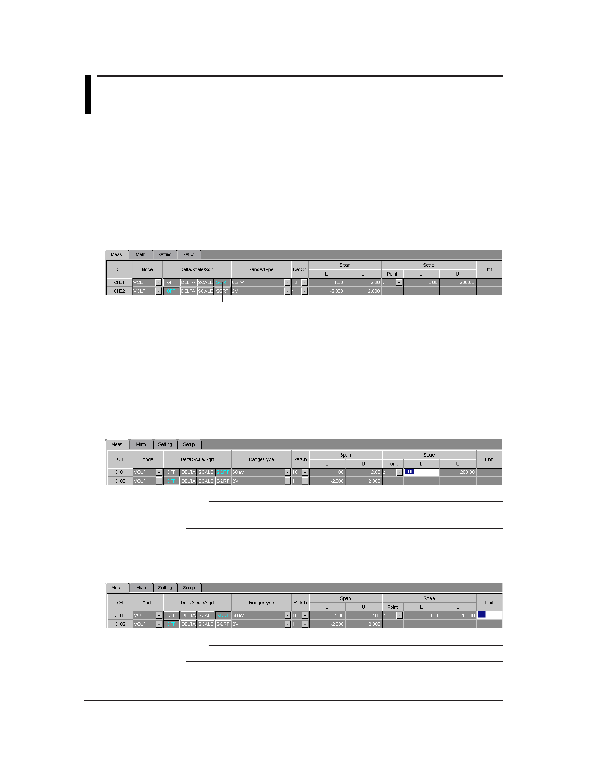
2. Delta/Scale/Sqrt
Click [SQUARE] to select it. The color of [SQUARE] will switch to blue.
[OFF] is selected as the default.
Click
3. Range
Set an appropriate range/type.
4. Span L, Span U
Set appropriate span L and U.
5. Scale L, Scale U, Point
Click the currently set scale L (or scale R). It can now be changed, so enter the
desired lower (scale L) and upper (scale U) limits.
Note
• If a value outside the settable range is entered or if the same value is entered for Scale L
and Scale U, the value will be corrected when data adjustment is performed.
6. Unit
Click the currently set unit. It can now be changed, so enter the desired unit (up to six
characters).
Note
• For characters which can be used for the unit, refer to 3.62, "Usable Characters".
3-12
Page 26
3.12 Setting Alarms to a Measurement Channel
Alarms 1 to 4 can be set for each measurement channel. This section explains how to
set them.
Operating Method
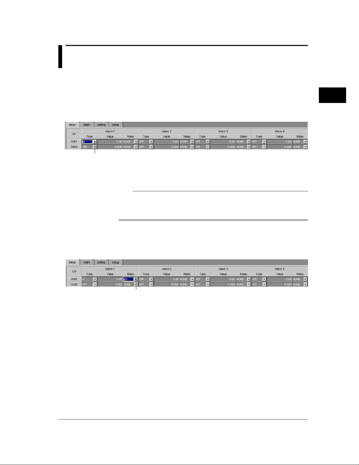
1. Alarm 1: Type
Click the Alarm Type Select button. A pull-down menu will appear, so select the
desired alarm type. If you are not going to set alarm, select [OFF].
Alarm Type Select button
2. Alarm 1: Value
Click the currently set alarm value. It can now be changed, so enter the desired value.
Note
• The settable range for the alarm value will vary with the selected input mode, math
function (Delta/Scale/Sqrt), range/type and alarm type.
• If a value outside the settable range is entered, the value will be corrected when data
adjustment is performed.
3
Hardware Configurator
3. Alarm 1: Relay
Click the Relay Select button. A pull-down menu will appear, so select [NONE] if you
are not going to use any output relays or select the desired output relay no. if you are
going to use one.
Relay Select button
4. If necessary, repeat the above steps to set other alarms (2 to 4).
3-13
Page 27
3.13 Setting the Input Filter/Moving Averaging
An input filter or moving averaging can be set to measurement channels. The input filter
can be set for RD-MV102, RD-MV104, RD-MV204 and RD-MV208 and moving
averaging for RD-MV106, RD-MV112, RD-MV210, RD-MV220 and RD-MV230.
Operating Method
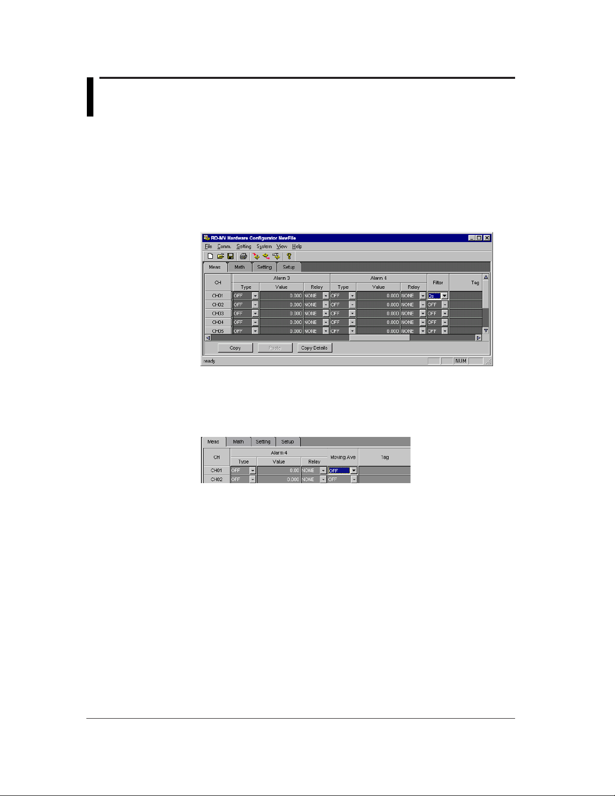
1. Filter
Use to select the desired filter. Select [OFF] if you are not going to use any filters. If
you want to use a filter, select the desired time constant (from 2s, 5s and 10s). [OFF]
is selected as the default.
2. Moving Ave
Select the desired moving averaging times (sampling times). Select [OFF] if you are
not going to use moving averaging. If you want to use it, select the desired sampling
times (2 to 16). [OFF] is selected as the default.
3-14
Page 28
3.14 Making Settings for Each Individual
Measurement Channel
Settings can be made for each individual measurement channel.
Operating Method
1. Double-click the desired channel no.
Double-click
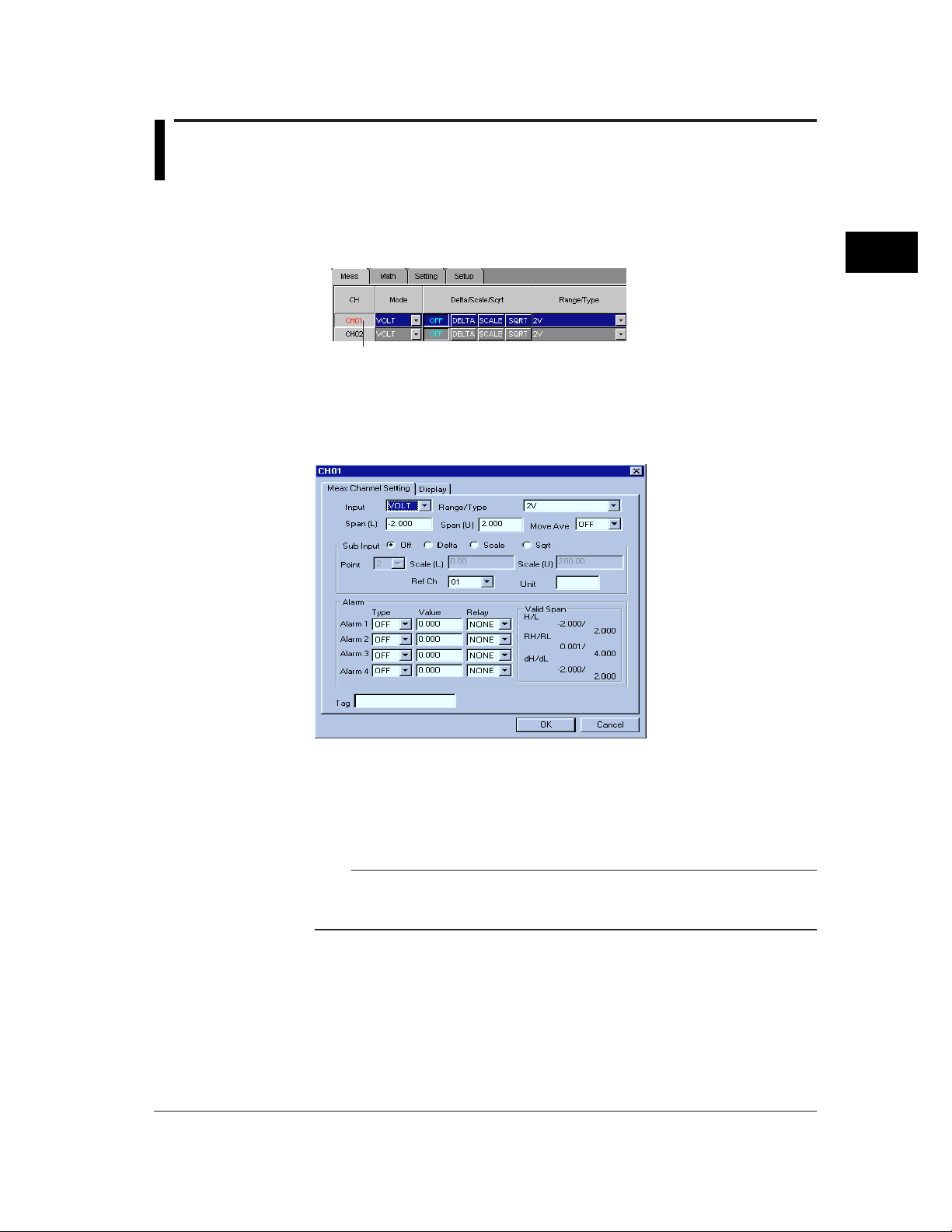
2. The following dialog box will appear. The dialog box consists of two pages: Meas
Channel Setting and Display.
[Meas Channel Setting] Page
3
Hardware Configurator
1. Set each item.
The contents of each item are the same as those in the spreadsheet form, so refer to
the related sections.
2. When all the items are set, click [OK] to close the dialog box.
Note
• The settings made will be reflected in the spreadsheet form.
• If you want to cancel the changes and restore the previous settings, click [Cancel] and
close the dialog box.
3-15
Page 29
3.14 Making Settings for Each Individual Measurement Channel
Item Description Related Sections
Input Select the input mode. 3.5 to 3.8
Range/Type Select the measuring range/type. 3.5 to 3.8
Span (L), Span (U) Set the lower and upper limits of the span. 3.5 to 3.8
Move Ave Set the sampling times (this item is displayed 3.13
Filter Set the filter (this item is displayed only 3.13
Sub Input Select the math function to be used. 3.9 to 3.11
Point, Scale (L), Scale (U)
Ref Ch Select the reference channel. 3.9
Unit Set the unit if SCALE or SQRT is selected. 3.10, 3.11
Alarm Set the alarms. 3.12
Tag Set the tag name. 3.23
only for medium-speed type).
for high-speed type).
Set the display scale. 3.10, 3.11
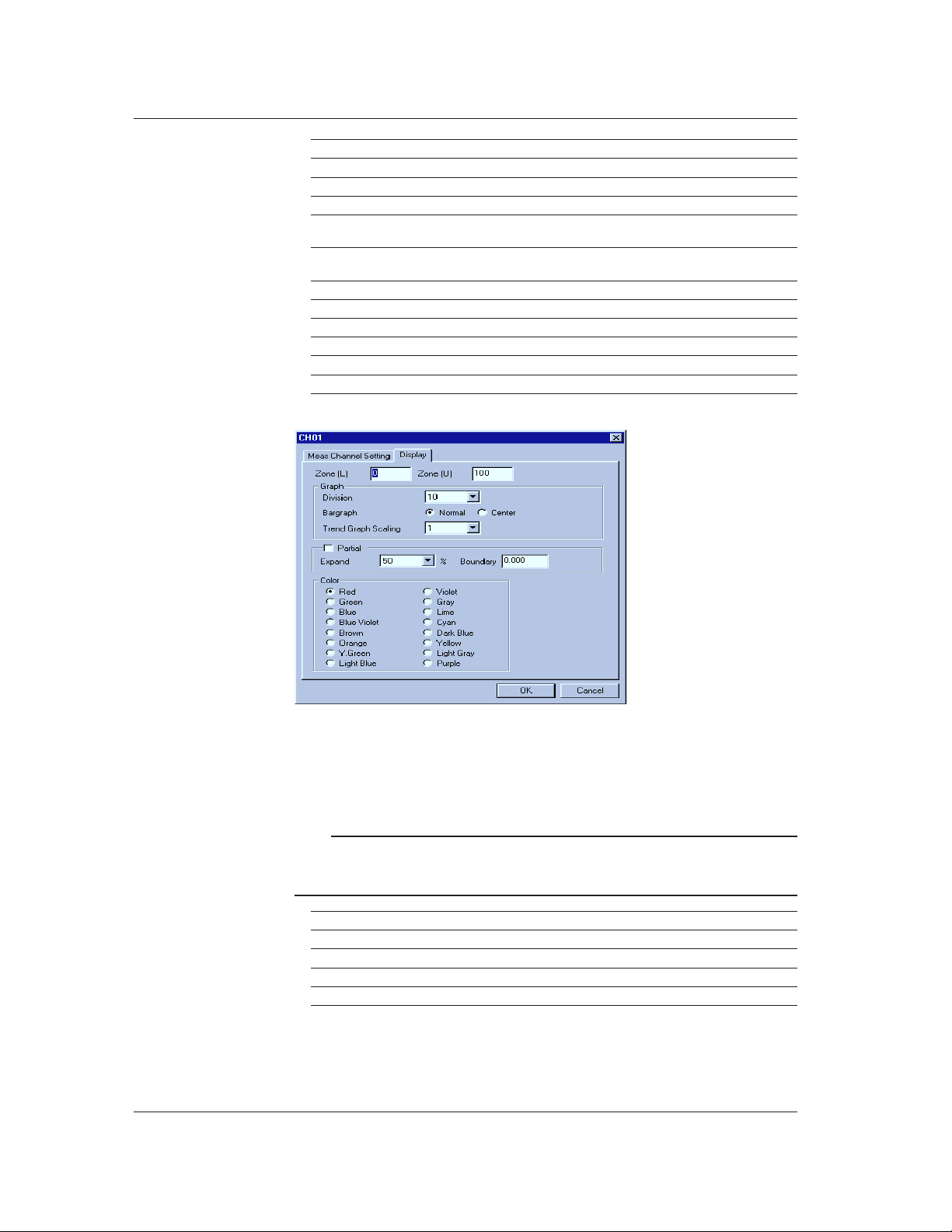
[Display] Page
3-16
1. Set each item.
The contents of each item are the same as those in the spreadsheet form, so refer to
the related sections.
2. When all the items are set, click [OK] to close the dialog box.
Note
• The settings made will be reflected in the spreadsheet form.
• If you want to cancel the changes and restore the previous settings, click [Cancel] and
close the dialog box.
Item Description Related Sections
Zone (L), Zone (U) Set the display zone. 3.30
Graph Set the bar graph. 3.31
Partial Set the partial expand function. 3.32
Color Select the display color. 3.29
Page 30
3.15 Overview of Math Channels
It is possible to specify an expression which uses the measured data as a variable, and
display or save the math results. An expression can be set for each math channel.
Operating Method
1. Start Hardware Configurator.
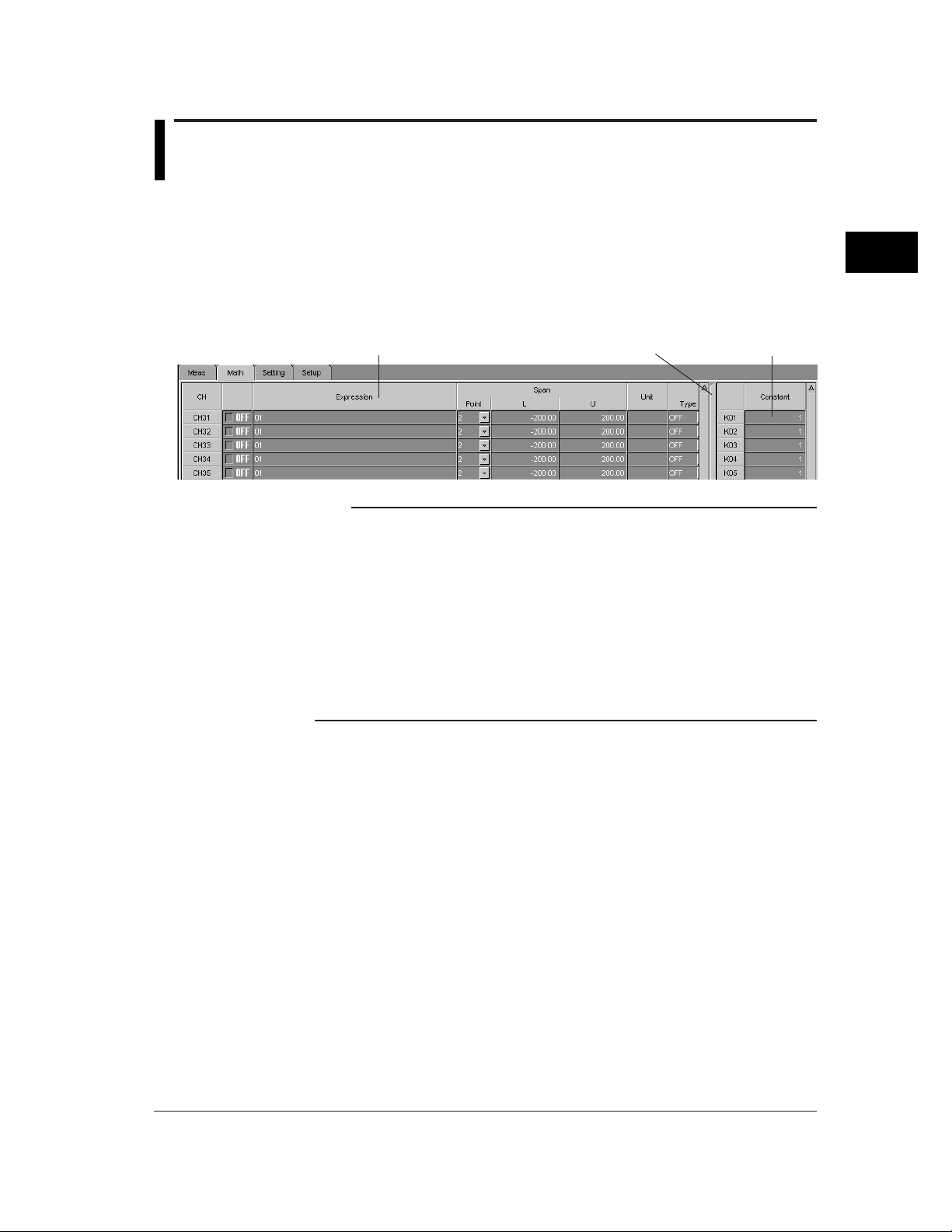
2. Click the [Math] tab, or select [Setting] - [SET [Regular] Setting] - [Math Functions]
from the menu bar. The following math channel page will open.
3. Set each item.
3
Hardware Configurator
Expression setting section
Separator
Constant setting section
Note
• The [Math] page consists of the expression setting and constant setting sections. They are
separated by the separator bar.
• Each time the separator bar is clicked, the constant setting section appears and
disappears alternately.
• The expression setting section is organized in a spreadsheet form. Math channels are
viewed in rows and items are viewed in columns. The constant setting section have
constants (K01 to K30) in rows.
• If the desired channel or item is not shown in the page, enlarge the window size or drag
the vertical (or horizontal) scroll bar until it appears.
• Items can also be set using a dialog box which can be opened for each individual channel
(to open the dialog box, double-click the desired channel no.). For a detailed description,
refer to 3.21, "Making Settings for Each Individual Math Channel".
3-17
Page 31

3.16 Setting a Math Channel
It is possible to set an expression, span and unit and whether the expression is to be
used. This setting can be made for each math channel.
Operating Method
1. ON/OFF
Set whether the expression set at step 2 is to be used or not. Select [ON] if you are
going to use it, or select [OFF] if not.
2. Expression
Specify the desired expression (up to 40 characters). Click the currently specified
expression. It can now be changed, so specify the desired expression. The
expression can consist of measurement/math channel nos., constant nos. (K01 to
K30) and various operators.
For details on expression, refer to the RD-MV100 or RD-MV200 manual.
Note
• A method that allows you to select operators just by selecting them from a list is also
available. For details, refer to 3.21, "Making Settings for Each Individual Math Channel".
3. Span L, Span U
Set the lower (span L) and upper (span U) limits of the display span. Click the
currently set span L (or span U). It can now be changed, so enter the desired lower
(span L) and upper (span U) limits.
Note
• Settable range: -9999999 to 99999999
• The number of decimal places must be 4 or less.
• If a value outside the settable range is entered or if the same value is entered for Span L
and Span U, the value will be corrected when data adjustment is performed.
4. Unit
Used to specify the unit to be used for the math channel. Click the currently set unit. It
can now be changed, so enter the desired unit (up to six characters).
Note
• For characters which can be used for the unit, refer to 3.62, "Usable Characters".
3-18
Page 32

3.17 Setting Alarms to a Math Channel
Alarms 1 to 4 can be set for each math channel. This section explains how to set them.
Operating Method
1. Alarm 1: Type
Click the Alarm Type Select button. A pull-down menu will appear, so select the
desired alarm type. If you are not going to set alarm, select [OFF].
Alarm Type Select button
2. Alarm 1: Value
Click the currently set alarm value. It can now be changed, so enter the desired value.
Note
• The settable range is from span L to span U.
• If a value outside the settable range is entered, the value will be corrected when data
adjustment is performed.
3. Alarm 1: Relay
Click the Relay Select button. A pull-down menu will appear, so select [NONE] if you
are not going to use any output relays or select the desired output relay no. if you are
going to use one.
3
Hardware Configurator
Relay Select button
4. If necessary, repeat the above steps to set other alarms (2 to 4).
3-19
Page 33

3.18 Setting the TLOG Math Function (Setting the
Timer/Sum Scale)
This section explains how to set the timer to be used for a math channel to which TLOG
is designated. The sum scale to be used for TLOG.SUM.
Operating Method
1. Timer
Select the desired timer from timers 1 to 3 set in setup mode.
Click the Timer Select button. A pull-down menu will appear, so select the desired
timer no. The time set on the selected timer will be the math interval for TLOG.SUM.
2. Sum Scale
Used to select the desired sum scale. Click the Sum Scale Select button. A pull-down
menu will appear, so select the desired sum scale.
3-20
Page 34

3.19 Setting the Rolling Averaging Function
It is possible to set whether the math result is to be subjected to rolling averaging. This
setting can be made for each math channel.
Operating Method
1. ON/OFF
Set whether rolling averaging is to be used or not. Select [ON] if you are going to use
it, or select [OFF] if not.
2. Interval
Used to set the data collection interval (sampling interval) for rolling averaging. Click
the Interval Select button. A pull-down menu will appear, so select the desired
sampling interval.
3. Times
Used to set the number of data sets (sampling times) to be subjected to rolling
averaging. Click the Times Select button. A pull-down menu will appear, so select the
desired sampling times.
3
Hardware Configurator
3-21
Page 35

3.20 Setting a Constant
It is possible to set constants to be used for the expression.
Operating Method
1. Constant
Used to set a constant. Click the currently set constant. It can now be changed, so
enter the desired constant.
Note
• Up to 30 constants (K01 to K30) can be set.
• Constants can be specified using an exponent (e.g. 1.00E+19). For details, refer to the
RD-MV100/RD-MV200 manual.
3-22
Page 36

3.21 Making Settings for Each Individual Math
Double-click
Channel
Settings can be made for each individual math channel.
Operating Method
1. Double-click the desired channel no.
2. The following dialog box will appear. The dialog box consists of two pages: Math
Channel Setting and Display.
[Math Channel Setting] Page
3
Hardware Configurator
1. Set each item.
The contents of each item are the same as those in the spreadsheet form, so refer to
the related sections.
2. When all the items are set, click [OK] to close the dialog box.
Note
• Clicking [Operator] will display the [Select Operator] dialog box. This allows you to specify
an operator just by selecting it from the list.
3-23
Page 37

3.21 Making Settings for Each Individual Math Channel
Note
• The settings made will be reflected in the spreadsheet form.
• If you want to cancel the changes and restore the previous settings, click [Cancel] and
close the dialog box.
Item Description
Function Select whether the math function is to be used or not.
Expression Specify the desired expression (up to 40 characters).
Operator Clicking [Operator] will display a list of operators. Select the desired
Point, Span (L), Span (U) Set the lower and upper limits of display span.
Unit Set the unit to be used for the math channel.
Rolling Average Set the sampling interval and times.
Alarm Set the alarms.
Tag Set the tag name.
TLOG Timer Select a timer from timers 1 to 3 set in setup mode.
Sum Scale Set the sum scale.
[Display] Page
operator from the list.
3-24
Same as that for measurement channels. Refer to 3.14, "Making Settings for Each
Individual Measurement Channel".
Page 38

3.22 Copying the Settings From one Channel to
Another
The settings made to one channel can be copied to another channel. The method is
basically the same, irrespective of measurement or math channels.
Operating Method
1. Click the source channel no. The row of the selected channel will be highlighted, and
the color of the channel no. will switch to red.
Note
• If you want to copy the settings of two or more channels, select the corresponding channel
nos. by dragging them
2. Click [Copy Details]. The [Meas Channel Copy Details] dialog box will open. (In the
case of math channels, the [Math Channel Copy Details] dialog box will open.)
3
Hardware Configurator
3. Select the item(s) to be copied, and then click [OK]. To select all the items, click
[Select All]. The dialog box will close.
4. Click [Copy]. Selection of the source channels and items will be confirmed.
5. Click the destination channel no. The row of the selected channel will be highlighted,
and the color of the channel no. will switch to red.
Note
• If you want to copy the settings to two or more channels, select the corresponding channel
nos. by dragging them
6. Click [Paste]. The settings will be copied.
3-25
Page 39

3.23 Assigning a Tag Name to a Channel
A tag name can be assigned to a channel and displayed instead of the channel no. The
method is the same, irrespective of measurement or math channel.
Selection of whether the channel nos. or tag names are to be displayed can be made in
setup mode (refer to 3.42, "Selecting to Display Tag Names or Channel Nos.".
Operating Method
1. Tag
Click the currently set tag name. It can now be changed, so enter the desired tag
name.
Note
• The tag name can consist of up to 16 characters. For characters which can be used for
the unit, refer to 3.62, "Usable Characters".
• If no tag name is assigned even though a setting has been made so that the tag name
would be displayed, the channel no. will be displayed.
• The same setting method will also apply to math channels.
3-26
Page 40

3.24 Assigning a Channel to a Group
Measurement/math channels can be assigned to groups.
Operating Method
1. Displaying the menu
Click the [Setting] tab and select [Group/Trip Line], or select [Setting] - [SET [Regular]
Setting] - [Group] from the menu bar.
3
Hardware Configurator
2. Group number
Click the tab of the desired group no. (in the above example, group 1 is selected).
3. Group Name
Click the currently set group name. It can now be changed, so enter the desired group
name.
Note
• The group name can consist of up to 16 characters. For characters which can be used for
the unit, refer to 3.62, "Usable Characters".
4. Meas/Math
Click the channel(s) to be assigned to the selected group. The color of the selected
channels will switch to blue.
Note
• Up to 10 channels can be assigned to each group in the case of RD-MV200 (6 channels in
the case of RD-MV100).
• The assigned channels will be displayed under Channel Configuration.
• If no channels are assigned, CH01 will be assigned automatically.
3-27
Page 41

3.25 Assigning Display Contents to a View Group
(RD-MV200 Only)
The view type (i.e. the contents to be displayed) can be assigned to each group. Seven
view kinds are available (e.g. trend display, digital display, bar graph).
Operating Method
1. Displaying the menu
Click the [Setting] tab and select [View Group], or select [Setting] - [SET [Regular]
Setting] - [View Group] from the menu bar.
2. View Group 1/2/3/4
Click the tab of the desired view group no. (in the above example, view group 1 is
selected).
3. Group Name
Click the currently set view group name. It can now be changed, so enter the desired
view group name.
Note
• The view group name can consist of up to 16 characters. For characters which can be
used for the unit, refer to 3.62, "Usable Characters".
4. View Kind
Used to select a view kind for each view (each view group can have four views). Click
the button in the combo box. A list of view kinds will appear, so select the desired view
kind.
The selected view kind will be displayed graphically next to View Kind.
5. Group
Select the group to be displayed in each view. The color of the selected group will
switch to blue.
3-28
Page 42

3.26 Setting Trip Lines
For trend display, trip lines can be displayed to indicate target positions on the scale. Up
to four trip lines can be set for each group.
Operating Method
1. Displaying the menu
Click the [Setting] tab and select [Group/Trip Line], or select [Setting] - [SET [Regular]
Setting] - [Trip Line] from the menu bar.
2. Group 1/2/3/4
Click the tab of the desired group no. (in the above example, group 1 is selected).
3. Trip Line
Use to select trip lines to be displayed. Select [ON] if you want to display the trip line,
or select [OFF] if not.
4. Display position (slider)
Used to set the display position of the trip line as the position (%) on the display scale.
The position can be set by dragging the slider to right/left or by entering the desired
value (%).
5. Color
The currently selected color is displayed in the [Color...] button. To change the color,
click the button.
The [Color] dialog box will appear, so select the desired color and click [OK]. The
selected color will appear in the button.
3
Hardware Configurator
Note
• A color can be selected from a total of 16 colors.
• To cancel change and restore the previously selected color, click [Cancel].
6. Repeat steps 3 to 5 to set other trip lines.
3-29
Page 43

3.27 Setting the Display Update Interval
The time per division for the trend display time axis can be set.
Operating Method
1. Displaying the menu
Click the [Setting] tab and select [Display], or select [Setting] - [SET [Regular] Setting]
- [Trend/Save Interval] from the menu bar.
2. Display Update Interval
Set the time per division.
3-30
Page 44

3.28 Entering a Message
Messages can be set and displayed in trend display or saved together with the display/
event data. Up to eight messages can be set.
Operating Method
1. Displaying the menu
Click the [Setting] tab and select [Message/File], or select [Setting] - [SET [Regular]
Setting] - [Message] from the menu bar.
2. Message
Click the message display area of the desired message no. The currently set
message can now be changed, so enter the desired message.
3
Hardware Configurator
Click
Note
• Messages can consist of up to 16 characters. For characters which can be used for the
unit, refer to 3.62, "Usable Characters".
3. To set a message for other message nos., repeat step 2.
Copying a Message
The message set to a message no. can be copied to another message no.
1. Click the source message no. The color of the message no. will switch to red.
Note
• If you want to copy two or more messages, select the corresponding message nos. by
dragging them
2. Click [Copy].
3. Click the destination message no. The color of the selected message no. will switch to
red.
Note
• If you want to copy the message to two or more message nos., select the corresponding
channel nos. by dragging them
4. Click [Paste].
The message will be copied.
3-31
Page 45

3.29 Setting the Display Color
The display color can be set for each channel. The method is the same, irrespective of
measurement or math channel.
Operating Method
1. Displaying the [Color] dialog box
Click the currently selected color of the desired channel.
The [Color] dialog box will appear.
2. Selecting a color
Select the desired color and click [OK].
The selected color will appear.
Note
• A color can be selected from a total of 16 colors.
• To cancel change and restore the previously selected color, click [Cancel].
3-32
Page 46

3.30 Setting the Display Zone
By setting the display zone, waveforms can be displayed in different areas of the
window. This avoids overlapping of waveforms, making them easier to view. The
waveforms are displayed between the specified upper and lower limits of the display
zone. The setting method is the same, irrespective of measurement or math channels.
Operating Method
1. Click the [Meas] (or [Math] tab).
2. L
Click the currently set lower limit. It can now be changed, so enter the desired lower
limit.
3. U
Click the currently set upper limit. It can now be changed, so enter the desired upper
limit.
Note
• Both lower and upper limits must be set in percentage (%) of the display scale.
• The settable range of the zone is given below.
Settable range: 0% to 100%
Lower limit < Upper limit
The difference between the lower and upper limits: 5 or more
• If a value outside the settable range entered, the value will be corrected when data
adjustment is performed.
3
Hardware Configurator
3-33
Page 47

3.31 Setting the Graph Properties
It is possible to set the number of divisions of graph, reference position of the bar graph
and scale of the trend graph. The setting method is the same, irrespective of
measurement or math channels.
Operating Method
1. Click the [Meas] (or [Math] tab).
2. Div
Set the number of divisions of the display scale. The scale will be equally divided, and
a mark will appear at each division position. A value between 4 and 12 can be
selected (default: 10).
3. Bargraph
Used to set the reference position of the bar graph. Normal or Center can be selected.
Note
• If the bar graph is set to be displayed vertically, selection of Center will be ignored.
Normal will be selected when data adjustment is performed.
4. Scale
Used to set the scale display for trend graph. Select OFF or 1 to 10 for RD-MV200,
and OFF or 1 to 6 for RD-MV100.
3-34
Page 48

3.32 Setting the Partial Expand Function
The partial expand function allows you to enlarge the desired part of the waveform along
the axis of measured values (i.e. the remaining part is compressed). The setting method
is the same, irrespective of measurement or math channels. However, for a math
channel, this function will disabled if the channel is set to ignore use of the math function.
Operating Method
1. Click the [Meas] (or [Math] tab).
2. ON/OFF
Used to select whether the partial expand function is to be used or not. Select [ON] if
you are going to use it, or select [OFF] if not.
3. Expand (%)
Used to set the position of the boundary. Set it in relation to the display scale. A value
from 1% to 99% can be set.
4. Boundary
Used to set the display range. By moving to another position within the display range
(step 3), the areas before and after the boundary will be expanded or compressed.
3
Hardware Configurator
Note
• Boundary setting conditions (for measurement channels)
When neither SCALE nor SQRT is selected : Span L < Boundary < Span U
When SCALE or SQRT is selected : Scale L < Boundary < Scale U
• Boundary setting conditions (for math channel)
Span L < Boundary < Span U
• To enable this function, [Partial] must be set to [Use] in the setup mode (refer to 3.43,
"Selecting Whether or Not to Use the Partial Expand Function").
• This setting cannot be made if DI is selected as the input mode.
• If the settings are incorrect, they will be corrected automatically when data adjustment is
performed.
3-35
Page 49

3.33 Setting the Display Direction, Background
Color, Trend/Trip Line Width and Grid
Trend or bar graphs can be displayed vertically or horizontally, and the screen's
background color can be set to white or black. Furthermore, trend/trip line width can be
changed and the grid in the trend display area can be divided between 4 and 12.
Operating Method
1. Displaying the menu
Click the [Setting] tab and select [Display], or select [Setting] - [SET [Regular] Setting]
- [Trend/Bar Direction] from the menu bar.
2. Trend Graph Direction
Select the desired direction. The color of the arrow will switch to blue if [Horizontal] is
selected, or it will switch to red if [Vertical] selected.
3. Bar Graph Direction
Select the desired direction. The color of the arrow will switch to blue if [Horizontal] is
selected, or it will switch to red if [Vertical] selected.
4. Background Color
Select the desired background color.
5. Trend Line Width
Three widths (1, 2, 3) are available for trend lines (the larger, the thicker). Select the
desired width by clicking the corresponding number. The color of the selected width
will switch to blue.
6. Trip Line Width
Three widths (1, 2, 3) are available for trip lines (the larger, the thicker). Select the
desired width by clicking the corresponding number. The color of the selected width
will switch to blue.
7. Grid Division
Used to set the number of grid divisions. Click the button in the combo box. A list will
appear, so select the desired number (4 to 12).
3-36
Page 50

3.34 Setting the LCD Brightness and Saver
Function
The screen brightness and saver function can be set. If the saver function is enabled
(ON), the screen will become blank if no key is pressed or no alarm occurs during the
specified save time.
Operating Method
1. Displaying the menu
Click the [Setting] tab and select [Display], or select [Setting] - [SET [Regular] Setting]
- [LCD Brightness] or [View Saver] from the menu bar.
3
Hardware Configurator
2. LCD Brightness
Used to set the brightness of the LCD screen. Click the button in the list box. A list will
appear, so select the desired brightness (the larger, the brighter). (Brightness levels 1
to 4 are available for RD-MV200, and 1 to 8 for RD-MV100.)
3. Backlight Saver
Used to select whether the saver function is to be used or not. Select [ON] if you are
going to use it, or select [OFF] if not.
4. Saver Time
Used to set the saver time. If no key is pressed or no alarm occurs during the saver
time, the screen will automatically become blank.
The color of the selected time will switch to blue.
5. Restore
Used to set the conditions which cause the screen to restore (i.e. display the
contents). Select [KEY] if you want the screen to restore when a key is pressed, or
select [KEY+ALARM] if you want the screen to restore when a key is pressed or an
alarm occurs.
3-37
Page 51

3.35 Setting the Daylight Saving Time
This section explains how to set summer/winter time.
Operating Method
1. Displaying the menu
Click the [Setting] tab and select [Daylight Saving], or select [Setting] – [SET
[Regular] Setting] – [Daylight Saving] from the menu bar.
2. Summer/Winter
Used to set the summer or winter time. Click the check box on the left of the desired
item (Summer or Winter). The selected check box will switch to blue.
3. Setting the year/month/day/time
Click the currently set year, month, day or time to be changed. It can now be
changed, so enter the desired year, month, day or time.
Note
• Year 2038 and later cannot be set.
3-38
Page 52

3.36 Setting the Alarm Method
This section explains how to set the alarm method.
Operating Method
1. Displaying the menu
Click the [Setup] tab and select [Alarm/Relay/Remote], or select [Setting] - [SET
[Basic] Setting] - [Setting] - [Alarm] from the menu bar.
2. Reflash
Used to select whether reflash alarms are to be used for alarm output relays. Select
[ON] if you are going to use, or select [OFF] if not.
3. Relay AND
Used to select the range of the alarm output relays to be used in AND mode. Select
the last relay of the range. The relays from the first one to the one selected here will
be used in AND mode. The other relays will be used in OR mode. To use all the
relays in OR mode, select [NONE].
3
Hardware Configurator
4. Relay Action
Select whether alarm output relays are to be energized (Energize) or de-energized
(Re-energize) in case of an alarm. The color of the selected option will switch to blue.
5. Alarm Relay Behavior
Select whether alarm output relays are to hold the status (Hold) or not (Unhold). The
color of the selected option will switch to blue.
6. Alarm Indicator
Select whether alarm indication is to be held (Hold) or not (Unhold) even if the alarm
has been cleared. The color of the selected option will switch to blue.
7. Rate of Change Increase
Used to set the interval for upper change rate alarms. Select the desired interval (1 to
15).
8. Rate of Change Decrease
Used to set the interval for lower change rate alarms. Select the desired interval (1 to
15).
9. Alarm Hysteresis
Used to provide a hysteresis between the value which causes an alarm to occur and
the one which causes it to clear. Select [ON] if you want to provide a hysteresis, or
select [OFF] if not. The color of the selected option will switch to blue.
3-39
Page 53

3.37 Setting the Scan Interval
This section explains how to set the scan interval and A/D integration time.
Operating Method
1. Displaying the menu
Click the [Setup] tab and select [Scan Interval/Memory], or select [Setting] - [SET
[Basic] Setting] - [Setting] - [Interval] from the menu bar.
2. Scan Interval
Set the scan interval. The color of the selected scan interval will switch to blue.
Note
• The available scan intervals differ between the medium-speed and high-speed types.
RD-MV102, RD-MV104, RD-MV204, RD-MV208 : 1s, 2s
RD-MV106, RD-MV112, RD-MV210, RD-MV220, RD-MV230 : 125ms,
250ms
3. A/D Integrate
Set the A/D integration time. The color of the selected A/D/D integration time will
switch to blue.
Note
• A/D integration time 100ms can be selected only when 2s is selected for the scan interval.
3-40
Page 54

3.38 Selecting the Burn-out and RJC
This section explains the method for setting how the measurement result is to be treated
in case of a burnout of the thermo-couple in TC input mode. It also explains how to set
the RJC type (internal or external).
Operating Method
1. Displaying the menu
Click the [Setup] tab and select [Channel], or select [Setting] - [SET [Basic] Setting] [Setting] - [Burnout] from the menu bar.
3
Hardware Configurator
2. BURN OUT
Used to select how the measurement result is to be treated in case of a burnout of the
thermo-couple. Select [OFF], [UP] (+ over) or [DOWN] (- over).
3. RJC Type
Used to select the RJC type. Select Internal or External.
4. RJC Volt (uV)
Used to specify the compensation value if [External] is selected as the RJC type.
Enter the desired value (-20,000 to 20,000).
3-41
Page 55

3.38 Selecting the Burn-out and RJC
Copying the Settings
The burnout and RJC settings made to a channel can be copied to another channel.
Operating Method
1. Click the source channel no. The color of the channel no. will switch to red.
Note
• If you want to copy the settings of two or more channels, select the corresponding channel
nos. by dragging them
2. Click [Copy Details].
3. Select the item(s) to be copied, and then click [OK].
4. Click [Copy].
5. Click the destination channel no. The color of the channel no. will switch to red.
Note
• If you want to copy the settings to two or more channels, select the corresponding channel
nos. by dragging them
6. Click [Paste].
The settings will be copied.
3-42
Page 56

3.39 Setting the Save Method for Measurement/
Math Data
This section explains how to set the save method for measurement/math data.
Operating Method
1. Displaying the menu
Click the [Setup] tab and select [Scan Interval/Memory], or select [Setting] - [SET
[Basic] Setting] - [Setting] - [Memory Sample] from the menu bar.
2. Media Save
Used to set whether the data is to be saved manually or automatically. Select [Auto] if
you want to save it automatically, and select [Manual] if you want to save it manually.
3
Hardware Configurator
3. Data
Used to set the type of data to be saved. Select [DISPLAY] if you want to save display
data only, select [EVENT] if you want to save event data only, or select [EVENT &
DISP] if you want to save both.
Note
Steps 4 to 10 are necessary only if [EVENT] or [EVENT & DISP] is selected at step 3, since
they relate to event data.
4. Event Data Sampling Rate
Set the sampling rate for event data. The sampling rate differs between high-speed
and medium-speed types.
5. Event Data Sampling Mode
Used to select the sampling mode. Select from [FREE], [TRIGGER] and [ROTATE].
3-43
Page 57

3.39 Setting the Save Method for Measurement/Math Data
6. Block
Used to divide the event data save area (memory) into blocks. Select the desired
number of blocks from "1" (does not divide), "2", "4", "8" and "16".
Note
The number of blocks can be selected only from "1", "2" and "4" if [EVENT & DISP] is
selected as the data type at step 3.
7. Data Length
Used to set the length (i.e. size) of the event data file. The size must be set in terms of
sampling time. The size varies with the specified event data sampling rate and
number of blocks.
8. Pre-Trigger Length
Used to set the portion of the data to be written before generation of a trigger. The
portion must be set in ratio (0, 5, 25, 50, 75, 95 and 100%) to the data length.
Note
0% means that the entire event data is written after generation of the trigger, and 100%
means that the entire event data is written before generation of the trigger.
9. Manual Trigger
Select [ON] if you want to cause a trigger to be generated when a manual trigger is
designated.
10. External Trigger
Select [ON] if you want to cause a trigger to be generated when the external contact
(remote input) is turned ON.
11. Alarm Trigger
Select [ON] if you want to cause a trigger to be generated when any of the alarms
occur.
12. Sampling
Select the channel whose display/event data is to be saved.
3-44
Page 58

3.40 Selecting to Display Channels in Tag Names or
Channel Nos.
This section explains how to set whether channels are to be displayed in tag names or
channel nos. For a description of how to set a tag name to a channel, refer to 3.23,
"Assigning a Tag Name to a Channel".
Operating Method
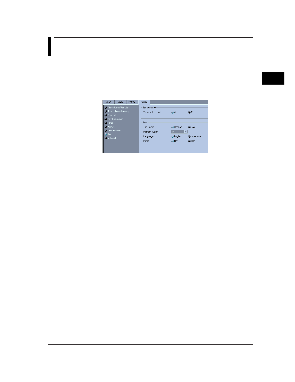
1. Displaying the menu
Click the [Setup] tab and select [Aux], or select [Setting] - [SET [Basic] Setting] [Setting] - [Tag] from the menu bar.
2. Tag Select
Select [Channel] if you want to display channels in channel nos., or select [Tag] if you
want to display channels in tag names. The color of the selected option will switch to
blue.
3
Hardware Configurator
3-45
Page 59

3.41 Setting the Memory Full Relay Output Time
The software can check the current free space in the internal memory and cause the
memory full relay to activate at the specified time prior to the time at which the internal
memory is expected to run out of free space. This time is called memory alarm time.
Operating Method
1. Displaying the menu
Click the [Setup] tab and select [Aux], or select [Setting] - [SET [Basic] Setting] [Setting] - [Memory Alarm] from the menu bar.
2. Memory Alarm
Set the desired memory alarm.
3-46
Page 60
3.42 Selecting the Display Language
The language of messages to be displayed can be selected. The selectable languages
vary with the options and RD-MV currently connected to the PC.
Operating Method
1. Displaying the menu
Click the [Setup] tab and select [Aux], or select [Setting] - [SET [Basic] Setting] [Setting] - [Language] from the menu bar.
2. Language
Select the desired language.
3
Hardware Configurator
3-47
Page 61

3.43 Selecting Whether or Not to Use the Partial
Expand Function
This section explains how to select whether or not the partial expand function is to be
used.
Operating Method
1. Displaying the menu
Click the [Setup] tab and select [Aux], or select [Setting] - [SET [Basic] Setting] [Setting] - [Partial] from the menu bar.
2. Partial
Select [Use] if you are going to use the partial expand function, or select [Not] if not.
The color of the selected option will switch to blue.
3-48
Page 62

3.44 Setting the Key Lock Function
The key lock function for keys and external media can be enabled or disabled. The
password to be used to cancel the key lock function can also be specified.
Operating Method
1. Displaying the menu
Click the [Setup] tab and select [Kay Lock/Login], or select [Setting] - [SET [Basic]
Setting] - [Setting] - [Key Lock] from the menu bar.
2. Key Lock
Used to select whether or not to use the key lock. If [Use] is selected, a list of the keys
and external media which can be subjected to this function will be displayed.
3. Lock/Free
For each key and media, select [Free] if you want to enable the function, or select
[Lock] if you want to disable the function.
3
Hardware Configurator
3. Password
Enter the password to be used to cancel the function.
Note
• The password can consist of up to six characters. For characters which can be used for
the unit, refer to 3.62, "Usable Characters".
3-49
Page 63

3.45 Setting the Login/Logout Function
The login function and user ID can be set.
Operating Method
1. Displaying the menu
Click the [Setup] tab and select [Key Lock/Login], or select [Setting] - [SET [Basic]
Setting] - [Setting] - [Login] from the menu bar.
2. Use Login
Select [Use Login] if you want to use the login function.
3. Auto Logout
Select [Auto Logout] if you want to use the auto logout function. If this function is
used, a logout will be made after a certain time has elapsed following the login.
4. Use ID
Select [User ID] if you want to use the user ID. When [User ID] is selected, the [User
ID] field will become available.
5. ON/OFF
Select [ON] if you want to use the user settings, or select [OFF] if not. If [ON] is
selected, the current user registration will be effective.
6. User Name
Enter a user name (up to 16 characters). For characters which can be used for the
unit, refer to 3.62, "Usable Characters".
7. User ID
Enter a user ID (up to 4 characters). For characters which can be used for the unit,
refer to 3.62, "Usable Characters".
8. Password
Enter a password (up to 6 characters). For characters which can be used for the unit,
refer to 3.62, "Usable Characters".
9. Setup
Used to select whether or not to permit the ID setting to be changed in setup mode.
Enable Possible to enter setup mode.
Disable Not possible to enter setup mode.
Note
• If a user name for which [ON] is selected is also used for another user, [OFF] will be
selected for the user that has the larger user no.
• If [Disable] is selected for all the users for which [ON] is selected, [Enable] will be selected
for the user who has the smallest user no.
3-50
Page 64

3.46 Assigning a Remote Control Function to Each
Remote Control Terminal
A remote control function can be assigned to a total of eight remote control terminals.
This setting is available if the RD-MV100/RD-MV200 has the remote function.
Operating Method
1. Displaying the menu
Click the [Setup] tab and select [Alarm/Relay/Remote], or select [Setting] - [SET
[Basic] Setting] - [Setting] - [Remote Action] from the menu bar.
3
Hardware Configurator
2. Selecting a remote control function for each remote no.
The following control functions are available.
NONE, ALARM ACK, MEMORY START/STOP, MANUAL SAMPLE, TRIGER,
MESSAGE 1, MESSAGE 2, MESSAGE 3, MESSAGE 4, MESSAGE 5, MESSAGE 6,
MESSAGE 7, MESSAGE 8, PANEL 1 LOAD, PANEL 2 LOAD, PANEL 3 LOAD,
MATH START/STOP, MATH RESET, TIME ADJUST
Copying the Settings
The settings made to a remote no. can be copied to another remote no.
1. Click the source remote no. The color of the remote no. will switch to red.
Note
• If you want to copy the settings of two or more remote nos., select the corresponding
remote nos. by dragging them
2. Click [Copy].
3. Click the destination remote no. The color of the remote no. will switch to red.
Note
• If you want to copy the settings to two or more remote nos., select the corresponding
remote nos. by dragging them
4. Click [Paste].
The settings will be copied.
3-51
Page 65

3.47 Setting the Timers to be Used for TLOG
A total of three timers to be used for TLOG can be set. When the time set on a timer
expires, the data will be saved to the TLOG file or math will be reset.
Operating Method
1. Displaying the menu
Click the [Setup] tab and select [Timer], or select [Setting] - [SET [Basic] Setting] [Setting] - [Timer] from the menu bar.
2. OFF
Select [OFF] if you are not going to use the timer.
Using as an Absolute Timer
3. Select [Absolute].
4. Interval
Select the period of time to be elapsed before a time-up.
5. Ref.time
Set the clock time to be used as the reference. The timer starts at the specified clock
time, and a time-up will occur when the specified interval elapses.
6. Save Data
Select this option if you want to save the data to the TLOG file when a time-up occurs.
7. Reset
Select this option if you want to reset math when a time-up occurs.
8. Repeat the above steps for each timer.
Using as a Relative Timer
3. Select [Relative].
4. Interval
Set the interval between time-ups. A time-up occurs each time the specified interval
expires.
5. Save Data
Select this option if you want to save the data to the TLOG file when a time-up occurs.
6. Reset
Select this option if you want to reset math when a time-up occurs.
3-52
7. Repeat the above steps for each timer.
Page 66

3.48 Setting the Report Function
Various reports (hourly, daily, weekly and monthly) can be created. It is possible to
create an hourly report only, daily only, daily and weekly, or daily and monthly. A total of
30 channels are available for this function in the case of RD-MV200 (12 channels in the
case of RD-MV100).
Operating Method
1. Displaying the menu
Click the [Setup] tab and select [Report], or select [Setting] - [SET [Basic] Setting] [Setting] - [Report] from the menu bar.
3
Hardware Configurator
2. Type
Select the desired type of report. The color of the selected type will switch to blue.
3. Time
Set the date/time or day of week/time on which the report is to be created.
4. ON/OFF
Used to enable (ON) or disable (OFF) the report channel.
5. RefCh
Assign a target channel (measurement/math channel) to the report channel.
6. Sum Scale
Used to set whether the math result of the TLOG.SUM math channel is to be
converted to time values before being reported. Select [Off] if you are not going to
convert.
3-53
Page 67

3.48 Setting the Report Function
Copying the Settings
The settings made to a report channel can be copied to another report channel.
Operating Method
1. Click the source report channel no. The color of the channel no. will switch to red.
Note
2. Click [Copy Details].
3. Select the item(s) to be copied, and then click [OK].
4. Click [Copy].
• If you want to copy the settings of two or more channels, select the corresponding channel
nos. by dragging them
5. Click the destination report channel no. The color of the channel no. will switch to red.
Note
• If you want to copy the settings to two or more channels, select the corresponding
channel nos. by dragging them
6. Click [Paste].
The settings will be copied.
3-54
Page 68

3.49 Setting the TCP/IP
Before communicating with the RD-MV100/RD-MV200 via Ethernet, the IP address,
subnet mask and default gateway of the RD-MV100/RD-MV200 must be set.
Operating Method
1. Displaying the menu
Click the [Setup] tab, select [Network], and then click the [TCP/IP] tab.
Selecting [Setting] - [SET [Basic] Setting] - [Comm] - [Ethernet], [Keep Alive], [DNS] or
[Timeout] from the menu bar will also have the same result.
3
Hardware Configurator
2. IP Address
Set the IP address.
3. Subnet Mask
Set the subnet mask.
4. Default Gateway
Set the default gateway.
5. DNS
Used to select whether or not to use DNS. Select [ON] if you are going to use it, or
select [OFF] if not.
6. Primary Sever IP Address
Set the IP address of the primary DNS server.
7. Secondary Sever IP Address
Set the IP address of the secondary DNS server.
8. Host Name
Enter the host name.
3-55
Page 69

3.49 Setting the TCP/IP
9. Domain Name
Enter the domain name.
10. Domain Suffix 1
Enter the domain suffix 1.
11. Domain Suffix 2
Enter the domain suffix 2.
12. Keep Alive
Used to select whether to enable or disable keep alive. Select [ON] to enable it, or
select [OFF] to disable.
13. Time Out
Used to select whether to enable or disable time out. Select [ON] to enable it, or
select [OFF] to disable. If [ON] is selected, enter the desired time out value.
14. Memory Data Out
Used to select the communication module to which the memory data is to be output.
Select [Ethernet] to use Ethernet, or select [Serial] to use the serial interface.
Note
• [Serial] is displayed only if the RD-MV100/RD-MV200 has the serial communication
function.
3-56
Page 70

3.50 Setting the FTP Function
Use of the FTP function enables automatic transfer of a measurement/math data file to
the personal computer.
Operating Method
1. Displaying the menu
Click the [Setup] tab, select [Network], and then click the [FTP] tab, or select [Setting]
- [SET [Basic] Setting] - [Comm] - [FTP] from the menu bar.
3
Hardware Configurator
2. Click the [Primary] or [Secondary] tab.
(The following steps apply whether the [Primary] or [Secondary] tab is clicked.)
3. Server Name
Enter the server name.
4. Port Number
Enter the port number.
5. Login Name
Enter the login name.
6. Password
Enter the password.
7. Account
Enter the account.
8. PASV
Used to select whether or not to use PASV. Select [Use] if you are going to use it, or
select [Not] if not.
9. Initial Path
Enter the initial path.
10. Disp & Event Data
Select [ON] if you want to send a file when memory data is created.
11. Report
Select [ON] if you want to send a file when the report time expires.
3-57
Page 71

3.51 Setting the Serial Communication Function
Operating Method
1. Displaying the menu
Click the [Setup] tab, select [Network], and then click the [Serial] tab, or select
[Setting] - [SET [Basic] Setting] - [Comm] - [Serial] from the menu bar.
2. Baud Rate
Select the desired baud rate.
3. Data Length
Select the desired data length.
4. Parity
Used to select the type of parity check. Select [ODD] for odd parity check, select
[EVEN] for even parity check, or select [NONE] if you do not want to perform any
parity checks.
5. RS232 Handshaking
Select the handshaking method for RS232.
6. RS422A/485 Address
Select the address for RS422A/485.
7. RS422A/485 Protocol
Used to select the protocol for RS422A/485. [NORMAL] or [MODBUS].can be
selected
3-58
Page 72

3.52 Setting the Temperature Unit
This section explains how to set the unit for temperature measurement. Either Celsius
(C) or Fahrenheit (F) can be set.
Operating Method
1. Displaying the menu
Click the [Setup] tab and select [Temperature], or select [Setting] - [SET [Basic]
Setting] - [Temperature Unit] from the menu bar.
3
Hardware Configurator
2. Select C of F by clicking it.
3-59
Page 73

3.53 Setting the File Header, Destination Directory
Name and the Data to be Saved in Manual Save
Mode?
The software allows you to write a comment in the header of a measurement/math data
file, and set the directory where the file is to be saved. It also allows you to select
whether to save all the data or only the data which has not been saved.
Operating Method
1. Displaying the menu
Click the [Setting] tab and select [Message/File], or select [Setting] - [SET [Regular]
Setting] - [File Header] from the menu bar.
2. File Header
Used to enter a comment in the header of the measurement/math data file. Click the
header display area. A comment can now be entered, so enter the desired comment.
Up to 32 characters can be entered. For characters which can be used for the unit,
refer to 3.62, "Usable Characters".
3. Directory Name
Used to specify the directory where the measurement/math data file is to be saved.
Click the currently set directory name. The directory name can now be changed, so
enter the desired directory name.
Note
• The directory name can consist of up to eight characters. For characters which can be
used for the unit, refer to 3.62, "Usable Characters".
The following cannot be used:
AUX, CON, PRN, NUL, CLOCK
• If no directory name is entered, "DATA0" (default directory name) will be given
automatically.
4. Manual Save
Used to select whether to save all the data or only the data which has not been saved
in the case of manual save mode. Select [All] to save all the data, or select [Unsave]
to save only the data which has not been saved.
3-60
Page 74

3.54 Setting the Auto Save Interval for Displayed
Data
If an external media (floppy disk, ZIP, ATA memory card) is set on the RD-MV100/RDMV200, the data in the internal memory can be saved to the media automatically at the
specified intervals. This section explains how to set the interval (i.e. auto save interval).
Operating Method
1. Displaying the menu
Click the [Setting] tab and select [Display], or select [Setting] - [SET [Regular] Setting]
- [Trend/Save Interval] from the menu bar.
2. Auto Save Interval
Select the desired auto save interval.
Note
• This setting is available only if [Event Data Sample Mode] is set to [Free] and [Data] is set
to either [DISPLAY] or [EVENT & DISP] in Memory Sample setting. For details, refer to
3.39, "Setting the Save Method for Measurement/Math Data".
3
Hardware Configurator
3-61
Page 75

3.55 Assigning a Function to the USER Key
A function can be assigned to the [USER] key. Pressing the [USER] key during operation
will cause the assigned function to be performed.
Operating Method
1. Displaying the menu
Click the [Setting] tab and select [User Key], or select [Setting] - [SET [Regular]
Setting] - [User Key] from the menu bar.
2. User Key
Select the desired function from the list. The color of the selected function will switch
to blue.
3-62
Page 76

3.56 Adjusting the Setup Data
Data Adjust button
This section explains how to check whether the setup data matches the actual system. If
they do not match, the data will be corrected automatically.
Operating Method
1. Click the Data Adjust button.
2. The [Data Adjustment] dialog box will appear, so click [OK] to start data adjustment.
3
Hardware Configurator
3-63
Page 77

3.57 Initializing the Setup Data
This section explains how to initialize the currently edited setup data.
Operating Method
1. From the menu bar, select [Setting] - [Initialize].
2. The [Initialize] dialog box will appear, so click [OK] to start initialization.
3-64
Page 78

3.58 Sending the Setup Data
This section explains how to send the setup data created by Hardware Configurator to
the RD-MV100/RD-MV200.
Operating Method
1. Click the Send button, or select [Comm] - [Send Setting] from the menu bar.
2. A message asking you whether to send the data or not will appear, so click [OK]. All
the created setup data will be sent to the RD-MV100/RD-MV200.
3
Hardware Configurator
3-65
Page 79

3.59 Saving the Setup Data
This section explains how to save the setup data created by Hardware Configurator.
Operating Method
1. From the menu bar, select [File] - [Save] or [Save As].
When [Save] is selected:
The existing file will be overwritten by the setup data. Clicking the Save button will have
the same result.
When [Save As] is selected:
The [Save As] dialog will appear.
Destination directory
File list
Selected file name
File type (pnl only)
2. Select the destination directory and desired file name, and then click [Save]. The
setup data will be saved.
3-66
Page 80

3.60 Printing the Setup Data
This section explains how to print the currently edited setup data.
Operating Method
Setting the printer
1. From the menu bar, select [File] - [Print Setting].
2. Select the printer to be used, paper and print direction.
Showing a print preview
Before starting print, it is possible to view how the data will be printed.
3
Hardware Configurator
1. Select [File] - [Preview].
The [Preview] window will appear.
Starting Print
1. Click the Print button or select [File] - [Print].
2. Select the printer to be used, page range and number of copies, then click [OK].
3-67
Page 81

3.61 Writing Measured Data and Performing Math
The RD-MV100/RD-MV200 can be controlled from Hardware Configurator to start and
stop writing of measured data and math function.
Operating Method
Starting
1. From the menu bar, select [Comm] - [Action] - [Memory & Math] - [Start].
Writing the measured data to the memory and math will start.
Stopping
1. From the menu bar, select [Comm] - [Action] - [Memory & Math] - [Stop].
The measured data will be written to the memory and math will start.
Writing the measured data to the memory and math will stop.
3-68
Page 82

3.62 Usable Characters
The following characters can be used for group names, view group names, messages,
comments for file header, name of the directory where files are to be saved, password
for key lock function, user name, user ID and password for login.
%
( )
#
SP
0 1 2 3 4 5 6 7 8 9
ABCDEFGHI J
K L M N O P Q R S T
U V W X Y Z
A B c D E F g H I j
K L m N O P q R s t
U V w X Y Z
_^" ˚ @
Note
• " ° " is used instead of "^" for the RD-MV100/RD-MV200, and "^" is used instead of " ° "
for Hardware Configurator.
• (") and ( ° ) cannot be used for the following.
Password for key lock
User ID for login
DNS host name for TCP/IP
DNS domain name for TCP/IP
DNS domain suffix 1 for TCP/IP
DNS domain suffix 2 for TCP/IP
Password for FTP
• (*), (+), (.), (/), (") and ( ° ) cannot be used for the name of the directory where files are to
be saved.
* + - . /
3
Hardware Configurator
3-69
Page 83

3.63 Displaying the Version Information
Version Display button
To find the version of the Hardware Configurator, display the [About] dialog box.
Operating Method
1. Click the Version Display button, or select [Help] - [About].
The [About] dialog box will appear.
2. To close the dialog box, click [OK].
3-70
Page 84

Chapter 4 Data Viewer
4.1 Overview of Data Viewer
Data Viewer allows the data created by the RD-MV100/RD-MV200 to be displayed in
waveforms or digital values, as well as to be printed
Starting Method
Click the [VIEWER] button of Launcher, or select [Launcer] – [Data Viewer] from the
menu bar. Data Viewer will start and the following window will appear.
Note
• If you want to open two or more Data Viewers, select [Program] - [RD-MV Standard
Software] - [Viewer] from the Start menu.
4
Data Viewer
Display Contents
Among the files created by the RD-MV100/RD-MV200, the following files can be
displayed:
Display data file (.dds)
Event data file (.dev)
TLOG file (.dtg)
Display and Event data files
Select one group from three groups. A total of 10 measurement and math channels can
be registered to each group.
The following data can be displayed:
Measurement/math data
Measurement/math data between cursors
TLOG File
TLOG math results are displayed in a spreadsheet form for each timer.
4-1
Page 85

4.2 Opening a File
Display data files (.dds), Event data files (.dev) and TLOG files (.dtg) created by the
RD-MV100/RD-MV200 can be opened in Data Viewer.
Operating Method
1. Displaying the menu
Click the Open button or select [File] - [Open] from the menu bar.
Open button
2. Select the correct directory and file type, and select the name of the file to be
displayed from the list.
Directory
File list
File name
File type
4-2
Information about
the selected file
3. Click [Open]. The selected file (waveform) will be displayed.
Note
• Two or more files can be opened simultaneously.
• The number of the files which can be opened simultaneously depends on the personal
computer’s memory size and free space on the disk.
Page 86

Display Type
Zone resize bar
Zone display bar
Grid color slider
Trend display area
Y-axis display area
Background
Trend display
Group tab
Active mark
color slider
button
4.2 Opening a File
Display (event) files can be displayed in two ways: waveform display (trend display) and
digital display.
Waveform Display (Trend Display)
4
Data Viewer
Time-axis
magnification
Zone display area
Date
Group tab Selects the group to be displayed.
Trend display area Area provided to display waveforms.
Y-axis display area Area to display the Y-axis
Time-axis display area Area to display the time-axis
Cursor A
Interlocked with the digital and cursor value display windows.
Waveforms are displayed in the assigned colors and according to the
specified display method.
Dragging the mouse in this area displays cursor A at the start point and
cursor B at the end point.
Measured Displays measured values.
values In the case of a Display data file, the maximum and
Cursor A Circles the cross point of the waveform and cursor.
Cursor B Circles the cross point of the waveform and cursor.
Trigger mark Indicates the trigger position.
When Full Zone or User Zone is selected, only the Y-axis of the active
channel is displayed. When Auto Zone is selected, the Y-axis of every
channel is displayed.
The display range can be selected by the horizontal scroll bar.
Time-axis magnification Displays the zoom in/out magnification.
Cursor B
Collection time
minimum values are shown above and below the line
respectively.
Interlocked with the digital and cursor value display
windows.
Interlocked with the digital and cursor value display
windows.
4-3
Page 87

4.2 Opening a File
Zone display area Area to display/change the display status of each channel
Active mark Indicates the active channel.
The active channel is displayed on top of the
other channels.
Grid color slider Adjusts the grid color between white and black
when dragged vertically.
Background color Adjusts the background color between white
slider and black when dragged vertically.
Axis button Displayed in the color assigned to the channel.
Causes the channel to be active when clicked.
Zone display bar Displays/hides the zone display area.
Zone resize bar Changes the size of zone display area when
dragged to left/right.
Trend display button Displays/hides the channel.
4-4
Page 88

Group tab
Time/data no.
display area
Digital Value Display
Display data file
Active mark
4.2. Opening a File
Channel
information
display area
Cursor A
Selected
cursor range
Cursor B
Maximum
value field
4
Data Viewer
Time/data no.
display area
Event data file
Minimum value field
Group tab
Group tab Selects the group to be displayed.
Channel information display area Displays the channel no., unit and color assigned to the
Time/data no. display area Displays time and data no.
Data display area Displays the recorded values for each channel.
Active mark
Channel information
display area
Data display area
Interlocked with the digital and cursor value display windows.
channel.
Active mark Clicking this area causes the channel to
be active and these marks to appear.
The channel indicated by the marks is
interlocked with the active channel in the
trend display window.
Dragging the mouse in this area displays cursor A at the
start point and cursor B at the end point. The area enclosed
by cursors A and B is highlighted.
Cursor A Interlocked with the digital and cursor
value display windows.
Cursor B Interlocked with the digital and cursor
value display windows.
Maximum value field Displays the maximum values.
Minimum value field Displays the minimum values.
4-5
Page 89

4.2 Opening a File
Math time
display area
TLOG file
Timer no. select tab
Channel information
display area
Timer no. select tab Select the timer to be displayed.
Channel information display area Displays the channel no., unit and color assigned to each
channel.
Math time display area
Displays the date/time when a time-up occurred. Also
displays the status.
: TLOG was stopped.
: Date/time set on the DX was changed during TLOG.
: Power failure occurred during TLOG.
4-6
Page 90

4.3 Displaying the File Information
The information of the active data file can be displayed.
The display contents vary depending on the type of the data file.
Operating Method
1. From the menu bar, select [Information] – [About Document]. The [File Information]
dialog box will appear.
4
Data Viewer
2. Enter a comment. If a comment has already been entered, it can be changed.
Note
• The [Print Setting] dialog box can also be used to enter a comment or change the current
comment (refer to 4.9, “Printing the Data”). An entry or change made in the [File
Information] dialog box will reflect on the comment in the [Print Setting] dialog box.
• The comment can consist of up to 255 characters. The printable number of characters is
restricted.
4-7
Page 91

4.4 Making General Display Settings
General Display Settings button
Operating Method
1. Click the General Display Settings button, or select [View] - [General Display Settings]
from the menu bar.
General Display Settings button
Group tab
Global select button
All the waveforms are
selected or de-selected
each time this button is
clicked.
Display button
The waveform is displayed
or hidden alternately each
time this button is clicked.
Waveform no.
Global display button
All the waveforms are
displayed or hidden each
time this button is clicked.
2. Click the desired group tab. Three groups are available.
3. Channel
Channel to be registered
Incremental copy button
Channels are set in
ascending order,
starting from the first
channel in the selected
channel range.
Display range
Zone (display position)
Display color
Default button
Copy button
Used to set the channel no. to be registered to a waveform no.
The currently registered channel no. is displayed. If you want to register another
channel no., click the currently registered channel no. A list of channels nos. will
appear, so select the desired channel no.
4-8
Note
• If you do not want to register any channels, click [None].
• Clicking the Incremental copy button allows registration of channels in ascending order,
starting from the first channel in the selected channel range. For instance, if the
Incremental copy button is clicked when CH01 has been registered to W01, CH02 will be
registered to W02, CH03 to W03,..., and CH08 to W08.
Page 92

4.4 Making General Display Settings
4. Setting whether or not to display the data
To display the data of a waveform no. (W01 to W10), click the box next to the
waveform no. The data will be displayed when the color of the box is blue. The box is
interlocked with the Trend Display button provided in the trend display window.
To display or hide all the waveforms in the selected channel range, click the Global
Display button.
5. Scale Minimum/Maximum
Used to set the minimum and maximum limits of the display scale. Click the currently
set minimum (maximum) limit. The currently set minimum (maximum) limit can now be
changed, so enter the desired value.
Note
• If the same value is entered for both the minimum and maximum limits, the value greater
than the entered value by one will be set to the maximum value, and the value smaller
than the entered value by one will be set to the minimum value.
• Clicking the Copy button will copy the scale values entered in the first row in the selected
channel range to all the rows in the entire channel range.
6. Zone Minimum/Maximum
Used to set the position (zone) where the waveform is to be displayed. Click the
currently set minimum (maximum) value. The currently set minimum (maximum) value
can now be changed, so enter the desired value.
4
Data Viewer
Note
• The settable range is 0 to 99% for the minimum zone value, and 1 to 100% for the
maximum zone value.
• “0%” indicates the lower edge of the trend display area, and “100%” indicates the upper
edge.
• Clicking the Copy button will copy the zone values entered in the first row in the selected
channel range to all the rows in the entire channel range.
7. Color
Used to set a display color for each waveform. Click the currently selected color. The
[Color] dialog box will appear, so select the desired color and click [OK].
4-9
Page 93

4.4 Making General Display Settings
If you cannot find the desired color and therefore want to create a new color, click
[Define Custom Colors]. The [Color] dialog box will change as follows.
After you have created the desired color, click [?]. The created color will appear in ?,
so click [OK] to accept it.
To restore the default colors for the channels inside the selected channel range, click
[Default].
8. Applying the conditions to the window.
In the [General Display Settings] dialog box, click [OK]. The specified conditions will
apply to the window and the dialog box will close.
Copying the Settings
The settings made to a waveform no. can be copied to another waveform no.
1. Click the source waveform no. The row of the selected waveform no. will be
highlighted.
2. Click [Copy].
3. Click the destination remote no. The color of the remote no. will switch to red.
Note
• If you want to copy the settings to two or more remote nos., select the corresponding
remote nos. by dragging them
4. Click [Paste].
The settings will be copied.
4-10
Page 94

4.5 Setting the Display Zone and Clip
When clipped When not clipped
Data Viewer allows you to set where waveforms are to be displayed. It also allows you to
clip the waveforms.
Operating Method
Zone
1. Click the User Zone, Full Zone or Auto Zone button, or select [Y-Axis] from the menu
bar and select the desired zone from the pull-down menu.
Auto Zone button
Full Zone button
User Zone button
User Zone
Displays the waveforms in their own zones specified in the [General Display Settings]
dialog box.
Full Zone
Displays all the waveforms fully in the entire trend display area.
4
Data Viewer
Auto Zone
Divides the trend display area into blocks so that each waveform can be displayed in one
block.
Clip
The currently displayed waveforms can be clipped. They will be clipped in Y-axis
direction according to the minimum and maximum scale values specified in the [General
Display Settings] dialog box.
Measured values smaller than the minimum scale value will be adjusted to the minimum
scale value, and measured values greater than the maximum scale value will be
adjusted to the maximum scale value.
1. Click the Clip button, or select [Y-Axis] – [Clip] from the menu bar.
Clip button
4-11
Page 95

4.6 Expanding/Contracting the Time Axis in Trend
Display
While waveforms are displayed, the time axis can be expanded (zoom in) or contracted
(zoom out).
Operating Method
1. Click the Zoom In or Zoom Out button, or select [Time Axis] – [Zoom In] or [Zoom Out]
from the menu bar.
Zoom Out
Zoom In
The waveforms will be expanded or contracted along the time axis each time the button
is clicked or the menu is selected.
Note
• The following zoom in/out magnifications are available:
1/000, 1/500, 1/200, 1/100, 1/50, 1/20, 1/10, 1/5, 1/2, 1, 2, 5, 10, 20
• If a cursor is displayed and the first data is not displayed, the waveforms will be expanded
or contracted at the cursor in the center of the screen.
• If both cursors A and B are displayed and the first data is not displayed, the waveforms will
be expanded or contracted at the center between the cursors (the center between the
cursors will be located at the center of the trend display area).
4-12
Page 96

4.7 Reading the Measured Values at Cursors and
Erasing the Cursors
In trend display, the measured values at the positions pointed to by the cursors can be
displayed. Two cursors are available; cursor A and cursor B. It is possible to display the
measured values at both cursor A and B positions, as well as the difference between the
two measured values. The cursors can be erased.
Operating Method
1. Setting cursors
In trend display, point to the position whose measured value is to be displayed, then
drag the mouse to another position. Cursor A will appear at the first position, and
cursor B at the second position.
4
Data Viewer
Cursor A
In digital value display, point to the Date[No.] whose measured value is to be displayed,
then drag the mouse to another Date[No.]. The measured values within the selected
range will be highlighted.
2. Displaying the values at the cursor positions
Click the Cursor Value Display button, or select [Window] – [Control] from the menu
bar.
Cursor B
Cursor A
Cursor B
Cursor Value Display button
4-13
Page 97

4.7 Reading the Measured Values at Cursors and Erasing the Cursors
The [Control] window will open, and the measured values at the cursor positions and the
time on which measurements were performed will be displayed. To fine-adjust the
position of a cursor, click the Cursor Move button located next to the data number. The
cursor will move one data at a time.
3. To erase the cursors, select [View] – [Erase Cursor] from the menu bar.
To select all the measured values from the start to end of measurement, select [Edit]
– [Select All].
When the cursors are erased, all the fields in the [Control] window will become blank.
The cursors in trend display are interlocked with those in digital value display.
When the group is switched to another, the cursors will remain in the same positions
but the measured values for the newly selected group will be displayed.
Moving a cursor in the trend display area while the [Control] window is opened will
cause the values in the [Control] window to change.
Cursor Move button
4-14
Page 98

4.8 Converting the Data Format
While measured data is displayed in waveforms or digital values or a TLOG file is
displayed, the data can be converted to various data formats (ASCII, Lotus and Excel).
Operating Method
1. Displaying the menu
Select [Convert] – [To ASCII], [To Lotus] or [To Excel]. A dialog box like the one
shown below will appear (in the following example, [To ASCII] is selected).
Display data file/event data file
TLOG file
4
Data Viewer
For TLOG file, proceed to step 5.
2. Start/End
Used to set the data conversion range. Enter the first and last data nos. of the
conversion range.
Note
• If the cursors are currently displayed, the range between the cursors will be entered
automatically.
• If no cursors are currently displayed, the first and last data nos. of the file will be entered
automatically.
3. Step
Used to set the conversion data step. If you want to convert all the data within the
selected range, enter “1”. The default is “1”.
4-15
Page 99

4.8 Converting the Data Format
4. Group/Channel
If you want to convert data for certain groups, click the Group radio button, and enter
the group range. All the channels included in the selected groups will be subjected to
conversion.
If you want to convert data for certain channels, click the Channel radio button. Two
buttons displaying the currently selected channels are now available. Click them one
at a time, and select the desired channels from the list.
Note
5. Timer 1/2/3
Select the timers to be subjected to data conversion. The data for the channels to
which the selected timer nos. are assigned will be converted.
6. File
If you want to change the directory where the converted data file is to be saved or the
file name, click [File]. The [Save As?] dialog box will appear.
• For group, the currently displayed groups have been set as default.
• For channel, all the channels have been set as default.
4-16
Select the desired directory from the [Save In?] list box, and enter the file name in the
[File name?] text box. Select the file type from the [Save as type?] list box.
An appropriate extension will be attached to the file name automatically (“txt” for
ASCII, “wj2” for Lotus, “xls” for Excel). Files converted in Lotus format can be opened
by Lotus1-2-3 (Ver2.0 or higher), and those converted in Excel format can be opened
by Excel (Ver4.0 or higher).
7. Click [OK].
The measured data will be converted in the selected data format, and saved in a file
under the specified file name.
Page 100

Example of Data Conversion
ASCII (TLOG file)
Excel (TLOG file)
The file can be read by Excel.
4.8 Converting the Data Format
4
Data Viewer
4-17
 Loading...