

Page 1

Page 2
Page 3

Page 4
Page 5

Table of Contents
Preface
For safe use
Main features and functions
2 1 2
Checking model and attachments
3
3.1 Model check
3.2 Checking attachments
Installation
4
4.1 Mounting location
4.2 External dimensions
4.3 Method of mounting the panel
Connections
5
5.1 Terminal board arrangement
5.2 Precautions while connecting
5.3 Connections of power and protective
conductor terminals
5.4 Connection of measuring input
terminal
5.5 Connection of alarm output terminal
(Option)
5.6 Connection of digital input and
operation selection (Option)
5.7 Connection of communication I/F terminal
Operation
6
Name of component part
7
7.1 Name of front panel and its major
functions
7.2 Name of the key and its functions
7.3 Method of inputting the characters
Screen switching method
8
Name and functions of operation screen
9
9.1 Common operations of operation screen
9.2 Status bar
9.3 Real time trend screen
9.4 Bar graph screen
9.5 Data screen
9.6 Historical trend screen
9.7 Dual trend screen
9.8 Alarm display screen
9.9 Internal memory screen
9.10 Card file screen
9.11 Marker list screen
10
Initial settings
1
2
4
5
5
5
6
6
6
7
8
8
10
11
12
13
15
16
20
21
21
22
23
25
27
27
28
29
30
30
31
32
32
33
34
34
35
Flow chart of HOME settings &
11
MENU settings
HOME settings
12
12.1 Setting HOME settings
12.2 Confirming the specifications using
13
14
15
16
17
HOME settings screen
MENU settings
13.1 Setting MENU screen
13.2 Input operation settings
13.3 Display settings
13.4 Alarm settings
13.5 File settings
13.6 Totalizer reset settings
13.7 Schedule settings
13.8 Marker text settings
13.9 Memory operation
13.10 Network settings
13.11 System settings
Setting/Displaying in WEB screen
14.1 Display and settings of Web screen
Read the recorded data using USB
15.1.Outline
15.2.Operation environment
15.3.Access to data file
Adjustment
16.1 Adjustment
16.2 Adjustment environment
16.3 Preparation
16.4 Connections
16.5 Zero and span adjustment
Recommended parts replacement
interval
17.1 Operation conditions
17.2 Reference of parts replacement intervals
Specifications
18
Appendix A. Report application (Sample)
A-1 Operation environment
A-2 Installation method
A-3 Uninstallation method
A-4 Operation method
A-5 Edit report sheet
39
41
41
43
44
44
48
54
60
62
64
65
66
67
68
74
78
78
85
85
85
85
87
87
87
87
88
89
93
93
93
94
97
97
97
97
97
105
Page 6

PREFACE
Thank you for purchasing the RD9900 series graphic recorder.
Before using your new recorder, please be sure to read this instruction manual which will advise you
on how to use the instrument correctly and safely and how to prevent problems.
1. Separate instruction manuals
The present instruction manual describes the optional specifications of alarm output and report
application of appendix as well as the operation of standard specifications. When the instrument is
provided with the higher order or low order serial communications interface (option), the instruction
manual for communications interface is attached as a separate manual. For other options for which you
need to have instructions, their instruction manuals are attached respectively. Please read these
instruction manuals together with this manual.
2. Request
● Request to instrumentation engineers, constructors, and sale agents
Make sure to deliver this instruction to the operator of this instrument.
● Request to the operator of this instrument
This instruction manual is necessary for maintenance, too. Keep this manual with care until the
instrument is discarded.
- 1 -
Page 7
For safe use
1
This section ”FOR SAFE USE” has been compiled to promote the correct use of the instrument in
order to prevent human injury or damage to property before they occur. Please read the following
information carefully and be sure to observe the warnings and cautions in it.
1. Preconditions for use
This instrument is designed for indoor use by mounting it on an indoor instrumentation panel.
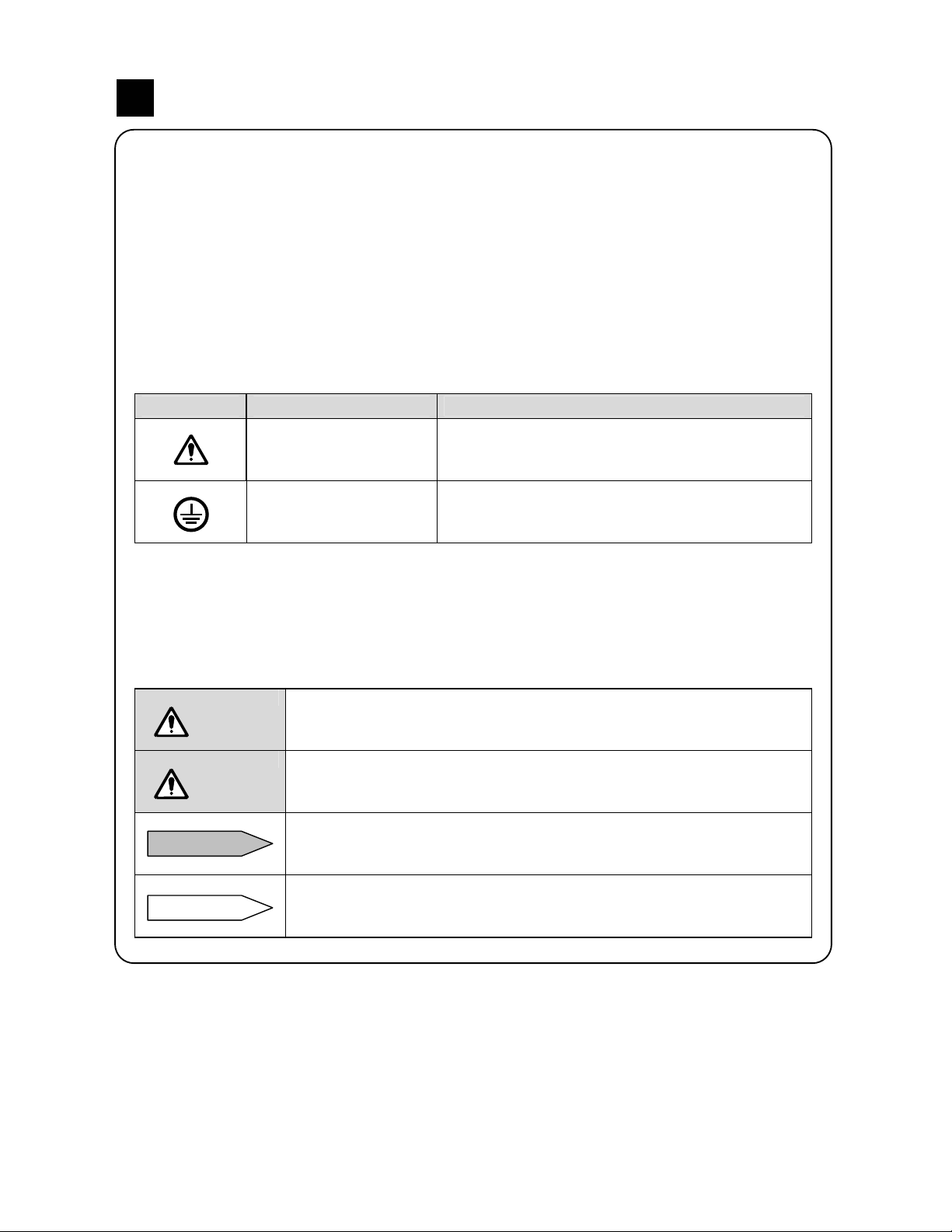
2. Labels on this instrument
The following labels are used for safe use.
Label Name Meaning
Alert symbol mark
Protective conductor
terminal
Indicates the location which should refer to the
manual in order to prevent an electric shock and
injury.
A terminal is provided for connection to the
protective conductor of the power supply facility for
the prevention of an electric shock.
3. Symbols in this manual
The cautions to be observed for preventing the damage of this instrument and unexpected
accidents are sorted by the following symbols according to their importance degrees for enabling
operators to use this instrument safely.
Warning
Caution
Remarks
Reference
The nonobservance of information under this symbol may result in
hazardous, critical or serious injury to the user.
The nonobservance of information under this symbol may result in a
hazardous situation or a light injury to the user or in physical damage to
the property.
This symbol shows a caution when the instrument dose not function as
specified or when such a possibility exists.
This reference servers as a supplement for handling and operation, and it
may be convenient for the user.
- 2 -
Page 8
L N
This paragraph covers important warning for safety to be observed before reading the instructions.
Fully understand the following warning before reading this manual. These warnings are important for
preventing the damage to human bodies as well as accidents.
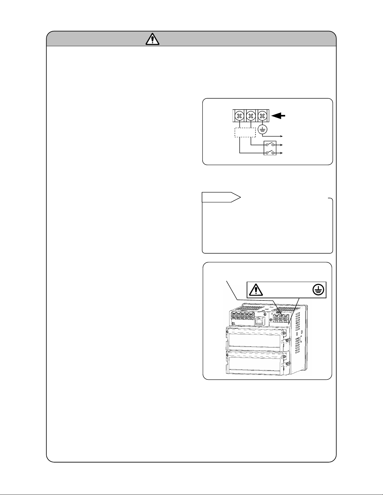
WARNINGS
1. Switch and overcurrent protective device
The RD9900 series graphic recorder in not
provided with a replaceable overcurrent protective
device. Prepare the switch and the overcurrent
protective device for the power supply (circuit
breakers, circuit protectors or the like) within 3m
of this instrument in a location where the operator
can reach instrument in a location where the
operator can reach them handily. Use a switch
and an overcurrent protective device conforming
to IEC947-1 and IEC947-3.
Overcurrent
protective
device
(250V 3A)
Switch
Power/protective
conductor
terminals
To the protective
conductor of power
supply facility
Power supply
2. Be sure to ground the RD9900 series graphic recorder
Before turning the power on, connect the
protective conductor terminal of the RD9900
series graphic recorder to the protective
conductor of the power supply facility. In order to
prevent an accident by electric shock, do not
disconnect an instrument in use.
3. Before turning on the power supply
In order to ensure safety, before turning on the
external power switch make sure that the power
voltage is within the range indicated on the power
supply label.
Reference
Fuse in the power supply
The following fuse is mounted in the power supply
unit of RD9900 series graphic recorder for safety
use. However, this fuse is not replaceable.
Manufacturer:Nippon Seisen Cable., Ltd.
Model:FCT 250V 3A 8H02
Power terminal
Protective conductor terminal
100-240V AC
50/60Hz 50VA MAX
Power
supply label
4. Don’t repair or modify this instrument
Make sure that any persons other than service
engineers approved by ONEGA ENGINEERING
INC. do not repair or modify this instrument by
replacing parts. Otherwise it may be damaged or
will not function normally or an accident such as
electric shock may occur. For ordinary operation,
it is not necessary to open the internal unit.
5. Use this instrument in accordance
with this instruction manual
Use the RD9900 series graphic recorder correctly and safely by following this instruction manual.
ONEGA ENGINEERING INC. will not be responsible for any injury, damage, lost profit or any other
claim, which may result from its wrong use.
6. Turn off the power supply if an abnormal symptom occurs
Turn off the power supply immediately and contact your local OMEGA sales agent if any abnormal
odor noise or any smoke occurs, or if the RD9900 series graphic recorder generates heat that is
too hot to be touched.
- 3 -
Page 9

Main features and functions
2
Besides displaying in various formats like real time trend graph/bar graph/numeric value etc. in 5.6 inch
TFT color LCD and measuring various industrial quantities and temperature of multi channels, this
instrument can as per the requirement, record the data of internal memory and memory card (CF card)
and replay it. Stored data can be used using commercial software like excel etc. Exclusive analysis
software is also available.
Management of
measurement
result is easy
Compliance with
international
standards
Various screen
displays
Various memory
functions
Analog recorder
sensation
Marker function
MODBUS
communication
Measurement result is displayed in various screen formats and monitoring is easy.
The old data stored in CF card can also be read. The stored data can also be
managed using commercial software like EXCEL (Registered trademark of
Microsoft Ltd.) etc.
(Planning to get CE marking compliance)
Real time trend, bar graph, data display (table format) and composite displays like
real time trend and bar graph, real time trend and numeric value display, real time
trend and historical trend can be arbitrarily selected and maximum screens can be
monitored as per requirement. Alarm display screen and marker list screen to
display past alarm activation status collectively, are also available.
Other than maximum 5 groups can be displayed switching over of that screen can
be done by simple operation.
Start/stop of data storage can be done by arbitrary condition settings like key
operation, alarm, time setting etc. and up to 5 files can be stored at a time. During
normal operations, data is stored in internal memory and can be saved on CF
memory card.
As trend screen displays the data on the chart by using scale plate and pointer,
monitoring can be done by analog recorder sensation.
Marker and marker text (alphanumeric characters, maximum 31 characters) can
be written on the trend screen. Marker text is written arbitrarily and also there are
50 types of marker texts that are already registered. This marker text can also be
written in historical trend screen (replay). 'No marker text' marking only, is also
possible.
Parameter settings, data acquisition and operation can be done using high order
communication of option. As communication protocol uses MODBUS it is possible
to communicate with program indicator equipped with MODBUS protocol, even
without creating communication software and building a system is easy.
(MODBUS: Registered trademark of SCHNEIDER Ltd.)
Consumables are
not required
Set up is easy
Software package
is available
Consumables like chart, pen and ink as used in strip chart recorders are not
necessary, thereby making the system cleaner and less time consuming.
Each parameter setting is done by selecting the setting item from menu screen,
using key operation. A window is opened and the method of setting is interactive.
Hence set up is easy.
Also operation can be done easily using the required parameter settings
operation, in ‘Simple settings (HOME)’ screen
Data analysis can be done easily on the PC as software package for exclusive
analysis is available.
● Software for analysis : (Windows98,Me,2000,XP version)
- 4 -
Page 10
Checking model and attachments
3
Model check
3.1
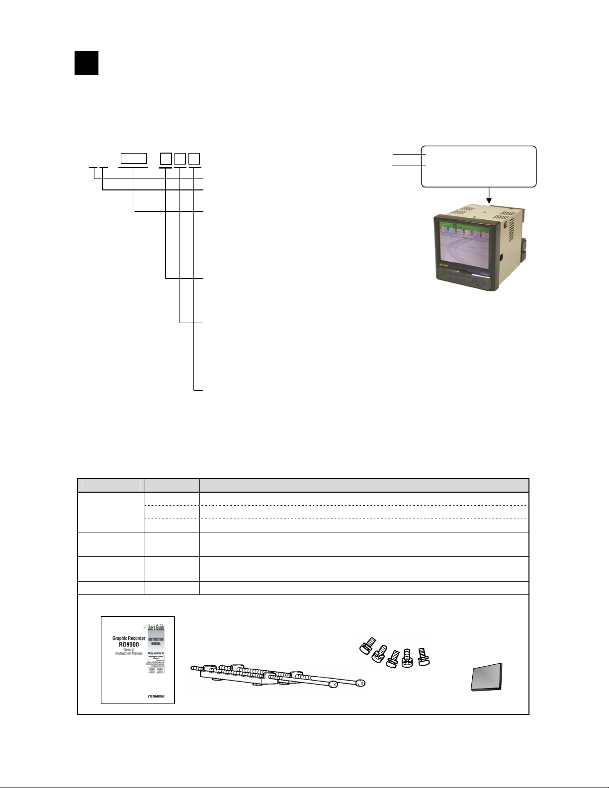
The model No. and serial No. of the RD9900 series graphic recorder can be confirmed by the label on the
upper face of the case.
Please check the model of your instrument from the model code, before use.
■Model code
RD99 -
Model (Check with model code)
Serial No.
Type (Fixed as 2): 2 types
Input type (Fixed as 1): Universal input
(DC voltage, thermocouple, resistor thermometer)
Measurement points/Sampling rate
00: No input
60: 6-point input /100ms
20: 12 point input /100ms
61: 6 point input /1s
21: 12-point input /1s
Communication interface (Option)
N: None
C-24: High order:RS232C(High order)/RS485 (High order) switchable
Low order: RS485
Alarm output, contact input, Power output for transmitter (Option)
0: None
AC-12: Alarm relay output (12 points)
Power supply,
A: Standard power supply
RD99**-***
RD*********
MADE IN JAPAN
3.2 Checking attachments
Package contains the following attachments. Please confirm.
Parts name Quantity Remarks
①Operation
manual
②Mounting
bracket
③Terminal
screw
④CF card
① Operation manual
1
(1 copy)
1
2 For use in panel mounting
5
1 RZ-CMC128 (128MB)
INE-365□ (For RD9900 series graphic recorder) CD-ROM
INE-366□ (Connection/mounting edition) A4 18 pages
RZMC-01-□ (CF card)
For M3.5, input terminal and alarm (digital input) terminal (Spare in case
of loss)
③ Terminal screws
② Mounting bracket
④ CF card
- 5 -
Page 11
Installation
4
4.1 Mounting location
In order to avoid unfavorable effects on measurement accuracy and recording operation, mount the RD
9900 series graphic recorder at the following locations.
1) Industrial environment
Select a place away from electric field and magnetic field and away from mechanical vibrations/shock.
●Over voltage category……Ⅱ
●Pollution degree…………...2 ●Place of use……Indoor
●Altitude…………2000m or less
2) Ambient temperature/humidity
Keep away from direct sunlight and to avoid increase in temperature do no keep the RD9900 series
graphic recorder in a very closed place.
● Place with stable ambient temperature of around 23°C and humidity 50%RH
● Place not exposed to hot drafts (50°C or more), in order to avoid deformation of front panel
● Place where there is no source of heat near the terminal. This is to avoid, measurement errors.
3) Atmosphere
● For safety reasons avoid place where there is inflammable gas.
● Avoid places with dust, smoke, vapors etc.
4) Mounting angle
● Lateral tilting…0°
● Longitudinal tilting…Forward tilting: 0°, Backward tilting: 0-20°
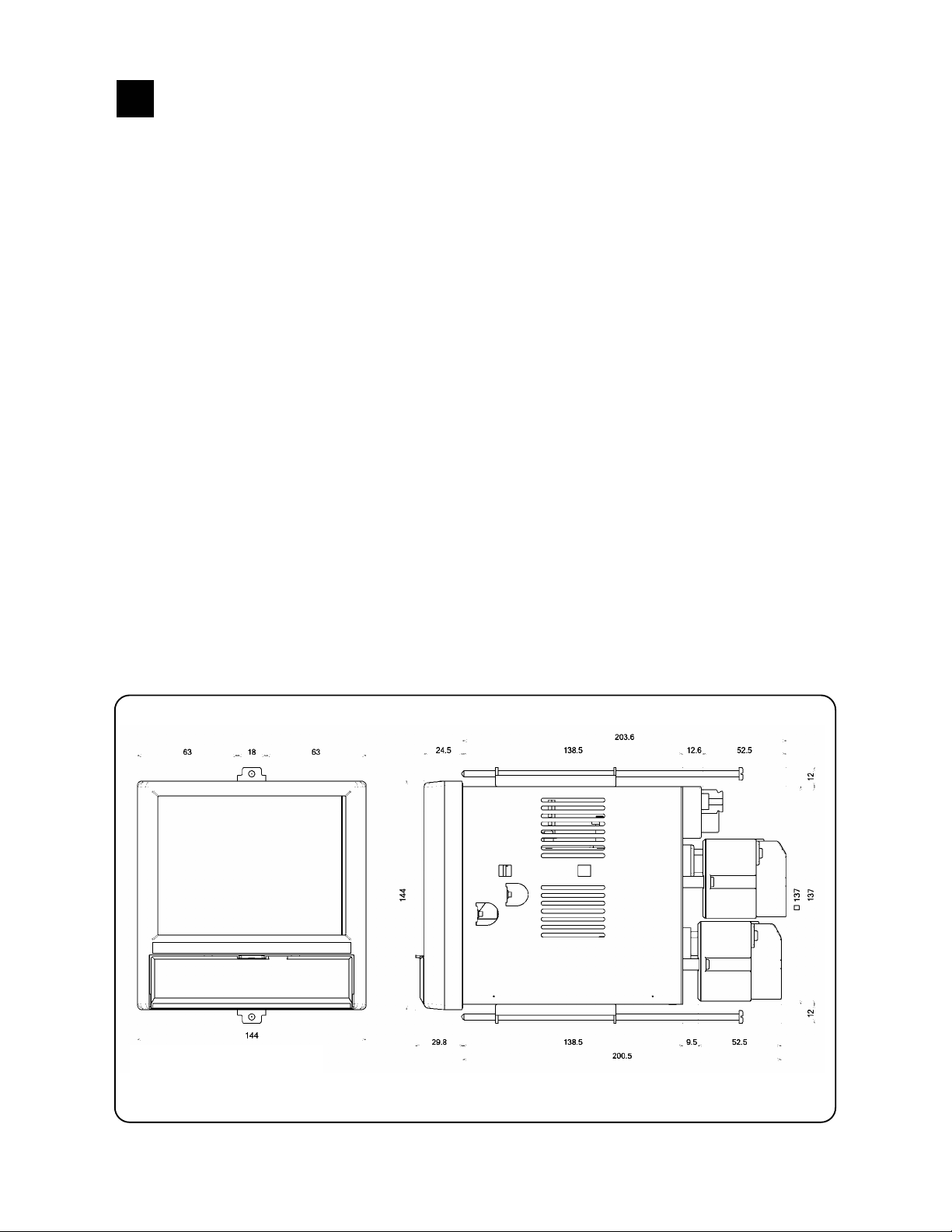
4.2 External dimensions
Following figure shows the dimensions of RD9900 series graphic recorder together with its mounting
brackets.
Unit : mm
- 6 -
Page 12
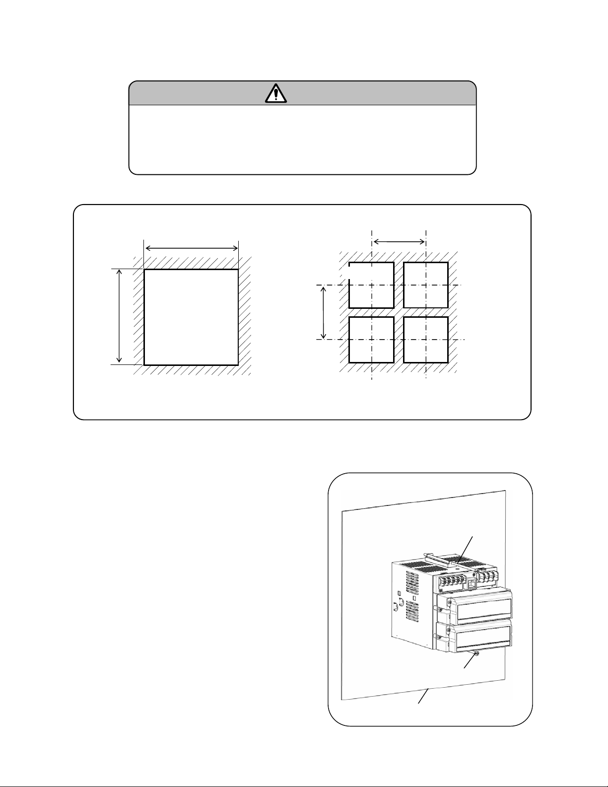
4.3 Method of mounting the panel
1) Panel cut size
2) Mounting method
① Insert the RD9900 series graphic recorder in the
panel cutout from the front of the panel.
② Fixed the RD9900 series graphic recorder using
mounting brackets (Screw tightening torque: 1.0
N・m). Mounting brackets are fixed on the top and
bottom.
■ Mount on the panel and use
① The RD9900 series graphic recorder has been designed to be mounted
on an indoor instrumentation panel.
② Use a panel made of a steel plate of 2mm to 6mm in thickness.
●Minimum interval for installation of multiple instruments
+1
138
0
+1
0
138
パネルカット
(mm)
Warning
200
Panel cut
200
(mm)
Mounting bracket
Mounting bracket
Panel thickness (2 to 6 mm)
- 7 -
Page 13
,mV(-)
,
(B)
)
g
)
3
4
5
6
8
9
0
(
)
A
Connections
5
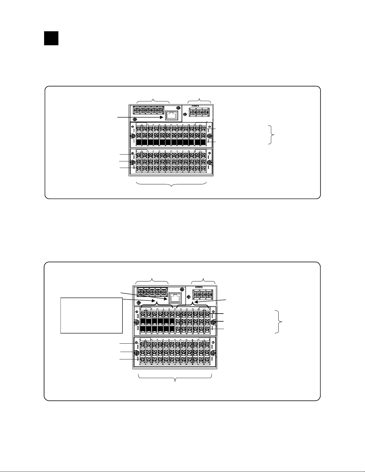
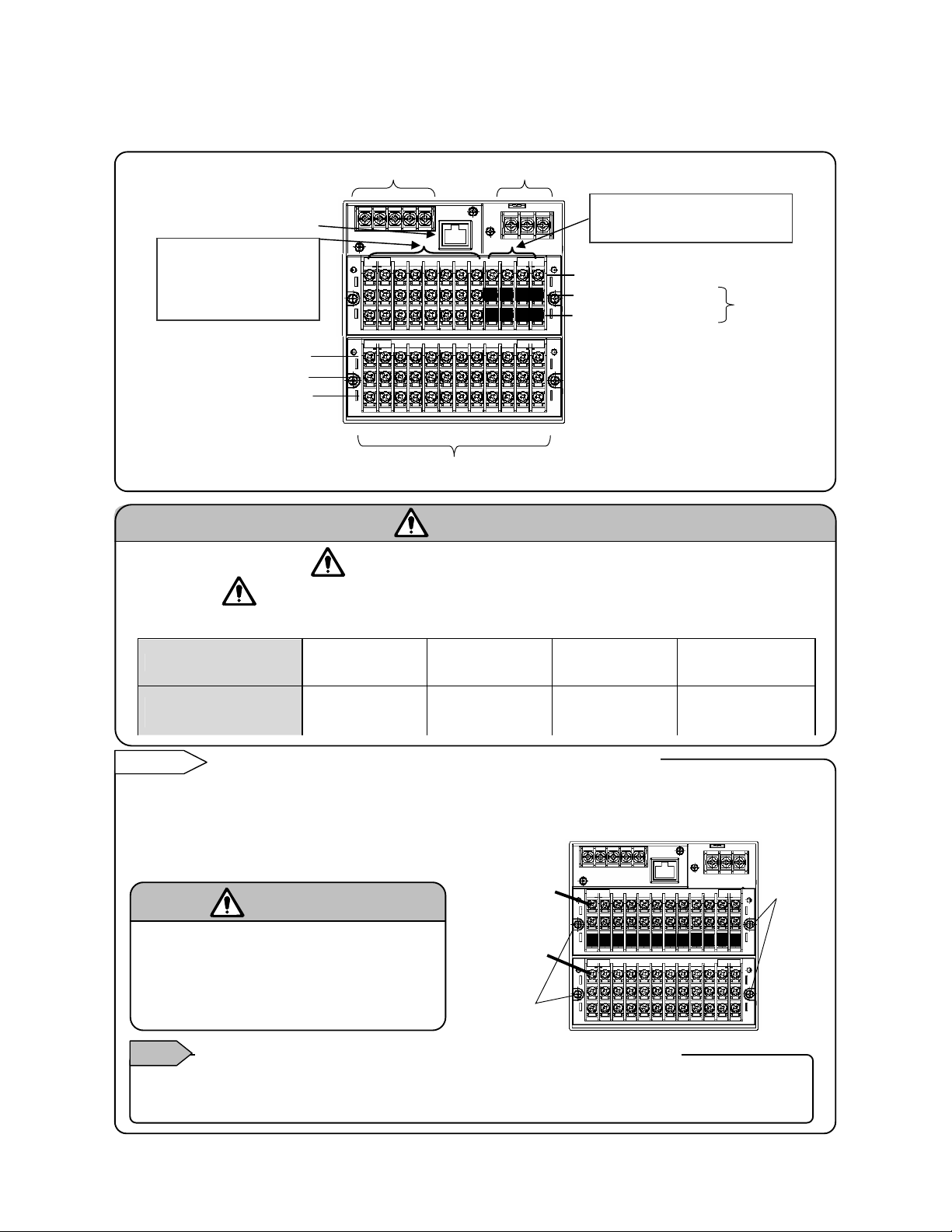
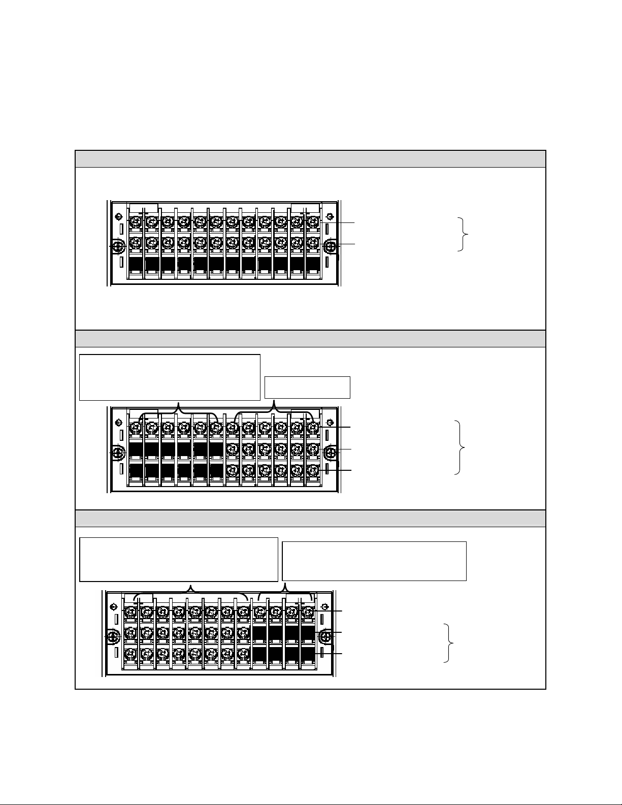
5.1 Terminal board arrangement
The following diagram shows the terminal board arrangement in which option (Alarm relay output [12
points], communication interface) are mounted. Connecter for Ethernet is a standard mounting.
Communications terminal (M4) (for options)
Connector for Ethernet
TC,mV(+), RTD(A) terminal
TC
RTD(B) terminal
RTD
terminal
2
1
Measurin
Following figure is terminal board diagram for option (24VDC transmitter power supply, alarm relay output
[6 points] in RD9900, equipped with communication interface. Connecter for Ethernet is a standard
mounting.
TC,mV(+), RTD(A)
TC,mV(-), RTD(B)
Communications terminal (M4)(option)
Connector for Ethernet
24VDC Power supply
output for transmitter
(From left)
CH1 CH2 CH3
+ - + - + -
terminal
terminal
RTD(B)
terminal
1
2
34
Measuring input terminals
Power/protective conductor terminal (M4)
ø For the connection of communication terminal,
refer to the separate “Communication interface
instruction manual”.
N.O terminal(M 3.5) Alarm relay
terminal(M3.5
COM
(Note) Alarm output in the diagram
is mechanical relay “a”
contact point specification.
7
input terminals(M3.5
7
56
M3.5
11
1
Power/protective conductor terminals(M4)
9
8
10
11
(Note) Measurement input in the
12
12
diagram is 12 points model.
larm output
terminal (M3.5)
N.O
COM
terminal(M3.5)
terminal(M3.5)
N.O
(Note) Alarm output in the diagram is
mechanical relay “C”
connection point specification.
(Note) Measurement input in the
diagram is 12 points model.
output
(12 points)
Alarm relay
output
(6 points)
- 8 -
Page 14
p
Following figure is terminal board diagram for option (digital input [8 points] + alarm MOS relay output [8
points]) in RD9900, equipped with communication interface. Connecter for Ethernet is a standard
mounting.
TC,mV(+), RTD(A)terminal
TC,mV(-), RTD(B)
■Alert symbol marks ( )and places
Remarks
Notes
Communications terminal (M4) (options)
Connector for Ethernet
No voltage contact point
input 8 points input
(From left)
CH1,CH2,CH3-CH8
terminal
RTD(B)
terminal
345
1
2
Measuring input terminals
Alert mark is pasted at places where there is a possibility of getting an electric shock on
touching
Place where the alert
(See the following table).
Terminal name
mark is put
Power supply
terminal
On the lower left of
power supply
terminal
Input terminal and alarm terminal blocks are removable
In order to facilitate connection, the input terminal block and alarm terminal block (including the digital
input terminal block) are removable.
It can be removed by removing to mounting screws along with each terminal block
Each terminal block is connected to the instrument
Turn off the power supply in advance
■
For mounting or dismounting the terminal block,
turn off the external power switch to prevent the
electric circuits from being damaged.
Replacement of thermocouple input terminal block
Caution
Thermocouple input terminal block cannot be replaced by terminal block of any other instrument.
If re
laced measurement error occurs.
Power/protective conductor terminal (M4)
No voltage contact point input
(4 points common)
No voltage contact point input (8 point
input)
COM terminal (M3.5)
terminal (M3.5)
N.O
(Note) Alarm output in the diagram is
MOS relay ‘a’ contact point
specification.
6
8
7
(M3.5)
91011
12
(Note) Measurement input in the
diagram is 12 points model.
Warning
Measurement
input terminal
On the upper left
of terminal cover
Alarm terminal
block
Input terminal
block
Mounting
screw
Mechanical relay
‘c’ contact alarm
terminal
On the upper left
of terminal cover
COM
Alarm MOS
relay output
(8 points)
MOS relay, mechanical
relay ‘a’ contact alarm
terminal
Adjacent to alarm
terminal
Mounting
screw
- 9 -
Page 15
5.2 Precautions while connecting
Points to be taken care of before connecting are given below. Please abide by them for safety and
reliability.
1) Source of power supply
In order to avoid mistake in operations, the power
supplied to RD9900 series graphic recorder
should be single-phase power supply with stable
voltage and without waveform distortion.
① Switch and over current protective device
Add a switch and an over current protective device
(3A) to the power supply in order to avoid an electric
shock. This instrument is not provided with
replaceable fuse.
② Turn off the power supply before connection
Be sure to turn OFF the power supply during
input/output connection and power supply, in order to
prevent electric shock.
Warning
2) Away from strong electrical circuits
Avoid placing the input/output cables near or
besides strong electrical circuits like power line
etc. In case of placing it near or besides strong
electrical circuits, they should be separated by at
least 50cm.
3) Thermocouple input should be away from
source of heat
In order to reduce reference junction
compensation error, place thermocouple input,
especially the terminal part away from source of
heat (objects generating heat). Also avoid the
radiations due to direct sunlight.
■
Secure the connected cables properly
Secure the connected cables so that they are not hooked by a person or a substance,
otherwise the connections may be cut and that may cause an electric shock .
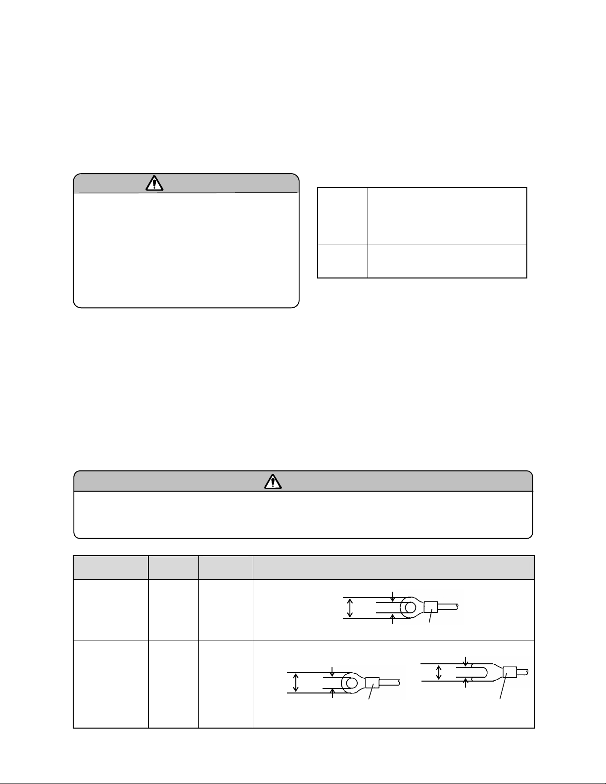
Kinds of terminals and terminal process
Terminal block
Power and
protective
conductor and
communication
terminal
Terminal other
than the above
Screw
diameter
M4 1.2N.m
M3.5 0.8N.m
Tightening
torque
Type O
Type O Type Y
Less than 8
øAs far as possible use TypeO.
4) Keep away from noises
Keep it away from the sources generating noise.
Otherwise unexpected malfunctioning may occur.
In case it is not possible to keep it away from
noise source, take the following
countermeasures.
Major
noise
sources
Counter
measures
●Electromagnetic switch, etc.
●Power line having waveform
distortion
●Inverter
●Thyristor regulator
Insert noise filters between power
supply and input/output terminals.
A CR filter is often used.
5) Use crimp style terminals
① Use crimp style terminal as connection code
terminal to avoid loose or disconnected
terminals and to prevent short circuit between
the terminals.
② Use crimp style terminals with insulating
sleeve to prevent electric shock.
6) Unused terminals
Do not use any unused terminals for relaying,
otherwise electric circuits may get damaged.
.
Warning
Terminal process (Unit: mm)
Less than 8.5
t:0.8
More than 3.7
With an insulation sleeve
More than 4.3
With an insulation sleeve
Less than 8
With an insulation sleeve
t:0.8
More than 3.7
t:0.8
- 10 -
Page 16
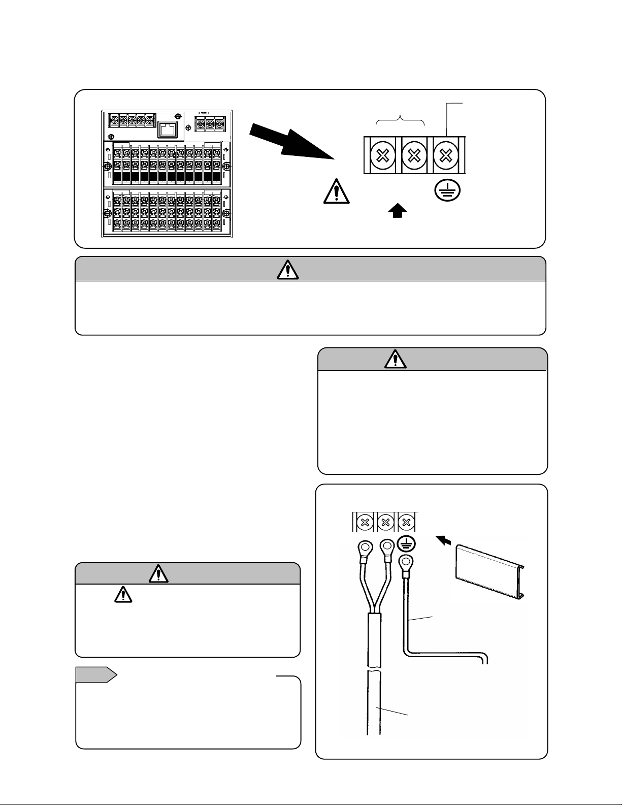
5.3 Connection of power and protective conductor terminals
1) Power and protective conductor terminals
Power supply (voltage, frequency, power consumption)
■Turn off the power supply
Be sure to turn off the power supply before connecting the power supply and protective
conductor terminals to prevent an electric shock.
Warning
2) Connection of power terminals
Power cable used is 600V vinyl insulated cable and
terminal is connected by processing crimp style
terminal with insulated sleeve.
Note: Use the cords with the following standards.
① IEC 227-3
② ANSI/UL817,
③CSA C22.2 No. 21/49
■Be careful with the power voltage and noise
3) Connection of protective conductor
terminal
Be sure to connect to the protective conductor of
the power supply facility. Connection is done after
processing insulating sleeve crimp style terminal.
・ Grounding wire: Copper wire 2mm
(Green/yellow)
■ Mark at power terminal block
A voltage of 100 to 240 V AC is applied to the power
terminals, after connection. Be sure to mount the
power terminal cover after connection, to prevent an
electric shock.
L/N indication of power terminal Notes
It is an indication that conforms to CSA standards
CANADA. Live side of single-phase alternating
current power is L indication and neutral side is N
indication. To get satisfactory performance
maintain the connection of L and N.
2
or more
Warning
Power terminals
L
100-240V AC
50/60Hz 50VA MAX
N
Caution
The power voltage of this instrument is indicated on
the power terminal part. Don’t apply any voltage other
than indicated, otherwise a malfunction or an
accident may result. If there is noise in the power
supply, take countermeasures like installing noise
reduction transformer.
L
Power supply
N
Be sure to connect to the
protective conductor of
the power supply facility.
600 V vinyl insulated cable
Protective
conductor
terminal
Mount the terminal cover
after connections.
A copper wire with 2 mm
or more (green/yellow)
2
-
11 -
Page 17
A
(+)
5.4 Connection of measuring input terminal
1) Measuring input terminal
Connect after switching off the power supply to
prevent electric shock.
● In input terminal, do the connections using crimp
style connection with insulated sleeve.
■Allowable input voltage
ø Channel in which setting are done in a
Input type Allowable input voltage
Voltage,
thermocouple input
Resistance
thermometer input
range of ±5V or higher is ±60VDC
Caution
±10VDCø
± 6VDC
2) Connection of DC voltage (current) input
In order to suppress noise, use twisted cable as
input cable for instrumentation. Connect the current
input after connecting current input shunt resistor to
the channel to be measured.
●DC voltage (DC) input
DC voltage input
Twisted cable
for
instrumentation
(-)
Warning
■Mark on measuring input terminal block
High voltage can be applied to measuring input
terminal, using common mode. The allowable noise
value is lower than 30 V AC or lower than 60 V DC.
Make sure that the noises are lower than the allowable
values. Mount the terminal cover after connection to
prevent electric shock and to protect the input wires. In
the case of thermocouple input, the mounting of the
terminal cover reduces the reference junction
compensation error.
1 2 3 4 5 6
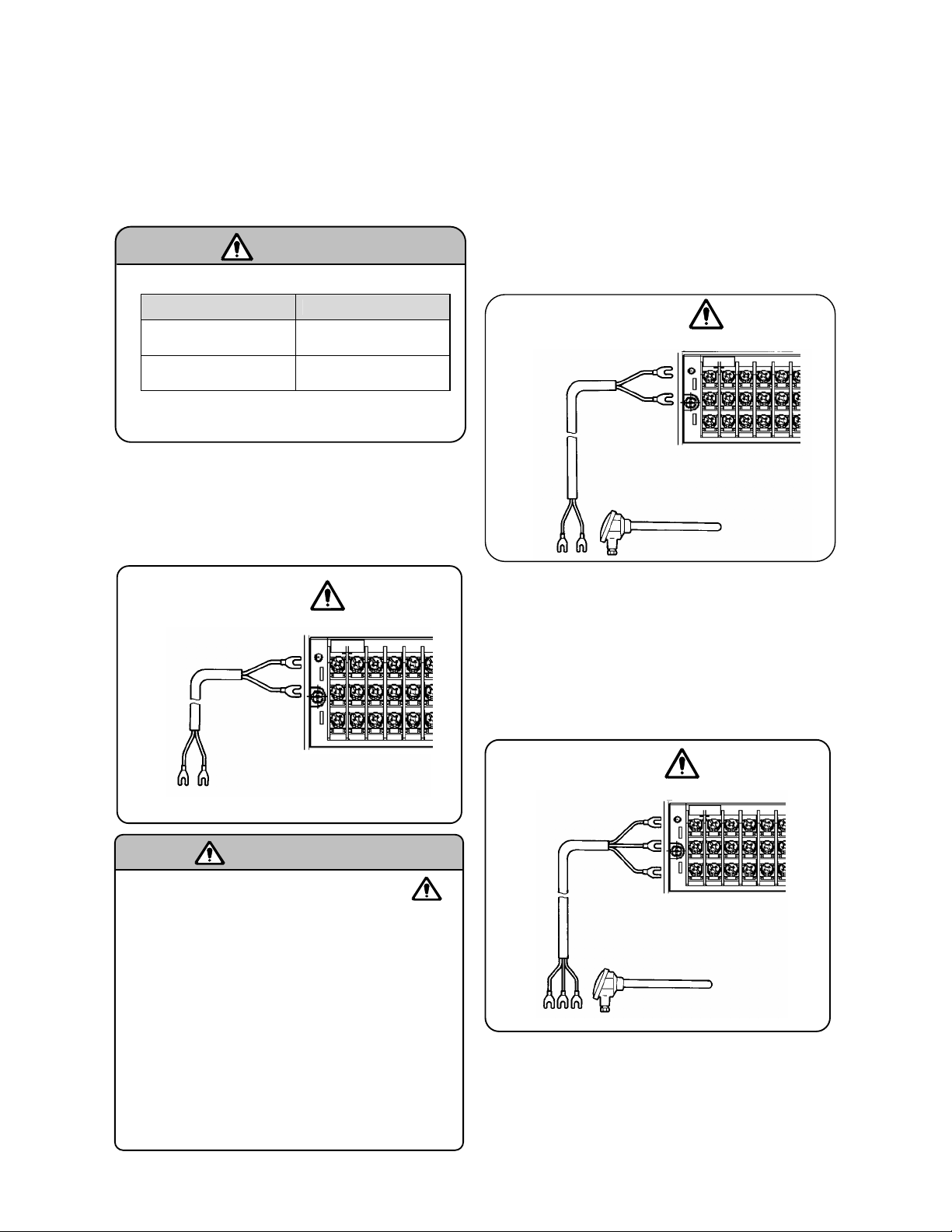
3) Connection of thermocouple (TC) input
Always connect by thermocouple wire (or extension
wire) up to the input terminal of KR 2000 series
recorder. If copper wire is used for connection in
between, noticeable error occurs in measurement.
Avoid using pair of thermocouple wires for
connection in parallel with other instrument
(controller etc) as malfunctioning may occur.
4) Connection of resistance thermometer
In order to avoid measurement errors, use 3-core
input cable, where the resistance value of each
cable is equal.
One resistance thermometer cannot be connected
in parallel with other instrument (controller etc.)
●Resistance
●Thermocouple
(TC) input
Red (+)
White (-)
Compensation
lead wire
(RTD) input
thermometer input
3 core cable
(Same diameter, same length)
Note: The resistance of each cable is
less than 10 Ω. All the 3 wires should be
of the same resistance value.
Resistance thermometer
1 2 3 4 5 6
Thermocouple
1 2 3 4 5 6
B
B
-
12 -
Page 18
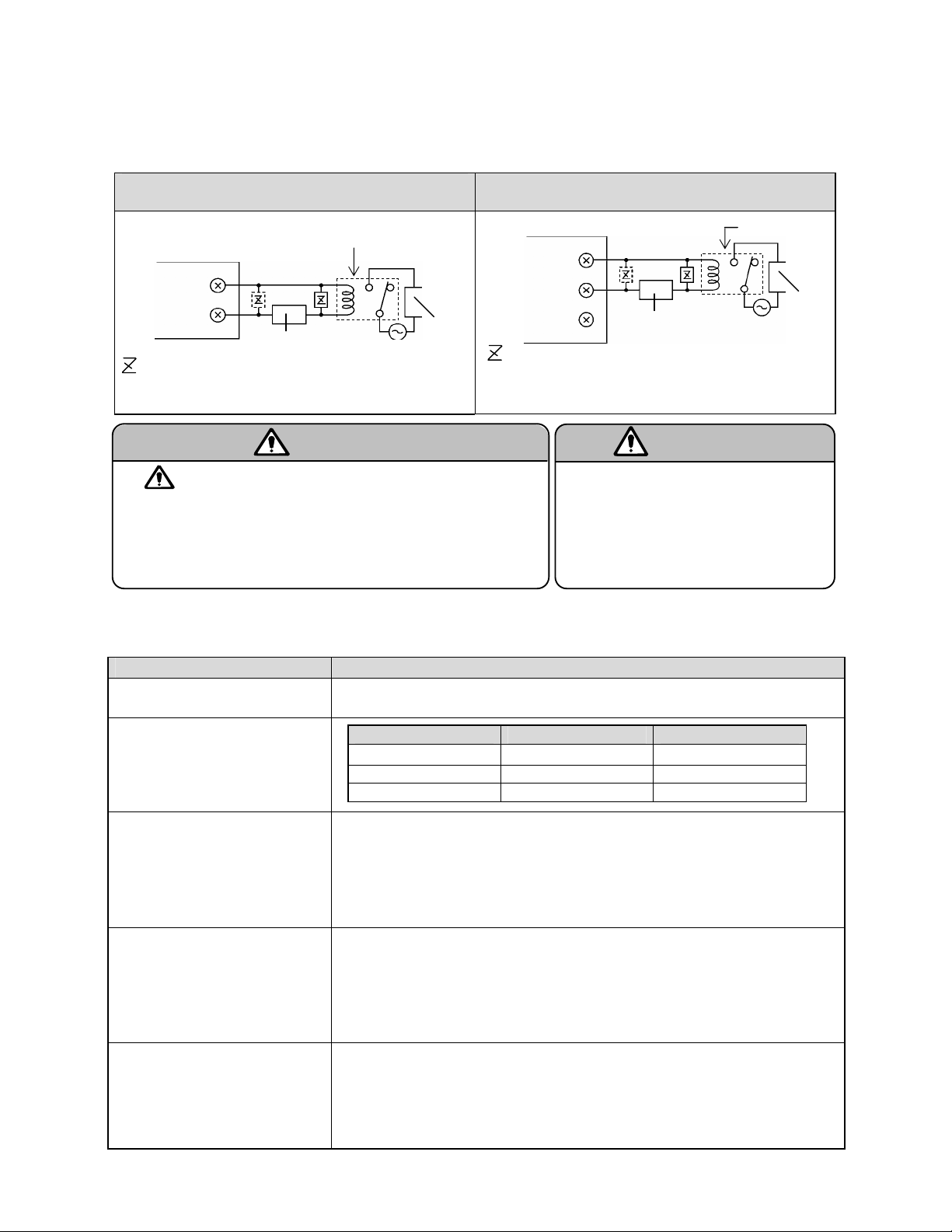
5.5 Connection of alarm output terminal (Option)
Following connections apply only to RD9900 series graphic recorder with alarm output (option).
1) Alarm output terminal
Terminal configuration varies depending on the output specifications.
Alarm relay output (1a)
24VDC Power supply output for transmitter
(From left)
CH1
+ -
CH2 CH3
+ - + -
N.O terminal (M 3.5)
COM terminal (M 3.5)
Alarm relay output (1c)
Alarm relay output
N.O terminal (M 3.5)
COM terminal (M 3.5)
N.C terminal (M 3.5)
Alarm relay
output
(12 points)
Alarm relay
output
(6 points)
(From left)
Digital input (8 points)
DI 1,DI 2,DI 3 - DI 8
Alarm MOS relay output (1a)
Digital input DI COM
(4 points common)
No voltage contact point input 8 point input
COM terminal (M 3.5)
N.O terminal (M 3.5)
-
13 -
Alarm MOS relay
output
(8 points)
Page 19
r
2) Connection
In order to prevent an electric shock, turn off the power supply and buffer relay power supply before
doing the connections.
① Connect to load via buffer relay.
② Connect to alarm output terminal using crimp style terminal with insulated sleeve.
Example of MOS relay and mechanical relay ‘a’
contact output
RD9900 series
graphic recorder
N.O
COM
: Contact point protective element (It is recommended to
mount this element on the a side)
■ mark on alarm output part
Connect a load which does not exceed the specified contact
capacity, to the alarm output terminal. A buffer relay power
supply is applied to the alarm output terminal after connecting.
Hence do not touch this terminal one may get a shock.
Be sure to mount the terminal cover after connections.
Buffer relay
Power
a
Load
b
Warning
Example of mechanical relay ‘c’ contact output
RD9900 series graphic recorde
※ N.C terminal as against N.O terminal is released at
N. O
COM
N. C
※
: Contact protective element (It is recommended to
mount this element on the a side)
the time of alarm activation.
b
Power
a
Caution
Buffer relay
■Take safety measures
Output malfunction may occur in this
instrument due to erroneous
operation/failure, abnormal input etc.
Take safety measures against this as
per the requirement, before using.
3) Precautions for connection
Following are the precautions to be taken during connection.
Item Contents
Contact capacity of MOS relay
output specifications
Contact capacity of mechanical
relay output specifications
(a contact, c contact common)
●Maximum voltage…240V (AC,DC)
●Maximum current…50mA (AC,DC)
Power supply Resistance load Induction load
* Irrespective of load types
100 V AC 0.5 A 0.2 A
240 V AC 0.2 A 0.1 A
30 V DC 0.3 A 0.1 A
Load
Mounting of contact protective
element Z
Selection of buffer relay
Selection of contact protective
element
●Mount the contact protective element that conforms to buffer relay.
MOS relay is broken, if a signal exceeding the contact capacity is
applied even momentarily.
●The mounting position is on coil side (diagram ‘a' of clause 2
‘Connection’ of section 5.5) of the buffer relay that effectively lightens
the load and thus prevents malfunctioning.
(1) Coil rating … Within the contact capacity of output terminals
(2) Contact rating ... Two times or more than the load current
A coil surge absorption element built-in type relay is recommended.
Mount an additional buffer relay if a buffer relay satisfying the load rating
is not available.
Mount this element when buffer relay of surge absorption element built-in
type is not available.
This element is generally composed of C·R (condenser + resistor).
Reference value of C·R
C:0.01µF (Rating around 1KV)
R:100 to 150Ω (Rating around 1W)
-
14 -
Page 20
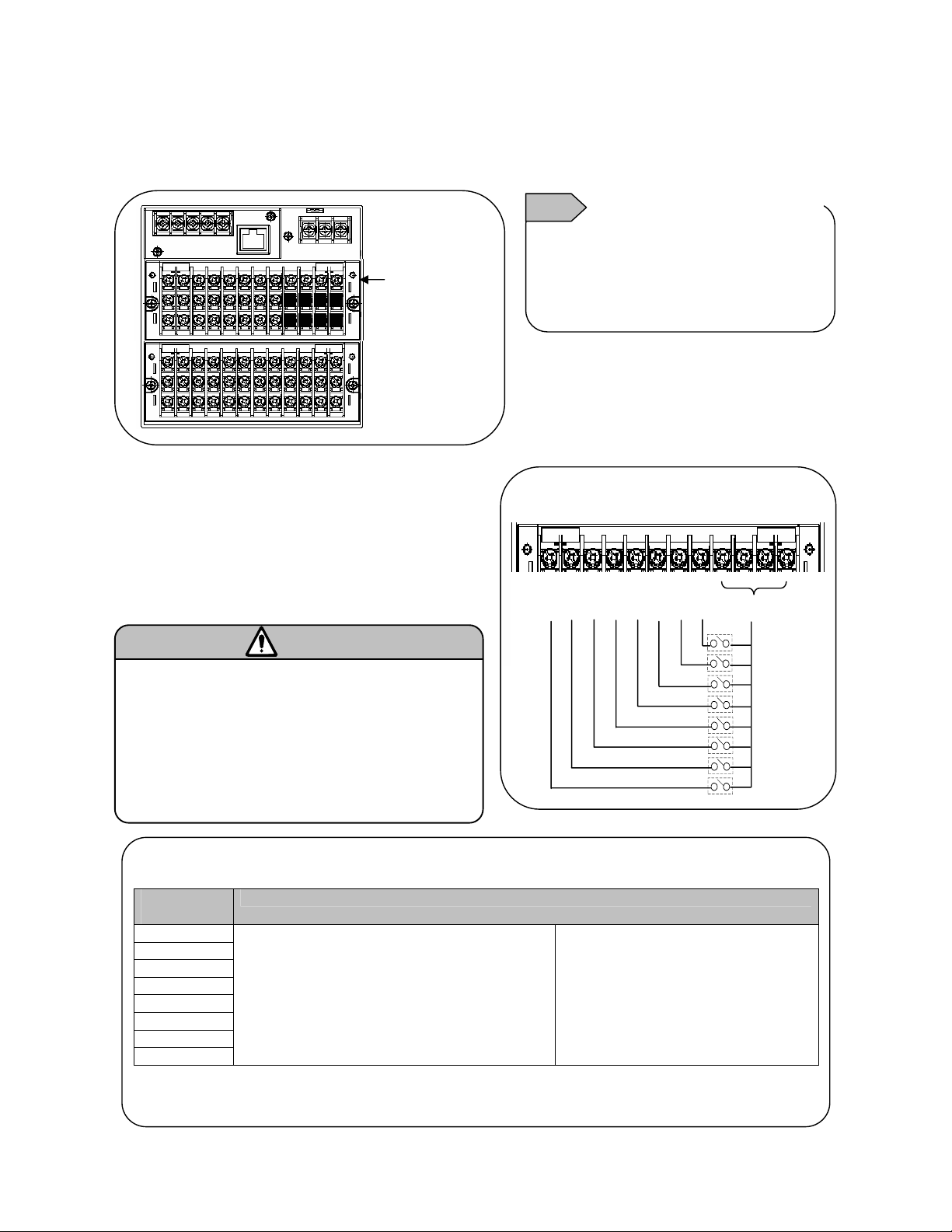
5.6 Connection of digital input and operation selection (Option)
Following connections apply only to RD9900 series graphic recorder with digital input (option).
1) Digital input terminal
Upper step
Digital input
terminal
●Voltage when the contact point is
●
2) Connection
In order to prevent electric shock, turn off the
power supply before connection.
① Apply a no-voltage contact signal to digital input
terminals.
② Connect to digital input terminal using
crimp style terminal with insulated sleeve.
■No voltage contact input
For the contact to be connected to the digital
input terminal, use a switch or relay driven
at lower than 30 V AC or lower than 60 V
DC, or use manual contact supporting very
light loads.
■Function of the terminal
Te rm i na l
name
DI 1
DI 2
DI 3
DI 4
DI 5
DI 6
DI 7
DI 8
●Each function requires a short circuit of 0.1 seconds or more between COM terminal and
each terminal.
Warning
① Digital Input
To be used as contact input
② Pulse Input
To be used as pulse input
③ Integration Reset
Resets integration operation
■Connection example
DI 1 2 3 4 5 6 7 8 COM
Function
Features of digital input terminal Notes
open : Approximately 5 V
Current in case of contact point short
circuit : Approximately 2 mA
④ Marker
Displays marker
⑤ File Drive
Executes recording start/stop of
data file of internal memory
-
15 -
Page 21
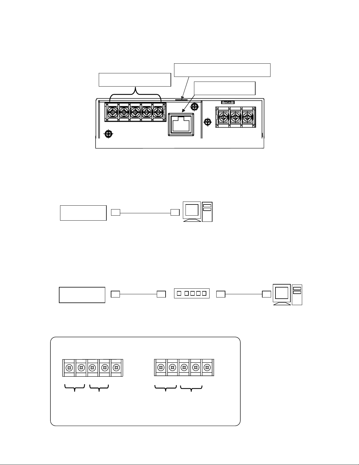
5.7 Connection of communication I/F terminal
The RD9900 communicates with high order instruments via Ethernet and RS232C/RS485, and with low
order instrument via RS485.
RS485/232C terminal
1) When carrying out high order communication using Ethernet
[In case of 1 is to 1 connection with PC]
In case of connecting PC and Ethernet IF as 1 is to 1, use cross type STP cable.
RD9900
STP cross
cable
[In case of N is to N connection with PC]
In case of connecting to existing LAN or a number of PCs, use straight type STP between hub and
Ethernet unit, using switching hub.
RD9900
STP straight
cable
2) Kind of communication terminal
RS485/232C change over switch
Ethernet connector
PC
(With LAN function)
Twist pair
Straight cable
Hub
PC
(With LAN function)
● RS485 + 232C
SA
Low order
*SG is common
SB
RD SD
SG
High order
● RS485 + 485
SB
-
16 -
SA2
SB2
SA1
Low order High order
SG
Page 22
7 8
7
8
7
8
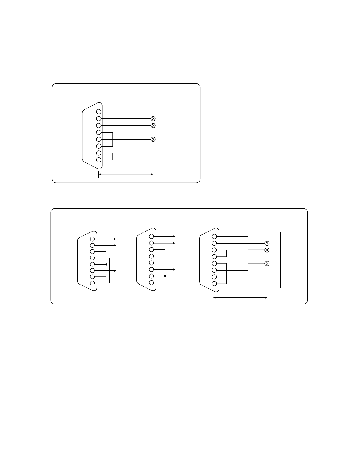
3) High order communication for RS232
There are only 3 communication terminals of this instrument viz. SD,RD and SG and control signal is not
used. General PC uses control signal. The wiring of the control signal in the connector differs depending
on how the PC uses control signal, hence read the operation manual of the PC to be used.
① Example of 9 pin connector
Personal computer
RD9900 series
graphic recorder
1
CD
2
RD
SD
ER
SG
DR
RS
CS
3
4
5
6
7
8
Within 15m
② Example of 25 pin connector
Personal computer
(Example 3)
Personal computer
(Example 2)
2
SD
3
RD
RS
CS
DR
4
5
6
SG
ER
20
RD
SD
SG SG
SD
RD
RS
CS
DR
SG
CD
ER
SD
RD
SG
Personal computer
(Example 1)
2
3
4
5
6
RD
SD
SD
RD
RS
CS
DR
2
3
4
5
6
RD9900 series
graphic recorder
SD
RD
SG
SG
CD
20
ER
20
Within 15m
-
17 -
Page 23
(9-p
7
8
7 8
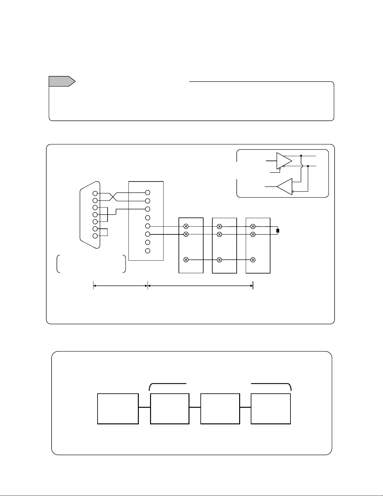
4) Connection of RS232C/485
Connect to the PC using protocol converter (our model:SC8-10).There are only 3 signals viz. SD, RD
and SG between protocol converter and PC and control signal is not used. Wiring process of connector
similar to “(3) High order communication for RS-232” on the previous page, is necessary.
Installing termination resistance
Notes
To ensure the transmission of communication data of RS232C or RS485, termination resistance is
installed in both the terminals of transmission route. When protocol converter (SC8-10) takes both the
terminals of transmission circuit, short ④ and ⑤. By doing this termination resistance is inserted.
① High order communication for RS485
Sent
data
Received
data
Personal computer
Above figure
is an example
of 9 pin connector.
in or 25-pin)ø
2
RD
3
SD
4
ER
5
SG
6
DR
RS
CS
Within 15m
Protocol converter
(SC8-10)
1
RD
2
SD
3
SG
graphic recorder
RDA
RDB
SDA
SDB
4
5
6
Within a total length of 1.2Km (max 31 recorders)
485+485
RD9900 series
SA2
SB2
SG
Internal
circuit
232+485
RD9900 series
graphic recorder 2
1
SA
SB
SG
For wiring process of connector, refer to “3) High order communication for RS-232”.
ø
RD9900 series
graphic recorder 3
SA
SB
Termination resistance
SG
SA
SB
100Ω 1/4W
② Low order communication for RS-485
《Connection example》
RD9900
(High order
instrument)
Low order instrument
RD200
(Low order
instrument)
(Low order
instrument)
RD2800
(Low order
instrument)
SE3000
- 18 -
Page 24
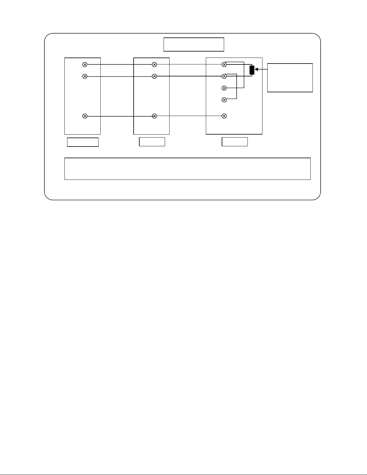
Connection example
SA2
SB2
SA
SB
SDA
SDB
RDA
RDB
SG
SG
SG
RD9900
RD200/2800
SE3000
For details of low order connection instrument, input points and connections of various
instruments, refer to “Communication interface edition”.
Termination
resistance
100Ω・1/4W
- 19 -
Page 25
P
Operation (Be sure to read section to ensure safety.)
6
Initial setting values are set in RD9900 series graphic recorder at the time of shipping them from the
factory Always do the following settings during actual operation.
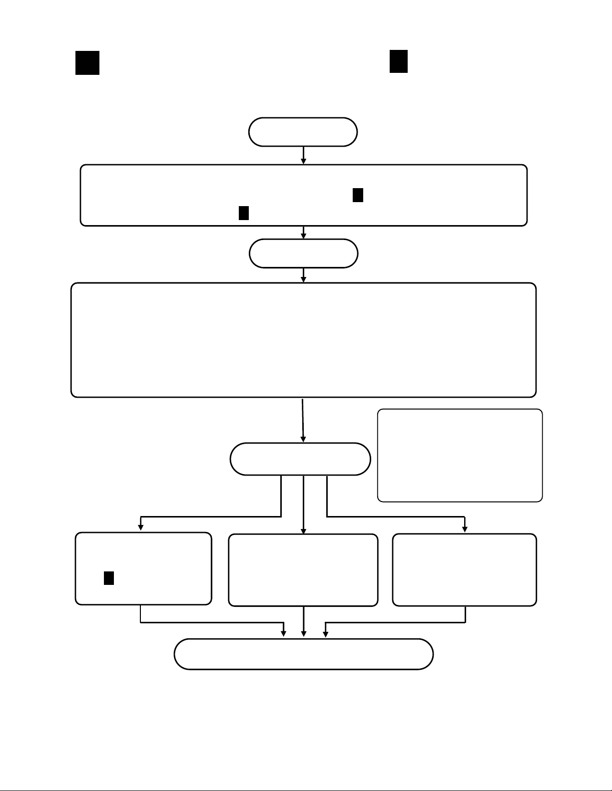
Start
Preparation
① Mount RD9900 series graphic recorder to the panel. ( Installation)
② Finish the connections. ( Connection)
① Initial settings at the time of power supply (10 Initial settings…It is necessary to do these settings)
② Do batch setting by HOME settings mode screen (12.1 Set using HOME settings) or, do individual
settings of each channel by the following sections.
③ Input system settings (13.2 Input, calculation settings)
④ Display system settings(13.3 Display settings)
⑤ Recording system settings (13.5 File settings)
5
Do the following parameter settings.
Start operation
Operation screen
switching
Screen switching
8
method
Start/end operations
of recording
13.5 File settings
ower ON
Settings
4
1
This instrument temporarily stores
the measurement/calculation data
etc. on the inbuilt RAM and does
the data processing, display etc.
In case of saving the data, set the
file and save the data on external
CF card.
Storing the data in
the memory card
13.5 File settings
● On a part of LCD some of the images may always be lit and some may not be lit.
However as a characteristic of LCD there is an uneven brightness and it is not a
malfunction.
End operation Power OFF
- 20 -
Page 26
Name of component part
7
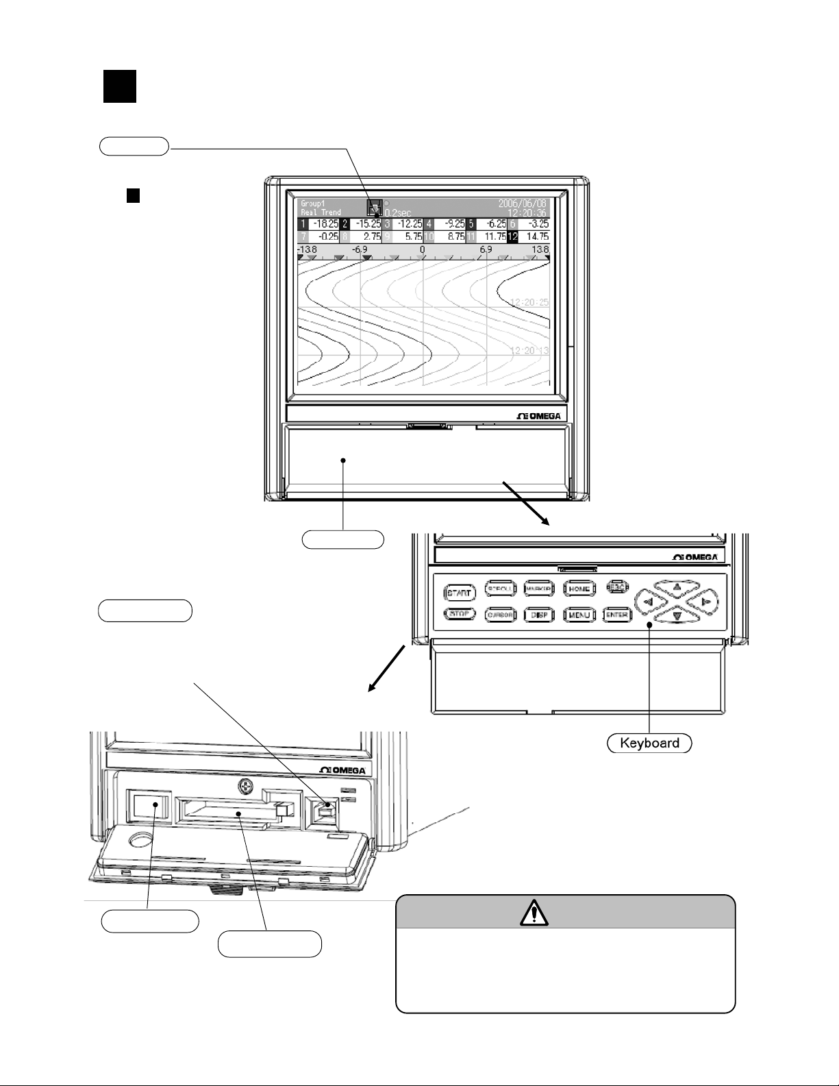
7.1 Name of the front panel and its major functions
Display
5.6 inch TFT color LCD
Operation screen: Refer
to
9
Key cover
USB port
File on the CF card can be accessed
by connecting to the PC.
Key case raised
Key cover raised
Power switch
CF card drive
■Front glass
The front of display part is made by glass. To avoid injuries
due to broken glass, do not blow the glass hard.
- 21 -
Caution
Page 27
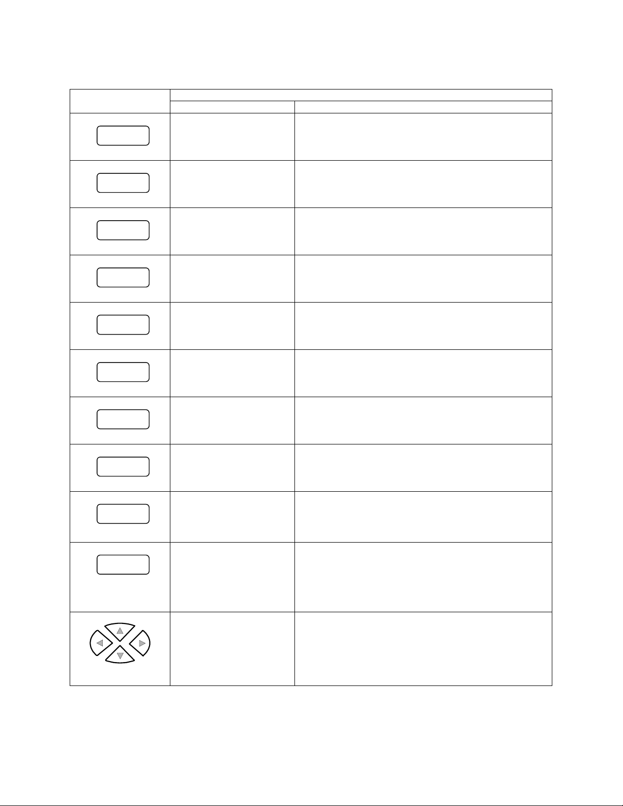
7.2 Name of the key and its functions
Functions and methods of using the key differs depending on operation screen and setting screen.
Key
Recording starts Not used
START
Recording stops Not used
STOP
Key of each screen and their major functions and methods of using
Operation screen Setting screen
Used for switching of
SCROLL
scroll mode and for
moving to historical trend
Used for switching the
CURSOR
cursor mode in historical
trend
Performs marker writing
MARKER
to trend
Not used
Not used
Not used
Displays DISP menu Snapshot is taken by pressing for a long time
DISP
Displays HOME setting
HOME
MENU
ESC
screen
Displays MENU setting
screen
Used for canceling the
menu or for returning to
the previous screen
Exits HOME screen
Returns to the previous screen
Clicked for returning from setting screen to operation
screen and for returning to the previous screen.
ENTER
Direction key
Decides the menu item
and also displays the
ENTER menu
Used for opening the menu that is selected by the
cursor and for deciding the numeric value or character
selected by the cursor.
Used for returning from setting screen to operation
screen and for storing parameters.
Selects menu item and
also changes the display
group and channel
Used for moving the cursor to the left, right, up and
down
- 22 -
Page 28
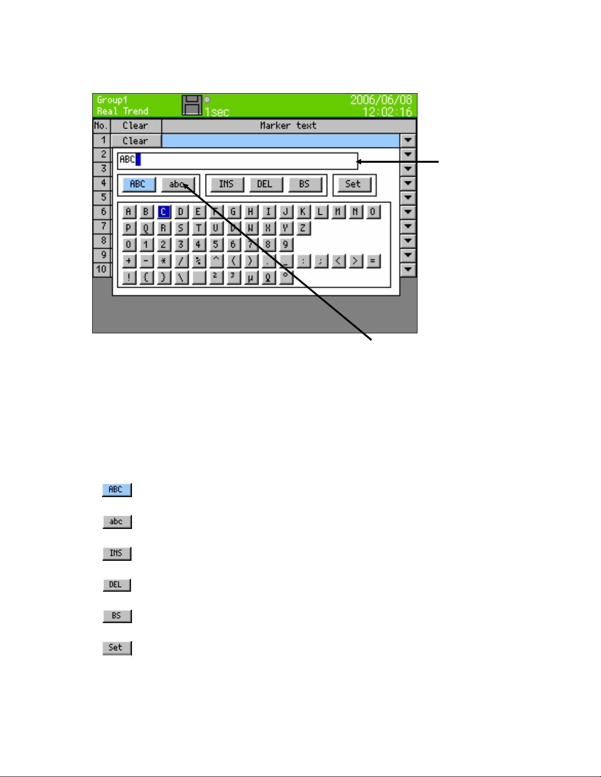
7.3 Method of inputting the characters
Used for inputting/setting the password, setting marker text string, setting tag name etc.
By taking the focus (blue) to upper case English
characters, lower case English characters and Kana,
the input character list underneath, changes.
When character input screen is displayed, if down key of the direction key is clicked, after taking the
focus (blue) to upper case English characters and kana etc. the focus moves to the below column.
When the focus (blue) moves to the below column, move the focus using the arrow key up to the
character to be entered and the click the ENTER key. Selected character is displayed in the character
display column.
Upper case alphabets, symbols and numbers can be entered.
Lower case alphabets, symbols and numbers can be entered.
Insert/overwrite is selected.
(Insert/overwrite toggles at the time of selecting.)
Characters selected in the character input column are deleted.
The character that is one position before the selected character, in the character input
column, is deleted.
Entered character is decided. Similar is the case when ENTER key is
clicked after moving the focus to character input column.
Character display
column
- 23 -
Page 29

MEMO
- 24 -
Page 30
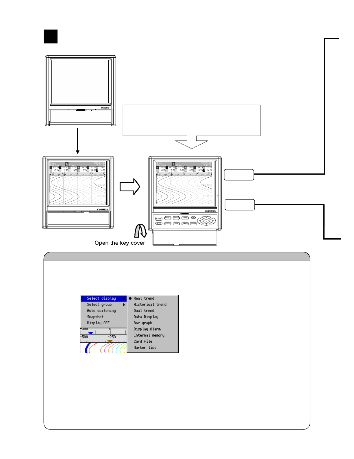
Screen switching method
8
When the power is turned on, operation screen is displayed after
performing the initial operation for about 10 seconds. (Settings at the time
Initial operation
screen
Approximately
Switching of operation screen is done by selecting the DISP menu. Switch over to the desired
screen by doing the following operations.
① DISP menu is displayed by clicking the DISP key.
② Select the menu by using the direction key and on clicking the ENTER key, selected
ø If “auto switching” is selected (status is checked) display group is automatically switched at a
fixed interval.
10 seconds
screen is displayed.
・ Display selection: Display type (Real time trend, data value display etc.) of the
screen can be changed.
・ Group selection: Group to be displayed can be changed.
of shipping from the factory: Real trend screen).When the power supply
was turned ON after changing the operation screen, “Operation screen
that was selected when the power supply was OFF” is displayed.
If the key mentioned on the right is clicked from the
operation screen, one switched over to settings
screen and each parameter can be set.
Switching to settings screen
HOME
MENU
Method of switching of operation screen
- 25 -
Page 31

<HOME settings>
Used in order to facilitate identical settings of all channels. Only some items can be set.
Items being recorded cannot be used.
<MENU settings>
Used for normal settings. All the items can be set. Even while recording, all the settings can be seen
however there are items for which partial setting cannot be done. Items that cannot be set are
displayed in gray.
- 26 -
Page 32

Name and functions of operation screen
9
9.1 Common operations of operation screen
(Method of using each key)
START
STOP
DISP
HOME MENU
ENTER
ESC
(Display data)
Measurement data displayed in each screen
Measurement
data
(Numeric value) Displayed based on display scale settings of each channel
BURN
OVER
UNDER
CAL ER
RJ ERR
Data display is updated every 0.1sec irrespective of the recording interval and excluding historical data
display part of historical trend and dual trend. In order to slow down the updating speed, change “Date
display update interval” (Refer to chapter 13.3.3)
Start the recording. Record in the internal memory the data of the group for which
recording conditions are formed. Group for which recording conditions are not formed is in
waiting status, and recording starts at the time of forming. If recording conditions are not
formed, the status is waiting status.
Storing into CF card is automatically done during save interval and at the time of file
completion.
Stop the recording. Change the recording status of all the groups to stop status. File that is
being recorded is completed and stored into CF card.
Display DISP menu
Menu item Operation contents
Display selection Changes the kind of operation screen.
Select group Changes the display group
Auto switching Automatic switching of group and channels to ON/OFF. When the
Snapshot Saves the hardcopy of the screen to CF card (SNAPSHOT folder).
Display OFF Turns OFF the LCD display. It is redisplayed if some other key is
Displays ENTER menu. Contents of menu differ depending on the screens.
Return to the previous screen. Returns only for real time trend, bar graph and numeric
display.
For vertical trend,
Change the display group using the up and down keys and change the display channel
using left and right keys.
For horizontal trend,
Change the display group using the left and right keys and change the display channel
using up and down keys.
Contents
The upper and lower limits of display scale are displayed as decimal digits.
When kind is “Exponent”, it is displayed in exponential format like “1.2E+3”. In this
case, the significand part after the decimal can be set up to 2 digits however due to
the screen only 1 digit is displayed.
Open circuit the terminal
Value exceeding the upper limit value that can be measured, is measured
Value less than the lower limit value that can be measured, is measured
Calculation error
Instrument is abnormal
.
checkbox is checked the status is ON. Invalid when auto switching
time is set as 0.
clicked.
Each setting screen is displayed.(Refer to chapter 7.2)
- 27 -
Page 33

9.2 Status bar
Status bar is always displayed on the top part of the screen. Displays the status etc. of the instrument.
Normally the back color is green but when the schedule (refer to 13.7) is set, it becomes gray for period
other than the schedule period.
Screen type and group
name that is currently
selected
Back color displays recording status of the group that is currently displayed.
Back color Status
Green Recording. The arrow moves.
Green blinking START key is clicked however, the recording is in wait status as the
Gray
Yellow Remaining capacity of the CF card is less than 10%.
Red CF card capacity is nil.
When X is displayed on the disk mark, it indicates that CF card is not inserted.
Circular stamp on the upper right of the icon shows the access status of CF card. If CF card is
removed when the color is red, one may lose the data. Remove the CF card when the circular
stamp is gray.
Color Status
Gray Not accessing the CF card.
Yellow Writing in the CF card within approximately 5 seconds.
Red Accessing the CF card
Shows the activation status and confirmation status of the icon. Confirmation (ACK) of alarm is done
using the ENTER menu in the operation screen.
Alarm iconø
Icon status Alarm status Confirmation (ACK)
Lit ON Completed
Icon internal blinking ON Incomplete
Icon blinking OFF Incomplete
Hide OFF
Disk icon showing
recording status
etc.ø
Displayed when there are channels that are not
displayed on the screen even though they are
registered in the current group. If the direction
key that the arrow indicates is clicked, the
hidden channels are displayed. AUTO is
displayed in case of auto switching mode.
Recording interval of the group that is currently
displayed and estimate of remaining recordable
time are displayed alternately.
Disk icon
recording condition is not formed
START key is not clicked.(Stopped using the STOP key)
Alarm icon
status
-
Current time
- 28 -
Page 34

9.3 Real time trend screen
Trend of measurement values can be seen by analog recorder sensation. Pen is displayed in the position
of scale plate that corresponds to “Display position” parameter value of each channel. When multiple
channels set the same “display position”, display pen, trend and scale plate in the contents of display
scale of the smallest channel number in the group.
Measurement data of
alarm activation channel
is displayed in red
Marker
display
ENTER menu function
Magnify/reduce Reduce and display the trend time axis.(Same magnification-1/64)
Key operations other than the common operations (9.1)
SCROLL
Displays historical trend (or dual trend) screen. Operation is the same as the operation of selecting the
historical trend (or dual trend) from DISP menu. If historical trend is selected from DISP menu then
historical trend is displayed after that and when dual trend is selected dual trend is displayed.
MARKER
Marker write dialog box is displayed. Recording cannot be stopped.
Marker text registered before hand in MENU settings is selected and
marker is inserted on the trend by clicking the enter key.
When “Input text” is selected, keyboard screen is displayed and
arbitrary text can be inserted.
Can be selected from
data display
(With/without tag), bar
graph and none
- 29 -
Page 35
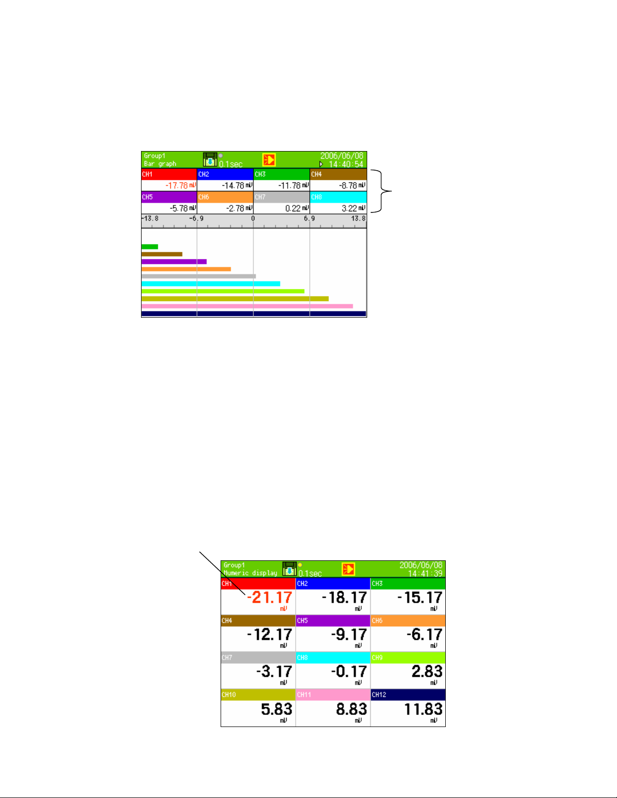
9.4 Bar graph screen
Measurement value is displayed in real time as bar graph and measurement value of each channel can be
seen visually.
The length of the bars and scale plate is displayed in the contents of display scale with smallest channel
number in the group.
Can be selected from data
display (With/without tag) and
none
ENTER menu function
None
Key operations other than the common operations (9.1)
None
9.5 Numeric display
“Measurement data of each channel” and “Alarm activation status” is displayed.
Depending on the “Data display frame count” or number of registration points of the group, data of
channel 1/4/6/12/21/44 is displayed.
Measurement data of
alarm activation channel is
displayed in red
- 30 -
Page 36
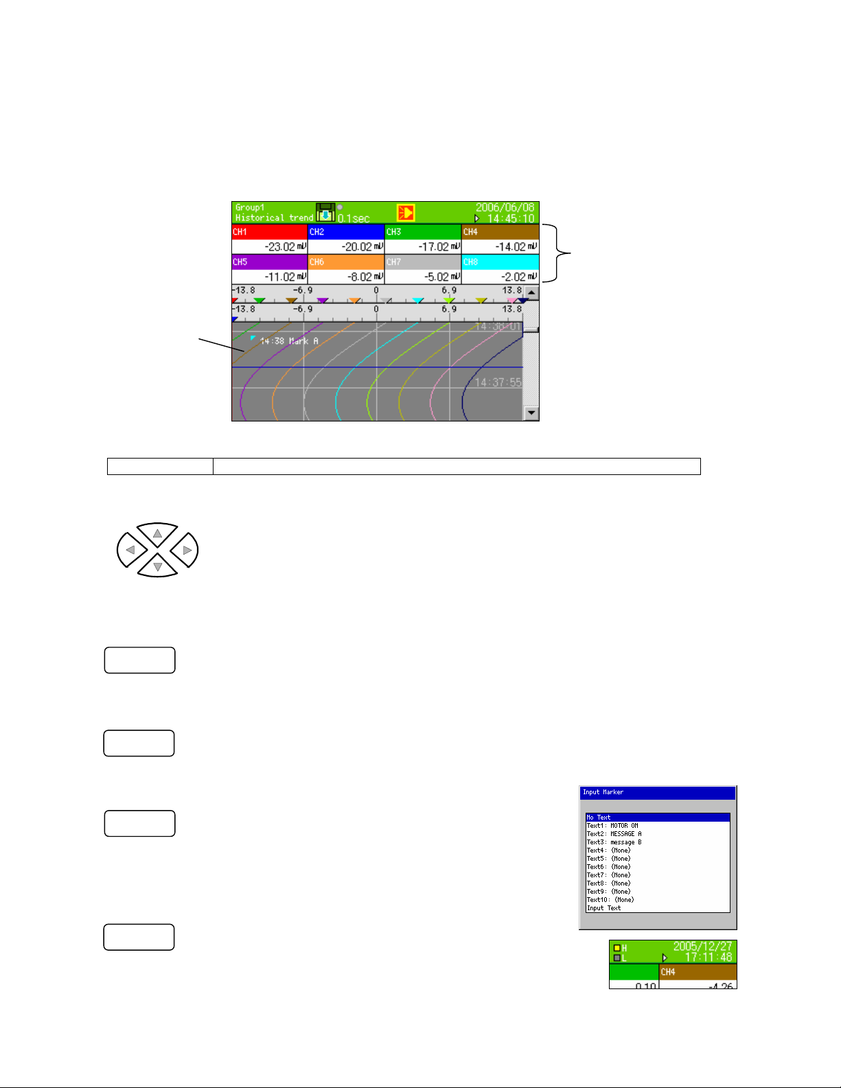
9.6 Historical trend screen
Replays the recorded data and displays it as trend. When “Historical trend” in DISP menu is selected (or
when “SCROLL” key from real trend is clicked), data in the internal memory is displayed. When file is
selected from “internal memory” screen and “card file” screen, data of the target file is displayed.
Historical trend operation method for all the files is the same.
Display method of position of scale plate, trend and pen is same as real time trend.
Market
display
ENTER menu function
Magnify/reduce Reduces and displays the trend time axis.(Same magnification-1/64)
Key operations other than the common operations (9.1)
For vertical trend
Left and right key: Changing the display channel
Up and down key: Moving the cursor when cursor mode is ON and at the time of scrolling the trend
For horizontal trend
Up and down key: Changing the display channel
Left and right key: Moving the cursor when cursor mode is ON and at the time of scrolling the
SCROLL
Scroll mode is switched. When clicked once, scroll bar is enclosed in a yellow frame and
scroll mode becomes ON. In this status if direction key is clicked, screens are scrolled one
by one. When clicked again, scroll mode becomes OFF, and dots are scrolled one by one
using the direction key.
CURSOR
Cursor mode is switched. When clicked once, cursor line is displayed in yellow color and
the cursor mode becomes OFF. In this status if direction key is clicked, scrolling is not done
but cursor line moves. And the data where the cursor is placed is reflected in data display
(or bar).
MARKER
Marker write dialog box is displayed.
Marker text registered before hand in MENU settings is
selected and by clicking the enter key, marker is written in the
position where the cursor is placed.
When “Input text” is selected, keyboard screen is displayed
and arbitrary text can be written.
HOME
When the “data format” of the file to be displayed is
“Maximum/Minimum”, the value to be displayed in data display
(or bar) switches between Maximum/minimum. Other operations
are same as that of HOME key.
Either of the current display is shown in H, L display in the status bar.
Cursor position data display
trend
- 31 -
Page 37

9.7 Dual trend screen
“Real time trend” and “Historical trend” can be split and displayed above and below. Thus the current and
the past data can be compared. Also the data display displays the current value/value of the cursor
position of historical trend by splitting it into above (up) and below (down).
Method of displaying the position of trend and pen is same as that of real time trend however, in case of
settings such as ‘displaying multiple scale plate’, 1 scale plate is displayed, and the numeric value on the
scale plate is not displayed.
Operation method is the same as that of historical trend.
Up: Current measurement value
Down: Historical cursor position data display
ENTER menu function
Magnify/reduce Reduces and displays the trend time axis.(Same magnification-1/64)
Key operations other than the common operations (9.1)
Same as historical trend. (Refer to 9.6)
9.8 Alarm display screen
List of alarms that are activated is displayed. Activation date and time, cancel date and time (cancelled
alarms only), channel (tag name) and kind of alarm are displayed in new order (latest on the top).
Irrespective of the groups all the alarms activated in this instrument are displayed.
Maximum storage count is 1000.If that number is exceeded the oldest ones are deleted.
Selected row is displayed in
yellow color
ENTER menu function
Trend
display
Jumps to the trend of activated date and time of the selected row.
Cannot jump when file not found or when not recorded in activation time.
In this case, the file search is carried out in the order internal memory → CF card.
Key operations other than the common operations (9.1)
SCROLL
Up and down key: Moving the selected row
Left and right key: Not used
Scroll mode is switched. When clicked once, scroll bar is enclosed in a yellow frame and
scroll mode becomes ON. In this status if direction key is clicked, screens are scrolled one
by one. When clicked again, scroll mode becomes OFF, and rows are scrolled one by one
using the direction key.
- 32 -
Page 38

9.9 Internal memory screen
Files recorded in internal memory are displayed
as list. Start date and time, end date (item being
recorded is the latest data time) and time and
data count are displayed. Files are displayed in
new order (Latest on the top).All the files only of
the selected group are selected.
ENTER menu function
Trend display Files of the selected row are displayed as trend.
Key operations other than the common operations (9.1)
Selected row is displayed in
yellow color
Up and down key: Moving the selected row
Left and right key: Not used
SCROLL
This instrument records all the data in the internal memory as a file. This file is copied to the CF card
at the time of file completion and at every ‘save interval’ that is set.
<Limitations of internal memory>
(File capacity)
Approximately 256KB (Excluding header and marker) is taken as one file. File size can be calculated
as follows.
Data volume x Number of channels x recording count
(Usually data volume is 4 bytes, when data format is “Maximum/minimum” it is 6 bytes)
Before reaching 256KB if recording is stopped due to non formation of recording condition, due to
STOP key or due to power off etc, the file is completed at that point of time.
(Number of files)
Maximum number of files that can be saved in internal memory are 250 (In group unit, “250 ÷ Number of
groups used” [Fraction is rounded down]).
(Volume of all files)
Total volume of files that can be saved in internal memory is 64KB X (63÷(Number of groups used) -
2). If it is exceeded files starting from the oldest file are deleted.
Scroll mode is switched. When clicked once, scroll bar is enclosed in a yellow frame and
scroll mode becomes ON. In this status if direction key is clicked, screens are scrolled one
by one. When clicked again, scroll mode becomes OFF, and rows are scrolled one by one
using the direction key.
Internal memory
- 33 -
Page 39

9.10 Card file screen
Files recorded in CF card are displayed as list.
Start date and time, end date (item being
recorded is the latest data time) and time and
data count are displayed. Files are displayed in
new order (Latest on the top).All the files only of
the selected group are selected.
Selected row is
displayed in yellow
ENTER menu function
Trend display Files of the selected row are displayed as trend.
Key operations other than the common operations (9.1)
Up and down key: Moving the selected row
Left and right key: Not used
SCROLL
Scroll mode is switched. When clicked once, scroll bar is enclosed in a yellow frame and
scroll mode becomes ON. In this status if direction key is clicked, screens are scrolled one
by one. When clicked again, scroll mode becomes OFF, and rows are scrolled one by one
using the direction key.
9.11 Marker list screen
Marker recorded on the trend is displayed as list.
Recording date and time and text is displayed in
new order (Latest on the top). Marker, recorded
in the group that is selected, is displayed.
Maximum storage count is 200.If that number is
exceeded the oldest ones are deleted.
Selected row is displayed in
yellow color
ENTER menu function
Trend display
Jumps to the trend position of marker of the selected row.
Cannot jump when file is not found.
Key operations other than the common operations (9.1)
SCROLL
Up and down key: Moving the selected row
Left and right key: Not used
Scroll mode is switched. When clicked once, scroll bar is enclosed in a yellow frame and
scroll mode becomes ON. In this status if direction key is clicked, screens are scrolled one
by one. When clicked again, scroll mode becomes OFF, and rows are scrolled one by one
using the direction key.
- 34 -
Page 40

Initial settings
10
When power supply is switched ON at the time of receipt or when settings are initialized, initial settings
screen is displayed. Please set the minimum required parameters from below.
One can exit without setting other items except power supply frequency. At that time operation is done
with the settings at the time of shipping.
・ Power supply frequency 50Hz/60Hz
・ Clock settings
・ Input settings
・ Display settings
・ File settings
When ENTER key is clicked message is erased and the settings can be done.
① Setting power frequency
When cursor is brought to the item of 50Hz/60Hz using arrow key and ENTER key is clicked, pulldown
menu is displayed.
Move the cursor to the selected frequency using the direction key and then clicking ENTER button.
Confirm the power frequency to be used and set it.
- 35 -
Page 41
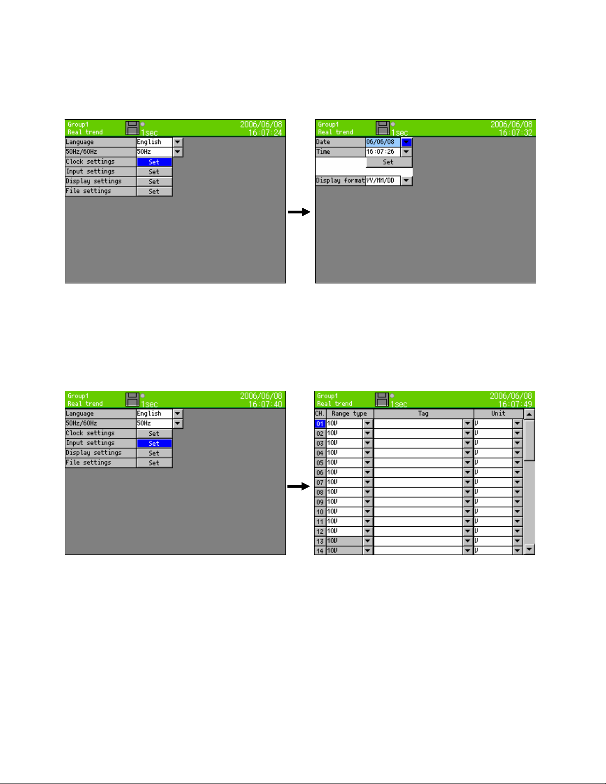
② Setting the clock
Move the cursor to the clock setting item using the direction key and click the ENTER key, the following
clock settings screen is displayed.
øFor detailed settings refer to “13.11.1 Clock settings”
③ Input settings
Move the cursor to the input setting item using the direction key and click the ENTER key, the following
input settings screen is displayed.
øFor detailed settings refer to “13.2 Input operation settings”
- 36 -
Page 42

④ Display settings
Move the cursor to the display setting item using the direction key and click the ENTER key, the following
display settings screen is displayed.
øFor detailed settings refer to “13.3.1 Channel parameters”.
⑤ File settings
Move the cursor to the file setting item using the direction key and click the ENTER key, the following file
settings screen is displayed.
øFor detailed settings refer to “13.5 File settings”.
- 37 -
Page 43

MEMO
- 38 -
Page 44

A
11
Flow chart of HOME settings & MENU settings
Operation
screen
HOME settings screen (HOME key)
MENU settings menu screen (MENU key)
Settings screen
Input operation settings
Display settings
larm settings
File settings
Totalizer reset settings
Schedule settings
Marker text settings
Memory operation
Network settings
System settings
- 39 -
Page 45

Input parameter settings
Recording interval settings
Specification confirmation
List
Channel parameters
Group parameters
Common parameters
LCD settings
Detail settings
ON/OFF settings
Detail settings
Detail settings
Detail settings
Writing the settings to the card
Read the settings from the card
Initializing the settings
Writing the internal memory to the card
Instrument specifications display
Detail settings
Settings of display
Settings of group
Parameter settings of
operation screen
Detail settings
Detail settings
Detail settings
Save settings
Read settings
OK/Cancel settings
OK/Cancel settings
Clearing the internal memory data
Format card
Ethernet settings
FTP server settings
E-MAIL settings
DNS settings
Clock settings
Key lock
Password settings
Other settings
OK/Cancel settings
OK/Cancel settings
Detail settings
Detail settings
Forward address
Transmission condition
Interval transmission channel
Account
Detail settings
Detail settings
ON/OFF settings
Detail settings
Detail settings
Detail settings
Detail settings
Detail settings
Detail settings
- 40 -
Page 46

12
HOME settings
12.1 Set using HOME settings
When “HOME settings” is used, input setting of all channel batch and setting of recording interval can be
done. This facilitates the input/recording confirmation.
□Operation screen
HOME
□Home settings screen
・ Move the focus (blue) to the setting item using direction key.
・ It is decided by clicking the “Enter” key for the item to be set.
■Setting range type
DC voltage
Thermocouple
Resistance
thermometer
■Setting the range
・ Set the scope of range.(It is decided by range type.)
Click
In case of settings for HOME settings, if
HOME key in the operation screen is clicked,
one moves to the screen for doing the
settings. Each of the settings to be done by
the direction key can be done by moving the
cursor (blue) to the desired item and clicking
the ENTER key due to which the selected
screen gets displayed.
13.8mV,27.6mV,69mV,200mV,500mV,2V,5V,10V,20V,50V
K,E,J,T,R,S,B,N,W-Wre26,PR40-20,NiM0-Ni,CR-AuFe,Platinel2,
U,L
Pt100, JPt100,Pt50,Pt-Co
- 41 -
Page 47

■Setting the scale
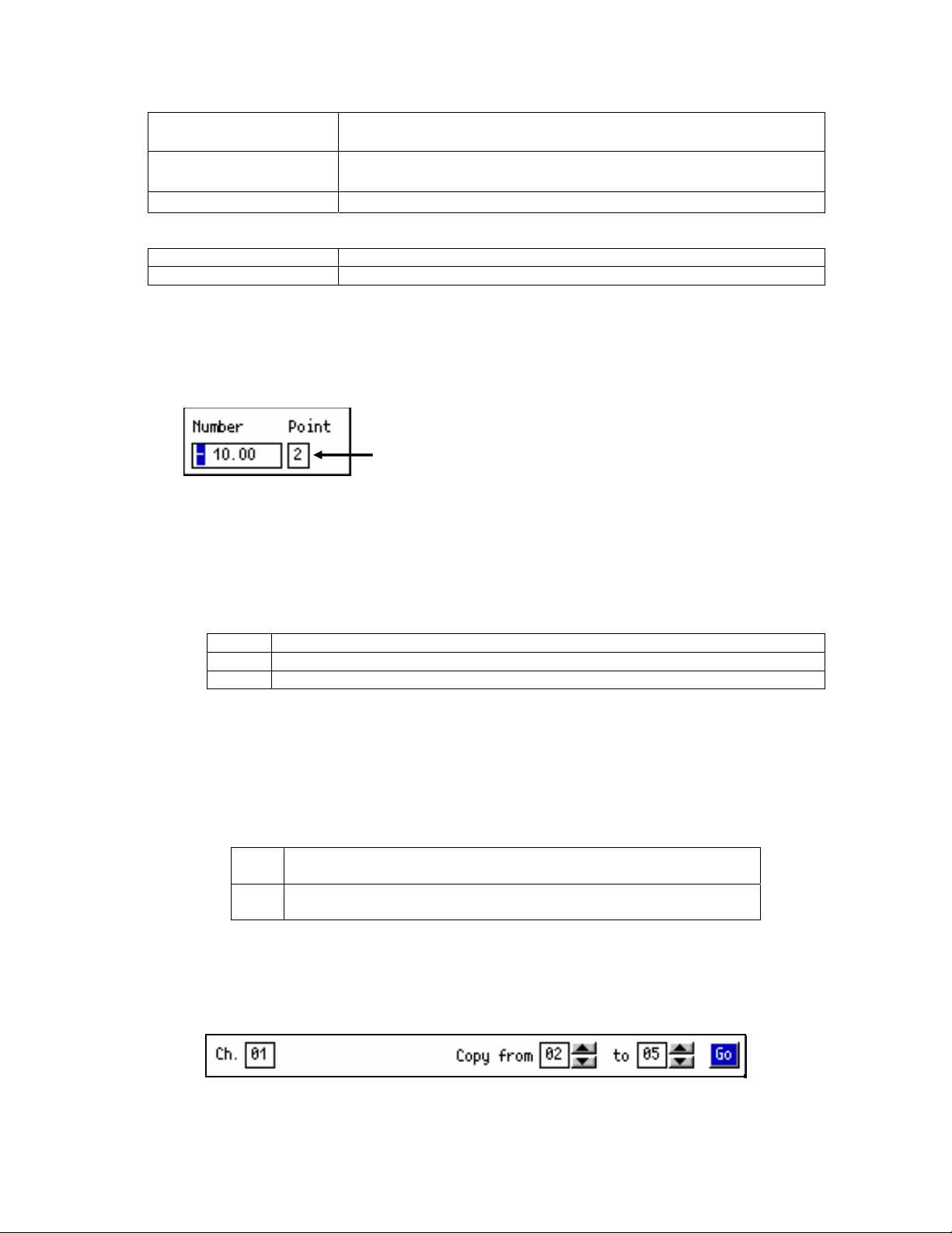
・ Set the scope of range. (It is decided by range type.)
This numeric value decides the position of the decimal point.
■RJ (Reference junction compensation) is set
・ Whether RJ is internal or external, is set.
■Setting burnout
None Burnout function is not used.
UP Set as upper limit burnout.
DOWN Set as lower limit burnout.
■Set the recording interval
Seconds 0.1 second, 0.2 seconds, 0.5 seconds, 1 second, 2 seconds, 3 seconds, 5
seconds, 10 seconds, 15 seconds, 20 seconds, 30 seconds
Minutes 1 minute, 2 minutes, 3 minutes, 5 minutes, 10 minutes, 15 minutes, 20
minutes, 30 minutes, 60 minutes
- 42 -
Page 48

12.2 Confirming the specifications using HOME settings screen
・ Specification information of the instrument can be confirmed.
・ For queries please contact after confirming this screen.
□Operation screen
□Home settings screen
□Specifications confirmation screen
HOME
ENTER
Click
Click
Select: Move the focus to “Specifications
confirmation using “↓”.
In specifications confirmation screen following
can be confirmed,
・ Model
・ Serial number
・ Software version
・ MAC address.
- 43 -
Page 49
p
MENU settings
13
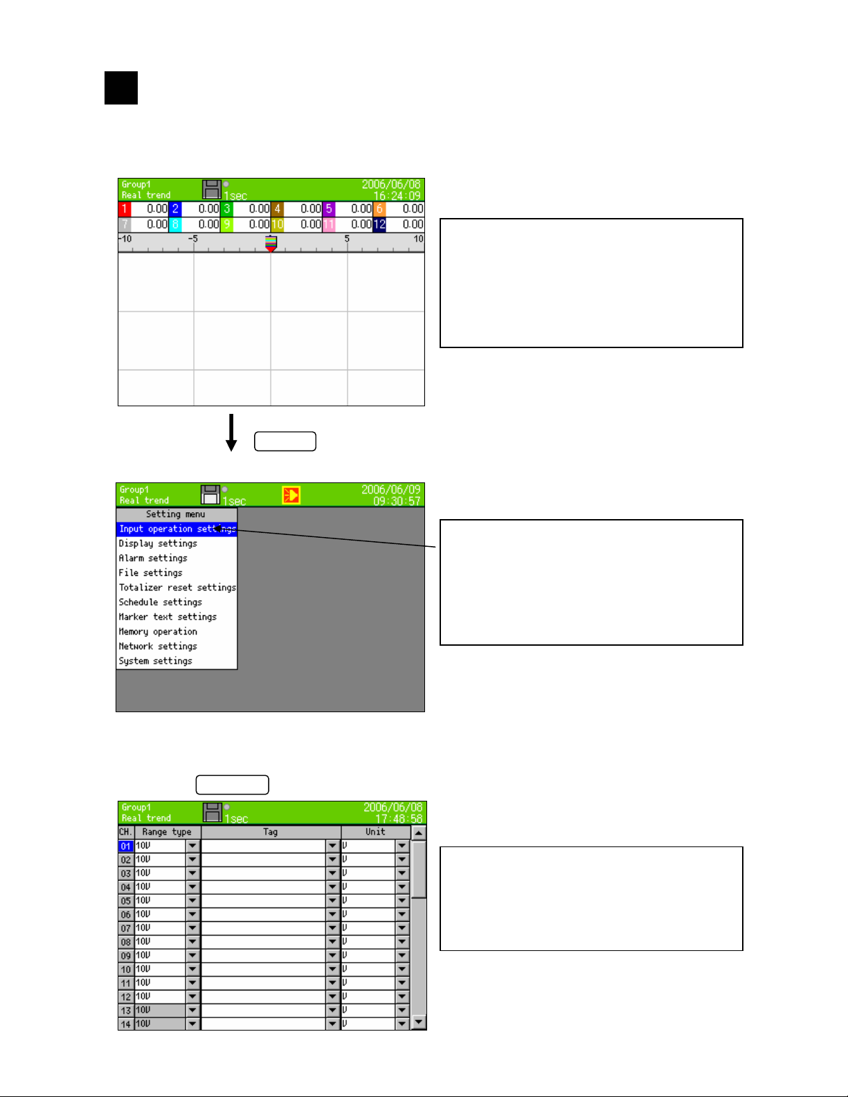
13.1 Setting MENU screen
□Operation screen
□Settings menu screen
□“In
ut operation settings” screen
Select “Input operation settings”
ENTER
MENU
Click
Click
For setting parameter, if MENU key in the
operation screen is clicked, parameter items
that can be set are displayed.
Items to be set are selected by the direction
key and on clicking the ENTER key, one
moves to the screen in which each parameter
is set.
As list box of the parameters is displayed,
select the parameter by moving the cursor to
the parameter to be set using the up and down
keys. The selected items are as shown on the
left. (Example, at the time of selection of input
operation settings)
Input operation settings
Refer to “13.2 Input operation settings”.
- 44 -
Page 50

□Display settings screen
Selecting “Display settings”
□Alarm settings screen
Select “Alarm settings”
□File settings screen
Select “File settings”
ENTER
ENTER Click
ENTER
Click
Click
Display settings
Refer to “13.3 Display settings”.
Alarm settings
Refer to “13.4
Alarm settings”.
File settings
Refer to “13.5 File settings”.
- 45 -
Page 51

□Totalizer reset settings screen
Select “To t al iz e r reset ”
□Schedule settings screen
Select “Schedule settings”
□Marker text settings screen
Select “Marker text settings”
ENTER
ENTER
ENTER
Click
Click
Click
Totalizer reset settings
Refer to “13.6 Totalizer reset settings”.
Schedule settings
Refer to “13.7 Schedule settings”.
Marker text settings
Refer to “13.8 Marker text settings”.
- 46 -
Page 52

□Memory operation
Select “Memory operation”
□Network settings
Select “Network settings”
□System settings
Select “System settings”
ENTER
ENTER
ENTER
Click
Memory operation
Refer to “13.9. Memory operation”.
Click
Network settings
Refer to “13.10. Network settings
Click
System settings
Refer to “13.11. System settings
”.
”.
- 47 -
Page 53

13.2 Input operation settings
13.2.1 Setting contents
・ Operation is done using MENU settings
・ Move the focus to the setting item using direction key.
・ When ENTER key is clicked for the item to be set one move to the input screen.
Following screen is displayed on selecting “Input operation settings” of settings menu screen.
When focus is on Ch number and when “ENTER” is clicked, detail setting screen of that Ch is displayed.
- 48 -
Page 54
■Setting range type
(Analog input) KR2120: CH1-12, KR2160: CH1-6
DC voltage
13.8mV,27.6mV,69mV,200mV,500mV,2V,5V,10V,20V,
50V
Thermocouple
Resistance thermometer
K,E,J,T,R,S,B,N,W-WRe26,WRe5-WRe26,PR40-20,
NiMo-Ni,CR-AuFe,Platinel2,U,L
Pt100,JPt100,Pt50,Pt-Co
(Digital input) *At the time of digital input option selected CH37-44
Digital input DI
Pulse input Pulse(+), Pulse(-)
■Setting the range scope
・ Setting the scope of range. (It is decided by range type.)
■Setting the scale
・ Set the scope of range. (It is decided by range type.)
This numeric value decides the position of the decimal point.
■Setting sensor correction
・ Setting the addition value to input value (shift value)
■RJ (Reference junction compensation) is set
・ Whether RJ is internal or external is set.
■Setting burn out
None Burnout is not used.
UP Setting upper burnout.
DOWN Setting lower burnout.
■Setting the tag
• Setting the tag name (Setting for displaying the tag name instead of channel no.)
■Setting the unit
・ Unit of that Ch is set.
■Set the usage of computation
None Displays and records the input data as the measurement data of
that channel.
Yes Displays and records the process result of calculation that is set in
arithmetic expression, as the measurement data of that channel.
■Setting the arithmetic expression
・ When computation usage is set to yes, the arithmetic expression of that Ch is set.
■Copying the parameter using copy function
In the above screen the setting is, copying Ch01 from Ch02 to Ch05. On selecting Go and clicking the
ENTER key, the parameter of Ch01 is copied from Ch02 to Ch05.
- 49 -
Page 55

13.2.2 Setting method of computation
1) Computation types
Mathematical calculation
Four arithmetic operations
are performed.
Comparison calculation
Perform the comparison
operation and result is
1 (during formation) or
0 (during non formation)
Logical operation
Logical operations for 1 or
0 are performed and
result is returned as 1 or
0.
øX, Y indicate the arithmetic expression or numeric value. Express X and Y as 0 or 1.
General calculation function
Function calculation is
performed.
Symbol Example Remarks
Totalizer +
Subtraction - X–Y
Multiplication *
Division /
Reminder %
Exponential ^
Equal value ==
Unequal value !=
Greater than >>
Less than <<
Equal or greater than >=
Equal or less than <=
Symbol Example Remarks
Logical AND AND
Logical OR OR XORY
Exclusive OR XOR
Negation NOT
Round up after the decimal CEL
Round down after the decimal FLR
Common logarithm (bottom is 10) LOG10
Absolute value ABS
Square root SQR
Power of e EXP
Natural logarithm (base is e) LOG
X+Y
X*Y
X/Y
X%Y
X^Y
øX, Y indicate the arithmetic expression or numeric value.
Symbol Example Remarks
X==Y
X!=Y
X>>Y
X<<Y
X>=Y
X<=Y
øX, Y indicate the arithmetic expression or numeric value.
XANDY
XXORY
NOT(X)
Put the object that is a
negation in brackets
Symbol Example Remarks
CEL(X)
FLR(X)
ABS(X)
SQR(X)
EXP(X)
LOG(X)
LOG10(X)
øX indicates the arithmetic expression or numeric value.
- 50 -
Page 56

Channel data calculation function
Function calculation is
performed.
When error data
(OVER,UNDER etc.) is
included in measurement
data it becomes “CAL
ER”.
* Channel data calculation uses calculation result of specification destination when calculation is carried
out using settings of channel number specification destination. When channel no. doing the calculation
is greater than channel no. to be specified, the calculation result obtained previously is used.
Measured data CH CH(X)
Process result data
Previous process
result data
Totalizer ITG ITG(X)
F value
Relative humidity
Dew-point
temperature
Symbol Example Remarks
PCH PCH(X)
OCH OCH(X)
FV FV(X#To#Z#R) Refer to 3) F value
RH RH(D#W) Refer to 4) Relative humidity
DEW DEW(T#H)
X is channel No.
Data at the time of previous
scanning (before 0.1 second)
Refer to 2) Totalizer
operation
Refer to 5) Dew-point
temperature
ø X indicates channel number.
System information acquisition function
Symbol Example Remarks
CF card remaining
amount
CF
CF(A)
A= Unit of remaining
amount
0: MB
1: Minute
2: Hour
3: Day
- 51 -
Page 57

2) Totalizer operation
For totalizer operation ITG function or ITG24 function is used.
Do not use totalizer function more than two times in one arithmetic expression. Result is not calculated
correctly. It is possible to use multiple functions except totalizer.
Example:ITG(1)+ITG(2), ITG24(1)-ITG(1), ITG(1)/100
For resetting the totalizer, refer to chapter 13.6.
1. Standard totalizer operation
Totalizer value is reset in totalizer reset standard time and every interval.
Method of inputting arithmetic expression
ITG(d)
d: Channel No. to be totalized
Calculation contents
D
D
PV
T
=D
+{(PVn+PV
n-1
n
:Totalizing result D
n
:Data to be totalized PV
n
:Time of calculation T
n
)×(Tn-T
n-1
)}÷2
n-1
:Previous totalizing result
n-1
:Data of the previous calculation to be totalized.
n-1
:Time of previous calculation (0.1 seconds before)
n-1
When error data (OVER, UNDER etc.) is included, calculation is not performed and previous result is
considered.
2. 24hours totalizer operation
Totalizer value is reset only in totalizer rest standard time.
Method of inputting arithmetic expression
ITG24(d)
d: Channel No. to be totalized
Calculation contents are same as standard totalizer.
3) F value
Method of inputting arithmetic expression
FV(X#To#Z#R)
X: Channel to be calculated, To: F value calculation standard temperature, Z: Z value,
R: F value calculation starting temperature
Calculation of F value is below
A
dt however, A=(To-T)÷Z T: channel data to be calculated
∫10
When T exceeds R, F value is reset to 0.
4) Relative humidity
Method of inputting arithmetic expression
RH (D#W)
D: Dry bulb temperature, W: Wet bulb temperature
Calculation of relative humidity is below
((A-0.000662 X 1013.0 X (D-W)) ÷ B) X 100
However, A: Dry bulb saturated water vapor pressure, B: Wet bulb saturated water vapor pressure
Calculation of saturated water vapor pressure is below
6.1121 X E X P((17.502 X T) ÷ (240.9+T)) T: Humidity
- 52 -
Page 58

5) Dew-point temperature
Method of inputting arithmetic expression
DEW (T#H)
T: temperature data channel, H: Relative humidity channel
Calculation of dew-point temperature is below
t: Temperature data
h: Relative humidity data
D: Dew-point temperature
①K=t + 273.15
②In case of t≧0
W=EXP(-5800.2206/K+1.3914993+K X(-0.048640239+K X(0.41764768E-4
-0.14452093E-7 X K))+ 6.5459673 X LOG(K))/1000
In case of t<0
W=EXP(-5674.5359/K+6.3925247+K×(-9.677843E-3+K×(0.62215701E-6
+K×(0.20747825E-8-9.484024E-13×K)))+4.1635019×LOG(K))/1000
③S=W×h/100
④P=S×1000
⑤Y=LOG(P)
⑥In case of P≧611.2
D= -77.199+Y×(13.198+Y×(-0.63772+0.071098×Y))
In case of P<611.2
D= -60.662+Y×(7.4624+Y×(0.20594+0.016321×Y))
6) Example of arithmetic expression where calculations are combined
・(CH(1)*3-20)/6
(”Raw data of channel 1” X 3 – 20)÷ 6
・(CH(1)+CH(2))<300
It is 1 when the total of raw data of channel 1 and channel 2 is less than 300.
・ABS(CH(1))>=50
It is 1 when absolute value of channel 1 is 50 or more.
・(PCH(1)>=100)AND(PCH(2)<=50)
It is 1 when data of channel 1 is 100 or more and data of channel 2 is less than 50.
- 53 -
Page 59

13.3 Display settings
13.3.1 Channel parameter
・ Operation is done in MENU mode.
・ Move the focus to the setting item using direction key.
・ When ENTER key is clicked for the item to be set one move to the input screen.
Following screen is displayed when channel parameters of display settings screen is selected from
setting menu screen.
Kind of wave pattern and maximum and minimum of display scale and color and display position of each
channel are set.
■Setting the display scale
Data is displayed on the screen using setting contents of display scale.
Item Contents
Type “Standard” :Min & Max value can be set in a range of ±30000.Screen is
displayed in standard format.
“Exponent” :Is set in exponent format. Screen is also displayed in
exponent format.
Min, Max significand is 1-9.99, exponent part can be set in the range of
±15.
Min, Max
・ In trend display, coordinate calculation is done such that Min value is
on the extreme left (lower) and maximum value is on the extreme right
(up). ( ) for horizontal direction
When for the same display position there are multiple channels, the
Min, Max of channel of smallest number are displayed on the scale
plate and the pen coordinates use the Min, Max value of each channel.
・ Displays, in less than the number of decimal digits of the screen
display
- 54 -
Page 60

■Setting the display position
• Display position (1, 2, 3, 4) indicates the position of scale plate.
For vertical trend graph
For horizontal trend graph
1
2
3
4
1 2 3 4
■Copy the parameter using the copy function
In the above screen, Ch01 is copied from Ch02-Ch05. On selecting Go and clicking the “Enter” key the
settings of Ch01 are copied from Ch02-Ch05.Color is not copied.
- 55 -
Page 61

13.3.2 Group parameter
・ Operation is done using MENU settings
・ Move the focus to the setting item using direction key.
・ When ENTER key is clicked for the item to be set one move to the input screen.
Following screen is displayed on selecting group parameter in display settings screen from settings menu
screen.
The group, of the number specified in numeric value of upper left "Group", can be set.
■Setting the group name
・ Group name is set. Other than being used for screen display, this group name is used in file
name of recording data.
■Channel
・ Channel to be registered in the group, is set. Registration is cancelled if blank (clicked
down-arrow key at 1, and clicked up-arrow key at 44) is set.
■Trend display
・ On clicking ENTER every time after selecting, toggling between “Y”/”N” is done. Items with N are
not displayed even if channels are registered. Channel that selects N also records the data in
the file.
■Trend line size
・ It is the thickness of the trend line. It can be selected from 1, 3, 5.
■Setting trip line
Setting of the trip line (dotted line) to be displayed on trend is done.
・ Posi
Display position of trip line is set in the range 0-99% of display width.
・ Color
Color of the trip line can be selected from 12 colors.
・ Size
Thickness of the trip line is selected from 1, 3, 5.
- 56 -
Page 62

13.3.3 Common parameters
・ Operation is done using MENU settings
・ Move the focus to the setting item using direction key.
・ When ENTER key is clicked for the item to be set one move to the input screen.
Following screen is displayed when common parameter of display settings screen is selected from
settings menu screen.
■Setting combined display
・ Whether to display tag name or to display bar graph or not to display anything on the upper part
(or right side) of the trend screen, is set.
No tag With tag Bar graph None
■Setting the trend direction
・ Whether the direction of wave format display should be vertical or horizontal, is set.
■Setting the scale text
・ Whether to display numeric value on the pointer of the scale plate or no, is set.
■Setting the bar graph direction
・ Whether the direction of bar graph, in bar graph screen should be vertical or horizontal, is set.
■Setting zone usage
・ Display range of measurement/zone data is called zone. If zone is set to yes, it can be divided
into zones. Detailed explanation is given on the next page.
■Setting numeric display frame count
・ Split count of numeric display frame is set.
1 4 6 12 21 44
■Screen auto switching period
・ When “Auto conversion” on DISP menu is turned ON, switching period is set.
■Numeric value update period
・ Numeric value update period of measurement data to be displayed on the screen is selected.
0.1 seconds 0.5 seconds 1 second
- 57 -
Page 63

Zone
Display range of measurement/zone data is called zone. It can be displayed by setting zone for
each channel. By displaying in separate zone the wave type, it can be easily read.
Select ‘yes’ in zone usage. Item of zone gets added when channel parameter of display settings
screen is selected from settings menu screen, and the following screen is displayed.
When zone is set to either 1 or 2, the display of wave format in trend screen is
divided into 2, and No. set as 1 is displayed in zone 1 and No. set as 2 is displayed
in zone 2.
Zone 1
Zone 2
- 58 -
Page 64
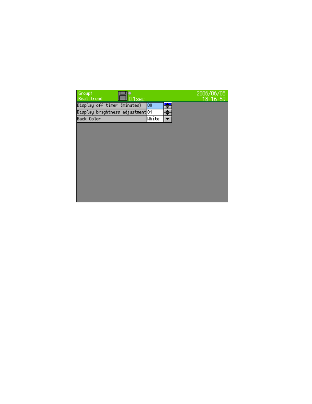
13.3.4 LCD settings
・ Operation is done using MENU settings
・ Move the focus to the setting item using direction key.
・ When ENTER key is clicked for the item to be set one moves to the input screen.
Following screen is displayed when LCD settings of display settings screen is selected from settings
menu screen.
■Setting display off timer (minutes)
・ The period of display off timer of LCD can be set from 1 minute to 60 minutes.
・ For canceling the display off, click any key.
■Setting the ‘display brightness adjustment'
・ Brightness of LCD backlight can be selected from 4 steps.1 is the brightest and 4 is the darkest.
■Setting back color
・ Either white or black is selected as back color of the screen.
- 59 -
Page 65

13.4 Alarm settings
・ Operation is done using MENU settings
・ Move the focus to the setting item using direction key.
・ When ENTER key is clicked for the item to be set one moves to the input screen.
Following screen is displayed when, alarm settings is selected in settings menu screen.
■Setting the type
・ Type of alarm is set.
None Alarm is not set Diff. upper Sets differential upper
limit alarm
Upper Sets upper limit alarm Diff. lower Sets differential lower
limit alarm
Lower Sets lower limit Error Sets error alarm
■Setting the settings value
・ Judgment value of alarm is set.
■Setting reference CH
・ During differential upper limit/differential lower limit, channel No. that becomes the reference, is set.
■Setting dead band
・ Alarm dead band, between alarm value and cancellation is set.
■Setting delay
・ Delay time of alarm is set.(0-3600 seconds)
■Setting relay
*When alarm is outputted actually, alarm output terminal (option) is necessary
・ Regardless of existence of alarm output terminals, setting can be done.
・ Set the alarm output terminal No. 0-12. When alarm output is set to 0, alarm is not outputted.
■Setting alarm output mode
AND Relay is ON when all the alarms set in one alarm output terminal are in alarm status.
OR
Relay is ON when a number of alarm relays are connected to one alarm output
terminal and one among those is in alarm status.
- 60 -
Page 66

Differential alarm
(Differential upper limit alarm)
Alarm value
Differential upper limit alarm activation when, Difference of measurement values (Absolute
value) ≥ alarm value
Differential lower limit alarm activation when, Difference of measurement values (Absolute
value) ≤ alarm value
Alarm dead band
(Absolute value)
Uの計警報値
Difference of
measurement
values
Alarm activation Alarm activation
Differential alarm
(Differential lower limit alarm)
Alarm value
Difference of measurement values
(Absolute value)
Lower limit alarm
Deadband
ON
(Activation)
MIN
Alarm value
Alarm deadband
OFF
(Release)
MAX
(Release)
Upper limit alarm
Deadband
OFF
MIN
Alarm value
ON
(Activation)
MAX
- 61 -
Page 67

13.5 File settings
・ Operation is done using MENU settings
・ Move the focus to the setting item using direction key.
・ When ENTER key is clicked for the item to be set one moves to the input screen.
Following screen is displayed when, file settings in settings menu screen is selected.
Following screen is displayed when ENTER key is clicked, when No. column is selected.
■Setting the recording cycle **
Seconds 0.1 sec, 0.2 sec, 0.5 sec, 1 sec, 2 sec, 3 sec, 5 sec, 10 sec, 15 sec, 20 sec, 30 sec
Minutes 1 min, 2 min, 3 min, 5 min, 10 min, 15 min, 20 min, 30 min, 60 min
** If a recording cycle less than 0.5 seconds is set, recording is done in 3 groups and 12 points for
each group.
■Setting the data format
When recording cycle is 0.1 seconds, only sampling can be selected.
In case of recording the data in the file, average, maximum, minimum, maximum/minimum of the
recording cycle can be recorded. When maximum/minimum is selected, data size becomes 1.5 times
larger.
Sampling Average Maximum Minimum Maximum/minimum
- 62 -
Page 68

■Setting start trigger
Recording is started using the following trigger.
Key Alarm
Trigger
type
Key Starts the recording without conditions
Alarm Starts the recording when alarm relay is ON
Digital
input
■Setting pretrigger (0-1000)
At the time of starting the recording, the data of the count set here is recorded back.
Example: When recording is started at 13:00:00 with pre-trigger “10”, recording cycle “2 seconds”
Note: There are cases when data of the minutes specified here is not sufficient as, in case of power
■Setting end trigger
‘End recording’ condition is selected. First item displays the contents same as that of start trigger.
■Setting save format
File format at the time of recording to CF card is selected.
■Setting the auto save period
It is the period for copying the internal memory file to CF card.
Other than this period, each file is copied to CF card at the time of completion.(Refer to 9.9)
■Setting the directory (Maximum length 16 characters)
・ In case of saving the data to an external storage media, directory name in which it is to be set
can be specified.
・ Hierarchy can also be specified. Delimiting symbol is “\” (backslash).
For input method refer to “7.3 Method of entering the characters”.
(option)
the data from 12:59:40 to 12:59:58 is added at the beginning of the file.
OFF or settings are changed, the data for pre-trigger is cleared. In that case the data of the
saved minutes is added at the beginning of the file.
Key (Alarm) Period
Trigger
type
Key
(Alarm)
Period Stops after recording the data of the specified period (seconds). At that time
Binary CSV
Save
format
Binary Recording is done in binary file (extension “krf”) For replay either this
CSV Recording is done in CSV format text file. It can be read using spreadsheet
Minutes No settings, 1 min, 2 min, 3 min, 5 min, 10 min, 20 min, 30 min, 60 min
Contents
If this item is selected, relay channel can be selected
Start the recording when digital input terminal is ON
If this item is selected, input terminal No. can be selected
(seconds)
Contents
Stops the recording when start condition is not formed.
if the start condition is formed then it immediately (within 1 second) starts
recording.
Contents
instrument or analysis software is necessary.
software like excel (made by Microsoft) etc. It can be used as report
application of attachment.
When decimal point is set as “,”, it becomes a text file with tab delimiter. In
this case the extension is “txt”.
- 63 -
Page 69

13.6 Totalizer reset settings
Totalizer is done by using the calculation settings of each channel. In this screen, a process for resetting
the totalization data to 0, is set.
・ Operation is done using MENU settings
・ Move the focus to the setting item using direction key.
・ When ENTER key is clicked for the item to be set one moves to the input screen.
Following screen is displayed when, totalizer reset settings of settings menu screen is selected.
■Manual reset
• Consider totalization data to be 0.
■Auto reset
• In case of using auto reset of totalizer, switch it ON.
Switch it OFF when it is not in use.
■Standard time, interval
• Totalizer reset is performed at the following time,
Base time + (interval x n) n = 0, 1, 2, 3, … .
Example: When “base time” is 0:00 and “interval” is 04:00, totalization value is reset at
0 o’clock, 4 o’clock, 8 o’clock, 12 o’clock, 16 o’clock and 20 o’clock.
■Digital input reset (option)
• Totalizer is reset is performed when specified digital input terminal is ON.
In case of not using, select “OFF”.
- 64 -
Page 70

13.7 Schedule settings
・ Operation is done using MENU settings
・ Move the focus to the setting item using direction key.
・ When ENTER key is clicked for the item to be set one moves to the input screen.
Following screen is displayed when scale settings from settings menu screen is selected.
If schedule is set in this screen, only that period is recorded. Even though the condition specified in file
settings are formed, only the cases of the schedule period are recorded.
For period other than the schedule period, status bar is displayed in gray color.
■Setting the schedule
• No settings, date and day is selected.
• Due to these settings, the following settings become enabled.
■Parameter of date settings is set.
• Start date and time, and end date and time is set.
■Parameter of day settings is set.
• Usage days is checked.
• Start time and end time is set.
- 65 -
Page 71

13.8 Marker text setting
・ Operation is done using MENU settings
・ Move the focus to the setting item using direction key.
・ When ENTER key is clicked for the item to be set one moves to the input screen.
Following screen is displayed when marker text settings of settings menu screen is selected.
Up to 50 marker texts to be inserted on trend can be registered here, in advance. For marker text writing
refer to chapter 9.3.
Even when it is not registered here, text can be created at the time of marker insertion.
(The maker inserted with digital input (option))
The maker is inserted on trend with ON of the digital input terminal.
<Digital input --- standard>
When the channel that is specified for [digital input] is ON, the corresponded maker is inserted on trend
of specified group.
<Digital input --- binary>
When the contact point state is input in the state of 1-50 and turn ON CH8 with using CH1-7 of digital
input terminal (CH1 side is low order bit and CH4 side is high order bit of binary expression), the marker
which is corresponded with [No.] is inserted on trend of specified group.
Without digital input option
With digital input option
・ If clear is selected marker text is erased.
・ If message column is selected, character input screen is displayed.
- 66 -
Page 72
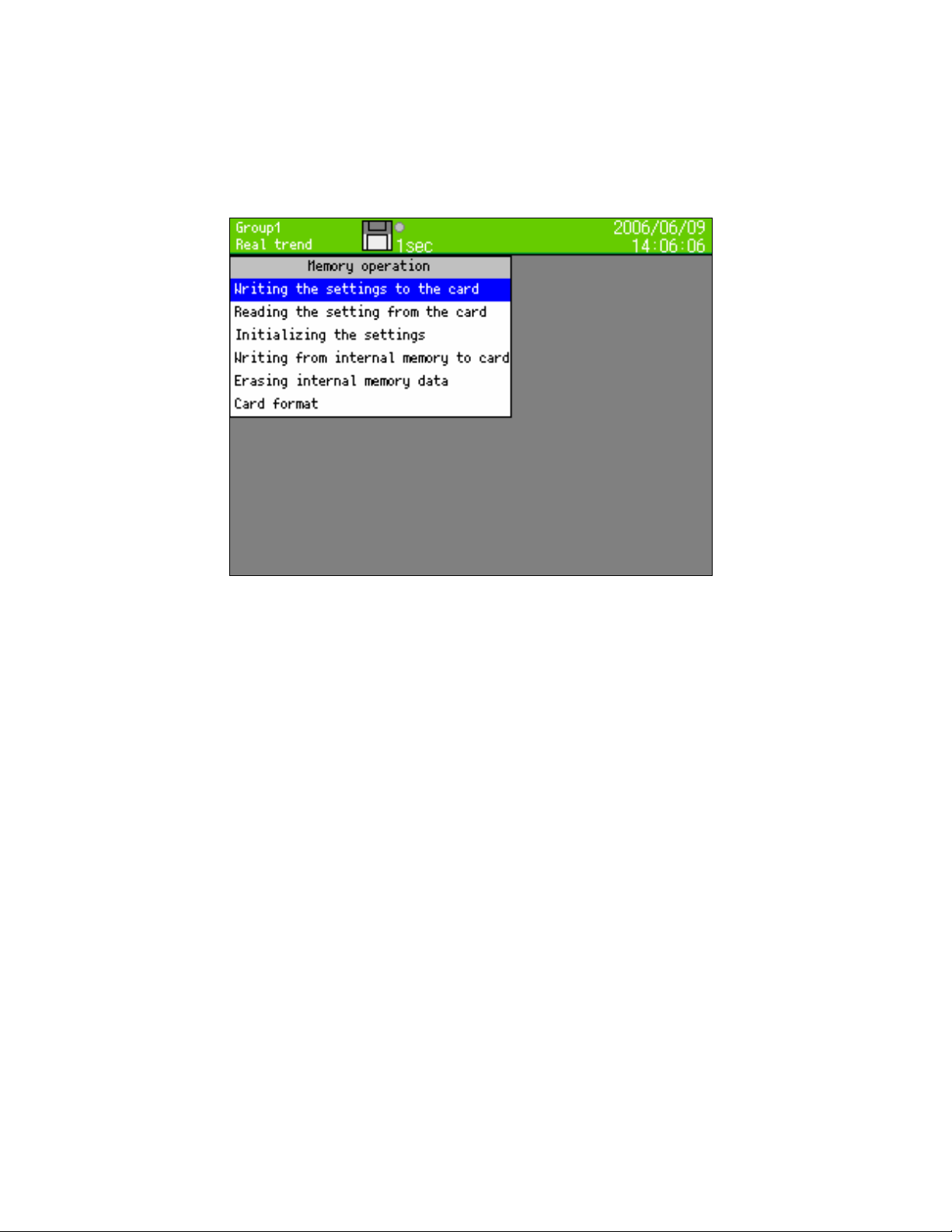
13.9 Memory operation
・ Operation is done using MENU settings
・ Move the focus to the setting item using direction key.
・ When ENTER key is clicked for the item to be set one moves to the input screen.
Following screen is displayed when, memory operation of settings menu screen is selected.
■Writing the settings to the card
Up to 10 current setting contents can be written to CF card.
Numbers 1-10 and file name is displayed as list. Select the number to be written and click the ENTER
key.
On clicking the “ENTER” key after entering the file name, setting contents are written.
File is saved with extension “.krs”, in “SETUP” folder in the CF card.
Settings file can be read and used in other RD9900 series also.
■Reading the settings from card
Settings file is read from CF card and the current settings are overwritten.
Numbers 1-10 and file name is displayed as list. Select the number to be read and click the ENTER
key.
■Initializing the settings
As the current settings are the settings at the time of shipping from the factory they are overwritten.
■Writing the internal memory to card
Entire data from the internal memory is written to the CF card.
■Erasing internal memory data
Entire data of internal memory is erased.
■Card format
CF card is quick formatted.
- 67 -
Page 73

13.10 Network settings
13.10.1 Ethernet settings
・ Operation is done using MENU settings
・ Move the focus to the setting item using direction key.
・ When ENTER key is clicked for the item to be set one moves to the input screen.
Following screen is displayed when Ethernet settings of network settings screen is selected from
settings menu screen.
This instrument performs address settings etc. for using on the Ethernet.
■IP address
Set IP address of this instrument. DHCP (IP address auto acquisition) cannot be used.
Ask the IP address to the administrator of the network to be connected to.
■Subnet mask
Set the subnet mask of this instrument.
■Default gateway
If there is router gateway etc. on the network, set default gateway address.
In case of using in small scale network, set the IP address as follows, using a router, without
connecting to internet and company LAN .
Instrument IP address Subnet mask
RD9900 A 192.168.254.254 255.255.255.0
RD9900 B 192.168.254.253 255.255.255.0
…
PC A 192.168.254.1 255.255.255.0
PC B 192.168.254.2 255.255.255.0
… … …
Example of usage in small scale network
… …
- 68 -
Page 74

13.10.2 FTP server settings
・ Operation is done using MENU settings
・ Move the focus to the setting item using direction key.
・ When ENTER key is clicked for the item to be set one moves to the input screen.
Following screen is displayed when FTP server settings of network settings screen is selected from
settings menu screen.
Settings, for using the FTP server function of this instrument are done.
■FTP server ON/OFF
When ON the FTP server function is executed. Switch it OFF when FTP server function is not in use.
■Login user name
Set the user name for logging in to the FTP server.
■Login password
Set the password for logging in to FTP server.
By using the function of FTP server, file in the CF card of this instrument can be read from the
network PC. Method of connection at the time of using Web browser (InternetExplorer、Netscape、
Opera) is explained below.
Enter “ftp://(IP address of this instrument)/
List of files and folders is displayed in the browser.
And the later operations like moving, copying, opening file etc. are similar to those of windows
In case of connecting using FTP client software other than Web browser, connect by doing the
settings in each of the software such that one can log in using the user name and password set in
this instrument.
Method of using FTP server
Note: In case of connecting to FTP server using Web browser, if user name other than
“anonymous” is set, normal connection may not be possible.
and click the ENTER key of the PC
explorer. However writing to this instrument is not permitted.
- 69 -
Page 75

13.10.3 E-MAIL settings
In this instrument E-MAIL can be sent by alarm or time event.
Specify beforehand the addresses to whom the mail is to be sent and when the event (Maximum 8
conditions can be registered) is activated, the mail is sent to the address that is selected.
・ Operation is done using MENU settings
・ Move the focus to the setting item using direction key.
・ When ENTER key is clicked for the item to be set one moves to the input screen.
Following screen is displayed when E-MAIL settings of network settings screen is selected from settings
menu screen.
When forwarding address is selected, following screen is displayed. (For settings of forwarding address
name, refer to “7.3 Method of entering the characters”.)
Forwarding address is set.
・ Forwarding address up to 8 contacts can be set
- 70 -
Page 76

Following screen is displayed when selecting ‘forwarding condition’ is selected.
■Selecting the condition number
・ Maximum 8 types of E-mail forwarding conditions can be registered. The condition number
selected here, is set in the screen.
■Selecting forwarding condition
・ The condition at which E-MAIL is to be forwarded to forwarding address, is set.
Item Contents
None This condition is not used
Alarm activation
Sends when alarm is activated in the specified channel.
time
Fixed interval Considers the base time as standard and sends E-MAIL at every
interval.
■Setting the beginning CH, ending CH
• Beginning CH and ending CH to be forwarded during alarm activation is set.
■Beginning CH, ending CH
• It is enabled when “Alarm activation time” is selected in forwarding condition.
E-mail is sent when alarm is activated in the specified channels from beginning channel to
ending channel.
■Base time, interval
• E-mail is sent at the following time.
Base time + (interval x n) n = 0, 1, 2, 3, … .
Example: When “Base time” is 0:00, “Interval” is 04:00, E-mail is sent at 0 o’clock, 4 o’clock,
8 o’clock, 12 o’clock, 16 o’clock and 20 o’clock.
■Forwarding address
• Check the address to which E-mail is to be forwarded.
- 71 -
Page 77

Following screen is displayed when ‘Interval forwarding channel’ is selected.
When “fixed interval” is specified in forwarding condition, the data of the channel registered in this screen
is written in the body of the E-mail and it is sent.
■Condition number
・ Select the E-mail forwarding condition number that performs the settings.
■Setting fixed interval forwarding CH data
・ Channel number of the data to be attached is checked
Following screen is displayed when account is selected.
■POP3 address
・ SMTP server is used when POP3 authentication is required. Enter the address of POP3 server.
Do not input anything when POP3 authentication is not required.
■SMTP address
・ Enter the address of SMTP server.
■Sender address
・ Enter the E-mail address obtained for this instrument. If the address is not correct, there also
exist SMTP servers that do not receive the sent mail.
■Account
・ Enter the mail account to be used in mail server login.
■Password
・ Enter the password to be used in mail server login.
- 72 -
Page 78

13.10.4 DNS settings
DNS server is the server for converting the address specified by name, to IP address.
If address of FTP server, POP3 server, SMTP server etc. are entered as names, it is necessary to set the
DNS server.
・ Operation is done using MENU settings
・ Move the focus to the setting item using direction key.
・ When ENTER key is clicked for the item to be set one moves to the input screen.
Following screen is displayed when DNS settings of network settings screen is selected from settings
menu screen.
■DNS on/off
・ DNS ON (enabled), OFF (disabled) is selected
■Primary server IP, secondary server IP
・ Enter the address of DNS server. When primary server is not found, secondary server address is
used. When there is only 1 DNS server, it is okay even if secondary server column is blank.
- 73 -
Page 79

13.11 System settings
13.11.1 Clock settings
Set the date/clock of internal clock of this instrument.
・ Operation is done using MENU settings
・ Move the focus to the setting item using direction key.
・ When ENTER key is clicked for the item to be set one moves to the input screen.
Following screen is displayed when, clock settings of system settings is selected from settings menu
screen.
When year month date, time are selected the following screen is displayed, input in the same way as one
does for character input.
Writing to internal clock is done by clicking “Set” button. Click “Set” button in accordance to the time
signal etc.
For display format select, date display format.
YY/MM/DD: Year/month/date
MM/DD/YY: Month/date/year
DD/MM/YY: Date/month/year
- 74 -
Page 80

13.11.2 Key lock
・ Operation is done using MENU settings
・ Move the focus to the setting item using direction key.
・ When ENTER key is clicked for the item to be set one moves to the input screen.
Following screen is displayed when key lock of system settings is selected from settings menu
screen.
When key lock is ON, and when MENU key or HOME key is clicked, setting screen does not appear
unless password is entered. Set the password using “Password settings” on the next page.
■Setting key lock
・ Set ON/OFF of key lock.
(Message when key lock is ON)
- 75 -
Page 81

13.11.3 Password settings
・ Operation is done using MENU settings
・ Move the focus to the setting item using direction key.
・ When ENTER key is clicked for the item to be set one moves to the input screen.
Following screen is displayed when, password settings of system settings is selected from settings
menu screen.
This password is used
・ When key lock is to be released
・ And in case of login password for displaying the web page
■Setting password (For password name setting, refer to “7.3 Method of entering the characters”.)
・ Password of key lock is set.
■For changing the password
・ The password is changed by entering the currently used password in old password field, enter
the changed password in the new password field.
- 76 -
Page 82

13.11.4 Other settings
・ Operation is done using MENU settings
・ Move the focus to the setting item using direction key.
・ When ENTER key is clicked for the item to be set one moves to the input screen.
Following screen is displayed when other settings of system screen is selected from settings menu
screen.
■Language
・ Language can be selected from English and Japanese. Default setting is English.
■Name of the instrument
・ Used in subject at the time of sending E-mail.” Message from (name of the instrument)” is used
as subject.
・ When blank, it becomes "Message from RD9900"
■Setting usage group count
・ Usage group count can be set from 1-5.
・ The smaller the usage group count the longer the period for recording it in internal memory
(Refer to 9.9 Internal memory).When usage group count is 4 or more, recording within interval of
less than 1 second is not possible.
■Setting the decimal point
・ 2 types of decimal points can be set “. (period)”, “, comma”.
・ When decimal point is a comma and format for saving the file is CSV, file becomes a text file with
tab delimiter (Refer to 13.5 File settings).
■Setting 50Hz/60Hz
・ Power supply frequency can be selected from 50Hz, 60 Hz.
■Setting filter label
• Input filter can be set between 0-3. 0 means no filter and 3 means the strongest filter.
■Setting overwrite mode
• When overwrite mode is ON and the CF card remaining amount decrease, deleting old file and
continuing to insert to CF card. When overwrite is Off and the CF card remaining amount is
insufficient, the data is not inserted any more (recording is continued in internal memory).
- 77 -
Page 83

Setting/Displaying in WEB screen
14
14.1 Display and settings of the Web screen
Inputting the recorder, displaying the data and settings for recording are done using web browser.
14.1.1 Top page
When IP address of recorder is accessed through web browser (Ex: Internet Explorer), the following
screen is displayed after password authentication.
In password authentication the user name to be used is fixed as “user” and it cannot be changed
however, the password can be set and changed for the machine, to an arbitrary string. When link is
clicked, one moves to the following from above, “recorder display” that displays the same screen of the
instrument (RD9900) in browser and can be operated the instrument on this screen, “data display” that
displays the data of each recording channel, “input settings” that sets input parameter for each channel,
“alarm settings” that sets alarm parameters, “calculation settings” that sets operators for each channel
and “group settings” that sets items associated with recording.
- 78 -
Page 84

14.1.2 Recorder display
Display the same screen as the instrument (RD9900). Keys of the screen can be operated same as keys
of the instrument. It will be taken more time for reading than other screen because of using image file. For
preventing operational error, do not operate the screen of the instrument and this recorder display screen
simultaneously.
Do not use ‘refresh’, ‘back’, ‘forward’ etc. in the browser. Use the keys bottom of the screen.
When click the ‘refresh’ key of the right bottom of the screen, performing reload of previous display. When
click ‘auto refresh ON’ key, refresh the screen every 5 seconds. When stop the auto refresh, click ‘auto
refresh OFF’.
14.1.3 Data display
Recorder data displays 44 channels along with tag name and unit. At the time of display, screen can be
selected from, ‘screen that fixed displays the acquired data’ and ‘screen that automatically refreshes the
data after every 5 seconds’. If link is clicked from the TOP page, one moves to the screen that fix displays
the data acquired at the time of displaying. To go to the auto refresh screen, click “Start auto refresh” link
on the lower part of the screen.
- 79 -
Page 85

14.1.4 Input settings
Setting on input parameter of the recorder is changed. When ‘Set’ button is clicked after entering each
item, the setting contents are written in the recorder. Settings of 6 channels is displayed on 1 screen,
channel block to be displayed can be switched by selecting the link from "Display CH selection" table
that is there on the upper part of the screen.
Settings cannot be changed during recording.
Contents of each item to be set
Setting items Contents
Range type Input range is selected.
RJ Reference junction compensation is selected from internal/external
Range Min Minimum value of the range is selected.
Range Max Maximum value of the range is selected.
Scale Min Minimum value of the scale is set.
Scale Max Maximum value of the scale is set.
Burnout Burnout is selected from upper limit, lower limit and none.
Tag Maximum single byte 15 characters are set as tag name for the data.
Unit Unit of data is set in maximum 7 single byte characters.
- 80 -
Page 86

14.1.5 Alarm setting
Setting of alarm parameter of the recorder is changed. When ‘Set’ button is clicked after entering each
item, the setting contents are written in the recorder. Settings of 6 channels is displayed on 1 screen,
channel block to be displayed can be switched by selecting the link from "Display CH selection" table that
is there on the upper part of the screen.
Contents of each setting item
Setting items Contents
Alarm 1-4 Type Type of each alarm can be selected.
Alarm 1-4 setting value Alarm value of each alarm is set.
Alarm 1-4 reference CH
Alarm 1-4 dead band Dead band of each alarm is set.
Alarm 1-4 delay Delay of each alarm is set from 1-3600 seconds.
Alarm 1-4 relay number
Alarm 1-4 AND/OR
If differential alarm is set in alarm kind of each alarm, comparison
channel is selected.
Output destination relay number at the time of activating the
alarm, is selected.
Whether to output by getting AND or whether to output by getting
OR of the specified channel, is set during each alarm activation.
- 81 -
Page 87

14.1.6 Calculation settings
Whether to use/not the calculation for each channel of recorder is selected and arithmetic expression is
set. When ‘Set’ button is clicked after entering each item, the setting contents are written in the recorder.
Settings cannot be changed during recording.
Contents of each setting item
Setting items Contents
Calculate Whether to use the calculation or not is selected.
Formula Calculation contents are set in a string of maximum 48 characters.
- 82 -
Page 88

14.1.7 Group settings
Settings of parameters associated with the recording of the recorder are changed. When ‘Set’ button is
clicked after entering each item, the setting contents are written in the recorder. Settings of 1 group are
displayed on 1 screen, group to be displayed can be switched by selecting the link from "Group number"
table that is there on the upper part of the screen. The group that can be selected here is each group
from group 1 to the usage group count that is set in “System settings” → “Other settings” of the recorder.
During recording when recording ON is selected the group that is set cannot be changed.
Contents of each setting item
Setting items Contents
Group name Group name can be set by a string of maximum 16 characters.
Recording cycle Time interval to display and record the data is selected.
Recording ON/OFF Whether to select a relevant group or not is selected.
Input channel
Trend display
Input channel number to be recorded in the each recording
channel is selected.
Whether to display or not on the screen the trend of each recording
channel is selected.
- 83 -
Page 89

14.1.8 Maker text setting
Setting of maker text parameter of the recorder is changed. When ‘Set’ button is clicked after entering
each item, the setting contents are written in the recorder. After setting text of the end (No.10 in below the
figure), 10 more texts are displayed, and text can be set maximum 50.
Refer to 9.3 and 9.6 about maker insertion in trend.
Contents of each setting item
Setting item Contents
Text (No. 01 to 50) Maker text can be set by a string of maximum 30 characters.
- 84 -
Page 90

15
Read the recorded data using USB
15.1 Outline
The recorded data stored in the CF card can be read through USB port installed in RD9900. Therefore,
the required file can be copied to the PC without removing the CF card from the instrument.
15.2 Operation Environment
Compatible PC
Compatible OS Windows2000 / XP
Compatible USB cable A type plug-B type plug
Limitations
Model loaded with USB1.1 or higher interface
Operations by connecting via USB hub are not guaranteed.
Write operations to file or folder (Including Move, name change) are
not possible.
CF card is not recognized depend on the USB port of your personal
computer.
Please acknowledge not supporting it in that case.
15.3 Access to data file
Check that the CF card is inserted when RD9900 is in operating condition.
Open the front compartment and connect the USB port of the PC on which USB port of RD9900 and OS
are being installed, with the compatible USB cable.
After connecting, CF card set in RD9900 is recognized as the removable disk on the OS. (Drive is
automatically installed when connected with the PC initially. Restarting of OS is requested depending on
the PC environment.)
Removable disk added by USB
connection. CF card in
RD9900 can be assessed.
Contents of the CF card set in RD9900 can be read by accessing the recognized removable disk.
Since it is a read-only file, copy the required file to the hard disk in the PC and then use it.
- 85 -
Page 91

¢ Do not disconnect the power supply when the data is being accessed.
Take care as the contents of the CF card may get destroyed and the data may get lost,
when the power supply of RD9900 is disconnected, when the data file is being accessed.
¢ Do not remove the USB cable when the data is being accessed.
Operations of RD9900 system may get unstable on removing the USB cable, when the
data file is being accessed. Moreover, in case to remove the cable, click on “Safe
Removal of Hardware” icon displayed on the task tray on the PC screen and then
execute the operations stipulated by OS.
¢ Access to the data when it is being recorded
RD9900 system executes the access to the CF card when the storing operation is in
progress. Although it can operate exclusively by the access from the PC, however, as the
total performance decreases, access the data when the storing operation is being
stopped,
¢ Update card information
After connecting the cable, the file on the updated CF card may not be displayed on the
PC. When recording operation, write of setup file, snapshot is executed after connecting
the cable, file information is updated by inserting and removing the CF card.
Warning
- 86 -
Page 92

16
Scale calibration
16.1 Scale calibration
To maintain the measuring accuracy, it is recommended to calibrate this instrument every year.
Calibration Name Description
Zero-span
adjustment
※ Setting sensor correction (shift of value) for each channel is available.(Refer to 13.2 Input
operation settings)
Adjustment by entering the zero and span of measuring range for each.
*This instrument dose the input processes with 1 AD converter every 4
channels. Therefore, 6 point specification adjust 2 times and 12 point
specification adjust 3 times with inputting the zero and span of each
measuring range.
16.2 Calibration Environment
Items Reference conditions
Ambient temperature 23ºC ± 2ºC
Ambient humidity 50% ± 10%
Power voltage 100V AC ± 1%
Power frequency 50Hz or 60Hz ± 0.5%
16.3 Preparation
16.3.1 Preparation of tools
Input types
Tools
DC voltage current
generator
Reference junction
compensator
Thermocouple for
test
Standard variable
resistor
3-core copper wire
DC
voltage
Ο
Thermocouple Resistance
Accuracy: Shell be better than
Ο
Ο
Ο
Ο
±0.05%
ºC ± 0.2ºC
0
Same type of thermocouple as
input type
Accuracy: Shell be better than
±0.05%
Three copper wires shall have
the same resistance value
16.3.2 Before calibration
① Attach the terminal board cover and turn power on.
② Keep the RD9900 series graphic recorder’s power on for more than 30 minutes until it is stabilize.
(The ideal warm-up period is more than 1 hour.)
Remarks
Checking and adjustment of measured values require careful work with a standard tool and other tools.
When checking an adjustment of measured values are required, please contact our sales agent.
Adjustment
Remarks
- 87 -
Page 93

16.4 Connection
Connections depend upon the input types.
Connect a standard tool and other tools to the measuring input terminals to be adjusted.
■Turn off the source power supply before starting connection
Turn off the source power supply before starting connections for the purpose of preventing an
electric shock accident
Caution
In case of DC voltage input
①
CH2, CH5, CH11 are for adjustment channels.
(+)
When adjustment, connect the CH2、CH5、CH11
like right figure at same time.
CH1-CH4 are adjusted by adjustment of CH2
CH5-CH8 are adjusted by adjustment of CH5
CH9-CH12 are adjusted by adjustment of CH11
■Using only CH2,CH5 for 6 channel
specification
(-)
Input terminals
DC standard voltage generator
② In case of resistance thermometer input
CH2, CH5, CH11 are for adjustment channels.
When adjustment, connect the each channel of CH2、
CH5、CH11 like right figure.
CH1-CH4 are adjusted by adjustment of CH2
CH5-CH8 are adjusted by adjustment of CH5
CH9-CH12 are adjusted by adjustment of CH11
■Using only CH2,CH5 for 6 channel
specification
③ In case of thermocouple input
Ch2, CH5, CH11 are for adjustment channels.
When adjustment, connect the each channel of CH2,
■CH1,CH6,CH12 are used for adjusting three
※ 端子部の温度を測定するための素子が3箇所あり、
それらの調整にCH1、CH6、CH12を使用します。
places of element device for measuring terminal
※ 6チャンネル仕様の場合は、CH1、CH6のみを
temperature.
使用します。
■Using only CH1,CH6 for 6 channel specification
(+)
(-)
Input terminals
Standard variable resistor
CH5, CH11 like right figure.
Thermocouple wire*
(+)
(-)
Input terminals
Ice + distilled water
Vacuum bottle
Test tube
Silicon oil
Reference junction compensator
The electromotive force of the thermocouple input becomes small by the electromotive force equivalent
to the temperature at terminals. The instrument itself compensates for the electromotive force equivalent
to the temperature at terminals. This is called reference junction compensation. Accordingly, the
reference junction compensator is necessary for reducing the electromotive force compensated.
- 88 -
Page 94

16.5 Zero and span adjustment
16.5.1 Calibration menu
・The zero and span adjustment are to be performed by entering the zero and span values of input
range to each channel for adjustment.
・Move the focus to adjusting range by direction key.
・When click the enter key in adjusting range, display the calibration mode.
After clicking MENU key in operation screen, hold the HOME key for more than 5 seconds to display the
calibration menu like below.
The below data show adjusted AD account value.
16.5.2 Adjustment of DC voltage input range
Connect like “16.4 Connection ① In case of DC voltage input”.
Connect CH2, CH5, CH11 at same time, and input the voltage of adjusting range for adjustment.
① Select Go of adjusting range and click the ENTER key.
- 89 -
Page 95

② The window which is indicate input voltage value is shown, then input the voltage value to the
instrument.
③ Adjust zero
Example)In case of adjust ±2V range
・Input 0V by DC standard voltage generator
④ After inputting Zero for more than 5 seconds, click the ENTER key.
⑤ Adjust span
Example)In case of adjust ±2V range
・Input +2V by DC standard voltage generator
⑥ After inputting Span for more than 5 seconds, click the ENTER key.
⑦ After adjusting span, return to calibration menu for all rages.
⑧ In case of adjusting other range, repeat ① to ⑥.
⑨ After adjustment, click the ESC key for retuning MENU settings menu screen.
- 90 -
Page 96
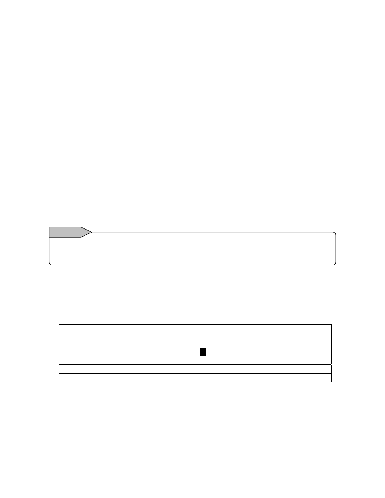
16.5.3 Adjustment of resistance thermometer input range
Connect like “16.4 Connection ② In case of resistance thermometer input”. Input resistance of adjusting
range to each channel of CH2, CH5, CH11 for adjustment.
① Select Go of adjusting range, and click the ENTER key.
② The window which is indicate input resistance value is shown, then input the resistance value to the
instrument.
③ Adjust zero
Example)In case of adjusting Pt150 range
・Input 100Ω by standard variable resistor
④ After inputting Zero for more than 5 seconds, click the ENTER key.
⑤ Adjust span
Example)In case of adjusting Pt150 range
・Input 157.33Ω by standard variable resistor
⑥ After inputting Span for more than 5 seconds, click the ENTER key.
⑦ After adjusting span, return to calibration menu for all rages.
⑧ In case of adjusting other range, repeat ① to ⑥.
⑨ After adjustment, each channel of CH2, CH5, CH11, click the ESC key for retuning settings menu
screen. When adjust channel is opening, not adjusted that channel.
16.5.4 Adjustment of thermocouple input range…Adjustment of reference junction (RJ0ºC)
Remarks
After adjusting DC voltage input range, adjusting thermocouple input range. If adjusting DC voltage
input range after adjusting thermocouple input range, result of adjustment is influenced.
Connect like “16.4 connection ③ In case of thermocouple input”.
Connect thermocouple to each CH1, CH6, CH12 for adjustment.
① Before moving calibration screen, set input setting of CH1, CH6, CH12 like below.
(Refer to “13.2.1
Range type Connecting thermocouple
Range
RJ
Burnout
Setting contents”)
Set 1 for decimal point position of range setting value.
Recommend:Reference range ±13.8mV、Display resolution 0.1℃ for
Measuring range(Refer to “18 Specifications 〇 Measuring Range,
Accuracy Rating and Display Resolution”)
Internal
None
- 91 -
Page 97

② Select Go of range RJ0ºC in calibration screen, and click ENTER key.
③ After 30 seconds elapsing, click the ENTER key.
④ After adjusting span, return to calibration menu for all rages.
⑤ After adjustment, click the ESC key for retuning MENU settings menu screen.
Remarks
■ When mistake inputting the value and some inconvenience occurs, try to adjust again.
■ When select CLR and click ENTER key in the adjustment screen, adjustment data is cleared
and is returned to the original data at the time of shipping from factory.
- 92 -
Page 98

Recommended parts replacement
17
interval
It is recommended to replace parts periodically as preventive maintenance for using this instrument under
good conditions for a long time
For replacement of parts, always have OMEGA-approved service personnel perform the operation.
Otherwise, this instrument may not recover properly and also accident may occur. Ask OMEGA sales
agent to perform parts replacement.
17.1 Operating Conditions
The reference parts exchange intervals are under the following standard conditions. The intervals become
shorter if the surrounding conditions are worse than the standard conditions.
Items Conditions Items Conditions
Temperature
Humidity 20 to 80%RH
Operation
time
Corrosive
gas
17.2 Reference of Parts Replacement Intervals
Power supply unit 5 years
LCD 3 years
Keypad 5 years
Relay (For mechanical
alarm output)
Lithium battery 5 years
** The exchange interval of the LCD is, the interval when the brightness reduces to half. The brightness
reduction differs depending on the usage status.
The replacement interval extends by using the screen saver function and by reducing the brightness.
20 to 25°C
8 hours/day
Shall be free of
corrosive gases
Part name
70,000 times
20,000 times
Exchange
reference
Warning
1) A place free of dust, moisture,
and soot
Others
Surrounding temperature 25°C
ø
Resistance load
(Less than rated contact rating)
Inductive load
(Less than rated contact rating)
2) A place free of vibrations and
shocks
3) A place where operation is not
affected unfavorably
Remarks
- 93 -
Page 99

Specifications
18
■General Specifications
Rated power voltage: 100-240 VAC,50/60 Hz
Power consumption: 50VA MAX
Operating conditions:
・ Reference operating condition
… Ambient temperature/humidity range
21 to 25ºC 45 to 65%RH
Power voltage 100 VAC ±1%
Power frequency 50/60 Hz ±0.5%
Attitude left/right 0° forward tilting 0° backward
Warm-up time: 30 minutes or more
Normal operating condition
… Ambient temperature/humidity range
0 to 50ºC, 20 to 80%RH
Power voltage 90 to 264 VAC
Power frequency 50/60 Hz ±2%
Attitude left/right 0° forward tilting 0°
・Transportation condition,
… In the packed condition on shipment from the factory
Ambient temperature/humidity range
-20 to +60ºC, 5 to 90%RH (no dew condensation)
Vibrations 10 to 60 Hz, less than 0.5 G
・Storage condition,
… Ambient temperature/humidity range
-20 to 60ºC, 5 to 90% RH (no dew condensation)
Power failure protection:
FLASH memory and SRAM stores the setting.
A FLASH memory stores the data.
A lithium battery backs ups the clock and parameter
RAM for more than 5 years (provided that the daily
operating hours is longer than 8 hours).
Insulation resistance:
Between secondary and protective conductor terminals
Between primary and protective conductor terminals
Between primary and secondary terminals
Between alarm output (mechanical relay) and other
secondary terminal
Primary terminals: Power terminals (L, N),
Dielectric strength:
Between secondary and protective conductor terminals
Between primary and protective conductor terminals
Between primary and secondary terminals
Case assembly material: Door flame……ABS resin
Color: Door frame…… Black (Equivalent to Munsell N3.0),
Weight: Approx. 2.2 kg
Mounting: Panel mounting
Clock accuracy: ±2 minutes per 30 days (excluding errors
due to power ON/OFF under the reference operating
conditions.)
Secondary terminals: Input terminals,
Primary terminals: Power terminals (L, N),
Secondary terminals: Input terminals,
Case……Gray (Equivalent to Munsell N7.0)
(Universal power supply)
tilting 0°
backward tilting 0° to 20°
Impact Less than 40 G
…… More than 20 MΩ at 500 VDC
…… More than 20 MΩ at 500 V DC
…… More than 20 MΩ at 500 VDC
…… More than 20 MΩ at 500 VDC
…… 1 minute at 500 V AC
…… 1 minute at 1500 V AC
…… 1 minute at 2300 V AC
Case and power supply material…… Steel
Terminal screws:Power terminal ……M4.0
Protective conductor terminal ……M4.0
Input terminals ……M3.5
Alarm output terminals ……M3.5
Digital input terminal……M3.5
Communication terminals ……M4.0
■ Standards
CE marking: EN61326+A1 Class A
EN61000-3-2+A14,
EN61000-3-3,
En61010-1+A2
(Approval pending)
IP: IEC529 IP54 (front part) compliance (Approval pending)
■ Input Specifications
Measuring points: KR2160… 6 points,
Input types: Universal
DC voltage … ±13.8 mV, ±27.6 mV,
±69.0 mV, ±200 mV,
±500 mV, ±2V, ±5V
±10V
(ø With built-in shunt resistors)
DC current … Available by adding external shunt resistor
T/C… B, R, S, K, E, J, T, N,
NiMo-Ni, CR-AuFe,
PtRh40-PtRh20,
WRe5-WRe26, W-WRe26,
Platinel II, U, L
RTD… Pt100,
JPt100, Pt50, Pt-Co
Range setup: Setting of input types and ranges by key
Scale setup: Setting of minimum values, maximum values
Accuracy rating: See table of inputs.
Temperature drift: ±0.01% of full scale/ ºC [Other input types
Sampling rate: KR2160…0.1 second / 6 points
Reference junction (RJ) compensation accuracy:
(The above errors are added to the accuracy ratings for the
internal reference junction compensation)
Input resolution: Approx. 1/32,000 (converted into reference
range)
Burnout: Signal disconnection detection for thermocouple and
Allowable signal source resistance:
K, E, J, T, N,Platinel II … Maximum ±0.5ºC
resistance thermometer inputs.
Up-scale burnout, down-scale burnout or burnout
disabled can be selected for each input.
Thermocouple inputs (burnout disabled), DC voltage
inputs (max. ±2 V) ….. Less than1 KΩ
DC voltage inputs (±5 to 50 V) ...Less than 100 Ω
Resistance thermometer inputs (Pt100, JPt100)
KR2120…12 points
ø
ø
, ±20Vø, ±50Vø
operation.
The measuring range is selected automatically
according to the set range.
and engineering units by key operation.
than the resistance thermometer inputs are
converted into the reference range (see the
Accuracy Rating table)]
KR2120… 0.1 seconds / 12 points
R,S,NiMo-Ni
CR-AuFe
WRe5-WRe26,
W-WRe26, U, L …… Maximum ±1.0ºC
… Less than10 Ω per wire -- common for 3 wires
,
- 94 -
Page 100

Input resistance: Thermocouple input
DC voltage input
… Approx. 1 MΩ at less than ±2 V,
Maximum input voltage:
Thermocouple inputs (burnout disabled),
DC voltage inputs (max. ±2V) Maximum ±10V DC
DC voltage inputs (±5 to 50 V) Maximum ±60V DC
Thermocouple inputs (burnout enabled),
resistance thermometer inputs Maximum ±60V DC
Maximum common mode voltage: 30V AC
Common mode rejection ratio: Minimum 120dB (50 or 60Hz)
Series mode rejection ratio: Minimum 50dB (50 or 60Hz)
However, when it contains a thing for the signal and the
peak value of the noise is equal to or less than 1.5 times
the standard range.
… Approx. 1 MΩ
■Recording Specifications
Internal memory: 4MB
Recording cycle:
Second 0.1, 0.2, 0.5, 1, 2, 3, 5, 10, 15, 20, 30 sec
Minute 1, 2, 3, 5, 10, 15, 20, 30, 60 min
Recording data:
Measured data (simultaneous storage of max. 5 files)
・Measured data
Group name, recording start date/time, recording cycle,
measured data, alarm data, maker text
・Programmed parameters All parameters
Recording measured data: 4-byte binary/1 data
(Recording maximum and minimum value 6 byte/1 data)
Recoding into internal memory:
:*The following conditions can be selected.
・Key operations
・Trigger signals (alarm activation)
・Start/end by day and time
*Pre-triggering recording available with the key operations
and trigger signals
Pre-triggering measuring count =950 data
*Recording cycle can be programmed for each file
Memory usage display:
The amount of memory used in each file is displayed on
the operation screens by icon.
External memory:・CF card
(FAT16, FAT32 formatted)
■Display Specifications
Display: 5.6-inch TFT color LCD
(316x234 dots: 111.36mmX83.52mm)
Trend display colors: 12 colors (selectable)
Operation screens:
Screens are switched with the DISP. Key, scroll key and
ENTER key.
Screens of 5 groups can be switched except for the
Alarm Summary screen (max. 44 channels/1 group).
・Trend screens:
One of the Real-time Trend, Historical Trend or Dual
Trend displays can be selected.
(scale plate and pointer displays) Vertical or horizontal
orientation selectable. Data display enabled or disabled
selectable. Scrolling available.
・Bar graph screen…Data display enabled or disabled
・Data screen… (Data + Tag + Engineering unit + Alarm
selectable.
activated status)
Alarm summary screen: Current alarm output status + alarm
Skipping: On the Trend and Data screens, the channels to be
Scrolling: On the Historical Trend screens, previous data can
・Historical Trend…Entire Memory file area
・Dual Trend…Enables on the historical trend screen only.
Display (Historical Trend): Historical data is displayed by
* Display by scrolling or by time specified.
* Enables to display from a CF memory card.
Data search (Historical Trend):
Marker display: Marker can be displayed on the real-trend
skipped in display can be set for each group.
be referred with the cursor operation.
Historical trend display by selecting from alarm
display, marker list
screen by the key operation or by digital input
and stored in a message data file.
ø Pre-registration of marker text
(Maximum 50 texts, Maximum 30 characters / Text).
Display updating interval: Same as storing interval
LCD saver: When no key is operated for the specified
period of time, the back-light is OFF. The
period can be set from 1-60 minutes..
log (Channel, level, alarm event
time)
specifying a file.
Data logging is continued.
■Programming/Operation Specifications
Key types: 14
START, STOP, SCROLL, CURSOR, MARKER, DISP, HOME,
MENU, ESC, ENTER,
Direction key: right, left, up, down
HOME setting:
Input parameter setting
Storage interval setting
Specifications confirmation
MENU setting:
Input and arithmetic setting
Display setting
Alarm setting
File setting
Totalizer reset setting
Schedule setting
Marker text setting
Memory operation
Network setting
System setting
■ Alarm Specifications
Number of alarms that can be set: Up to 4 alarms/channel
Alarm types: Upper limit, lower limit, differential higher limit,
Alarm memory: Stores alarm event/cancellation time, alarm
* Storage of latest 200 common channels
Alarm output (Option): 12 points
differential lower limit
types
- 95 -
 Loading...