

Page 1

User’s Guide
http://www.omega.com
e-mail: info@omega.com
R D 2 6 0 A - S 4
RS422A Communications
I n s t ruction Manual
Page 2

OMEGAne t®On-Line Service Internet e-mail
h t t p : / / w w w.omega.com i n f o @ o m e g a . c o m
Servicing North America:
USA: One Omega Drive, Box 4047
ISO 9001 Certified Stamford, CT 06907-0047
Tel: (203) 359-1660 FAX: (203) 359-7700
e-mail: info@omega.com
Canada: 976 Bergar
Laval (Quebec) H7L 5A1
Tel: (514) 856-6928 FAX: (514) 856-6886
e-mail: info@omega.ca
For immediate technical or application assistance:
USA and Canada: Sales Service: 1-800-826-6342 / 1-800-TC-OMEGA
Customer Service: 1-800-622-2378 / 1-800-622-BEST
Engineering Service: 1-800-872-9436 / 1-800-USA-WHEN
TELEX: 996404 EASYLINK: 62968934 CABLE: OMEGA
Mexico and
Latin America: Tel: (001) 800-826-6342 FAX: (001) 203-359-7807
En Espan˜ol: (001) 203-359-7803 e-mail: espanol@omega.com
SM
SM
SM
Servicing Europe:
Benelux: Postbus 8034, 1180 LAAmstelveen, The Netherlands
Tel: (31) 20 6418405 FAX: (31) 20 6434643
Toll Free in Benelux: 0800 0993344
e-mail: nl@omega.com
Czech Republic: ul. Rude armady 1868, 733 01 Karvina-Hranice
Tel: 420 (69) 6311 8 9 9 FAX: 420 (69) 631111 4
Toll Free: 0800-1-66342 e-mail: czech@omega.com
France: 9, rue Denis Papin, 78190 Trappes
Tel: (33) 130-621-400 FAX: (33) 130-699-120
Toll Free in France: 0800-4-06342
e-mail: france@omega.com
Germany/Austria: Daimlerstrasse 26, D-75392 Deckenpfronn, Germany
Tel: 49 (07056) 3017 FAX: 49 (07056) 8540
Toll Free in Germany: 0130 11 21 66
e-mail: info@omega.de
United Kingdom: One Omega Drive, River Bend Technology Centre
ISO 9002 Cert i f i e d Northbank, Irlam, Manchester
M44 5EX, United Kingdom
Tel: +44 (0) 161 777-6611 FAX: +44 (0) 161 777-6622
Toll Free in United Kingdom: 0800-488-488
e-mail: info@omega.co.uk
It is the policy of OMEGA to comply with all worldwide safety and EMC/EMI regulations that
a p p l y. OMEGA is constantly pursuing certification of its products to the European New Appro a c h
D i rectives. OMEGA will add the CE mark to every appropriate device upon cert i f i c a t i o n .
The information contained in this document is believed to be correct, but OMEGA Engineering, Inc. accepts
no liability for any errors it contains, and reserves the right to alter specifications without notice.
WARNING: These products are not designed for use in, and should not be used for, patient-connected applications.
Page 3

Chapter 1 Chapter 2 Chapter 3 Chapter 4 Chapter 5 Chapter 6 Chapter 7
INTRODUCTION
This Instruction Manual describes the option RS-422-A for the RD260A pen and dot
printing recorder.
For details concerning the operation of this recorder, see the instruction manual.
NOTES • OMEGA reserves the right to change this manual at any time without notice.
• If you find any ambiguities or errors in this manual, please inform OMEGA
• PC 9801 is a registered trademark of NEC Corporation.
• IBM is a registered trademark of International Business Machines Corporation.
1
Page 4

CONTENTS
1 INSTALLATION OF RS-422-A INTERFACE
2 RECEIVING FUNCTIONS
INTRODUCTION
1.1 Interface Functions................................................................................................. 1 - 1
1.2 Interface Terminal................................................................................................... 1 - 2
1.2.1 Terminal Arrangement........................................................................................ 1 - 2
1.2.2 Cable Termination .............................................................................................. 1 - 2
1.3 Communication Wiring.......................................................................................... 1 - 3
1.4 Data Configuration ................................................................................................. 1 - 4
1.4.1 Start-Stop Communication ................................................................................. 1 - 4
1.4.2 Text .................................................................................................................... 1 - 4
1.4.3 Input Buffer......................................................................................................... 1 - 5
1.4.4 Buffer Overflow................................................................................................... 1 - 5
1.5 How to Set the RS-422-A Interface Communications ............................... 1 - 6
2.1 Program Set Commands ..................................................................................... 2 - 1
2.1.1 List of Program Set Commands ......................................................................... 2 - 2
2.1.2 Range Setting..................................................................................................... 2 - 3
2.1.3 Offsets Setting.................................................................................................... 2 - 5
2.1.4 Alarm Setting...................................................................................................... 2 - 5
2.1.5 Unit Setting......................................................................................................... 2 - 5
2.1.6 Chart Speed Setting ........................................................................................... 2 - 5
2.1.7 Clock Setting ...................................................................................................... 2 - 6
2.1.8 Trend Recording Format Setting ........................................................................ 2 - 6
2.1.9 Zone Recording Setting...................................................................................... 2 - 6
2.1.10 Partial Expanded Recording Setting .................................................................. 2 - 6
2.1.11 Tag Setting ......................................................................................................... 2 - 6
2.1.12 Message Setting................................................................................................. 2 - 7
2.1.13 Chart Speed 2 Setting ........................................................................................ 2 - 7
2.1.14 Key Lock Setting ................................................................................................ 2 - 7
2.2 Program Control Commands.............................................................................. 2 - 8
2.2.1 List of Program Control Commands ................................................................... 2 - 8
2.2.2 Start/Stop the Recording .................................................................................... 2 - 8
2.2.3 Manual Printout Start/Stop ................................................................................. 2 - 8
2.2.4 List Printout Start/Stop ....................................................................................... 2 - 8
2.2.5 Message Printout Start....................................................................................... 2 - 8
2.2.6 Returning Display to OPERATION Mode........................................................... 2 - 9
2.2.7 Designation Sequence of Byte Output (Binary output)....................................... 2 - 9
2.2.8 Selection of Output Data .................................................................................... 2 - 9
2.2.9 Selection of Output Format for Measured Data.................................................. 2 - 9
2.2.10 Selection of Output Format for Unit/Decimal Point Information.......................... 2 - 9
2.3 Escape Sequence .................................................................................................. 2 - 10
2.3.1 Execution of Trigger ........................................................................................... 2 - 10
2.3.2 Status Output ..................................................................................................... 2 - 10
2.3.3 Open Command ................................................................................................. 2 - 11
2.3.4 Close Command................................................................................................. 2 - 11
3 TRANSMITTING FUNCTIONS
3.1 Introduction to Output Data Formats ............................................................... 3 - 1
3.1.1 TS0..................................................................................................................... 3 - 1
3.1.2 TS1, TS2 ............................................................................................................ 3 - 1
3.2 Output Data Formats ............................................................................................. 3 - 2
3.2.1 Output Format of Measured Values in the ASCII Mode ..................................... 3 - 2
3.2.2 Output Format of Measured Values in the Binary Mode .................................... 3 - 3
3.2.3 Output Format of Setting Parameters ................................................................ 3 - 4
3.2.4 Output Format of Information on Unit and Decimal Point................................... 3 - 4
3.3 Status Byte Format ................................................................................................ 3 - 5
2
Page 5

Chapter 1 Chapter 2 Chapter 3 Chapter 4 Chapter 5 Chapter 6 Chapter 7
4 TIME CHART
5 INITIAL STATUS
6 ERRORS DURING RS-422-A OUTPUT
6.1 Preventing Errors.................................................................................................... 6 - 1
6.2 How to Request for Error Message Output................................................... 6 - 2
6.3 Timing of Resetting Error Status....................................................................... 6 - 2
7 SAMPLE PROGRAMS
7.1 Sample Programs for NEC PC 9801............................................................... 7 - 1
7.1.1 Program to Read Information on Unit and Decimal Point from the recorder,
Display on Screen and Write to Disc (Dot-printing model) ................................. 7 - 1
7.1.2 Program to Output Measured Data (ASCII code) from the recorder and
Write to Disc (Dot-printing model) ...................................................................... 7 - 1
7.1.3 Program to Output Measured Data (Binary code) from the recorder and
Write to Disc (Dot-printing model) ...................................................................... 7 - 2
7.2 Sample Programs for YEWMAC....................................................................... 7 - 3
7.2.1 Program to Read Information on Unit and Decimal Point from the recorder
and Display on Screen (Dot-printing model) ...................................................... 7 - 3
7.2.2 Program to Output Measured Data (ASCII code) from the recorder
and Display on Screen (Dot-printing model) ...................................................... 7 - 3
7.2.3 Program to Output Measured Data (Binary code) from the recorder
and Display on Screen (Dot-printing model) ...................................................... 7 - 4
7.3 Sample Programs for IBM PC............................................................................ 7 - 5
7.3.1 Program to Read Information on Unit and Decimal Point from the recorder,
Display on Screen and Write to Disc (Dot-printing model) ................................. 7 - 5
7.3.2 Program to Output Measured Data (ASCII code) from the recorder and
Write to Disc (Dot-printing model) ...................................................................... 7 - 5
7.3.3 Program to Output Measured Data (Binary code) from the recorder and
Write to Disc (Dot-printing model) ...................................................................... 7 - 6
3
Page 6

1.1 Interface Functions
1
INSTALLATION OF RS-422-A INTERFACE
The -S4 option includes EIA (Electronic Industries Association) RS-422-A communications interface to output measured values and change settting parameters. However, this
interface does not include operations of the power switch and chart feed. Setting of SET
UP mode can not be controlled.
1.1 Interface Functions
Communication system: 4 wire half-duplex multi-drop connection
1:n (host computer: this recorder)
n=1 to 16
Start-stop system
Transmission speeds: 75, 150, 300, 600, 1200, 2400, 4800 and 9600
bits/second
Start bit: 1 bit
Stop bit: 1 or 2 bits
Parity: Even, odd or no parity
Word length: 7 or 8 bits
Electrical signal characteristics: EIA-standard electrical characteristics for the
interchange signals and associated circuitry.
Functional isolation.
Communication distance: Up to 500 meter (between an isolated line converter
or an isolated computer and this recorder)
1 INSTALLATION OF RS-422-A INTERFACE
1 - 1
Page 7
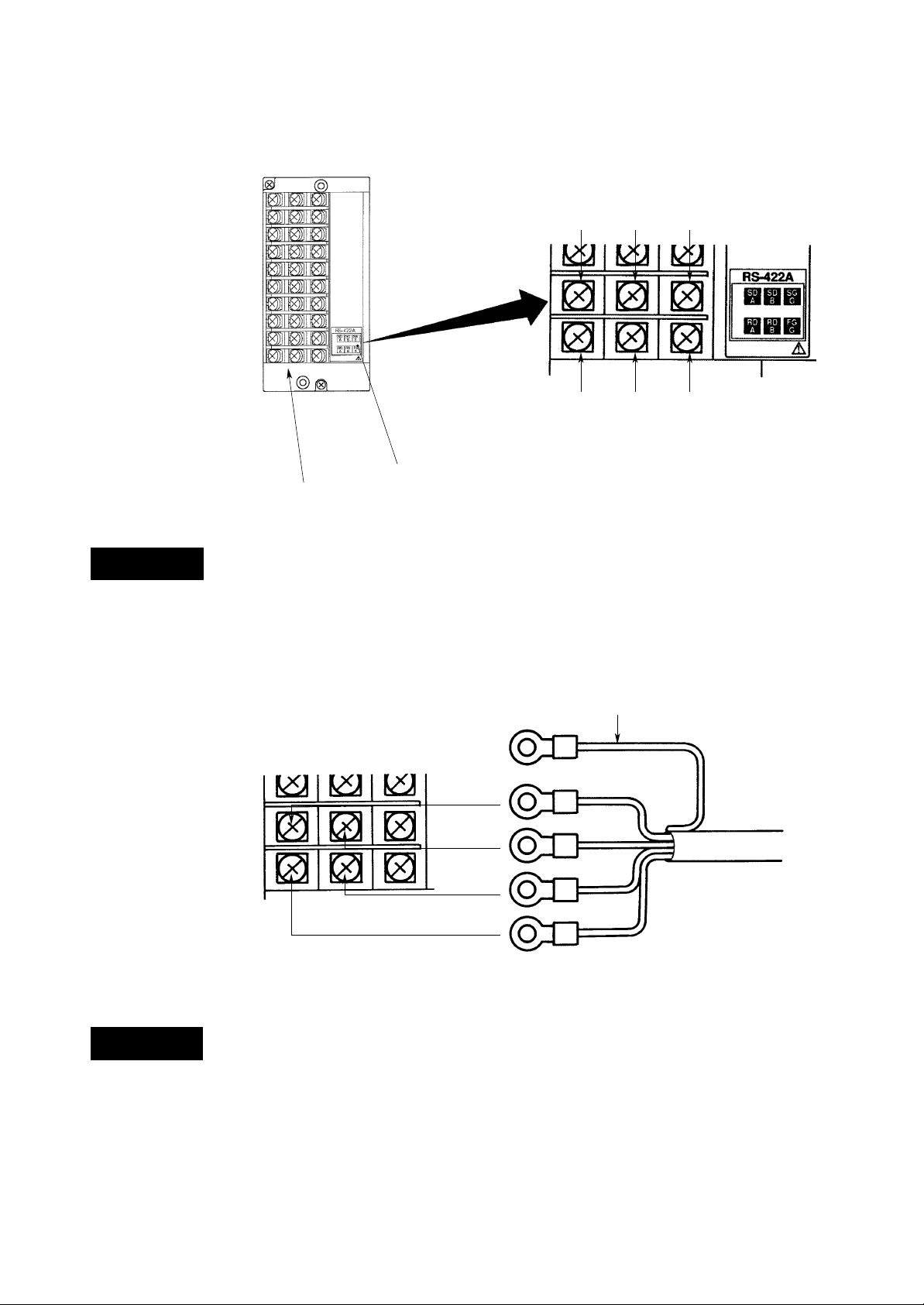
1.2 Interface Terminal
1.2.1 Terminal Arrangement
SD A SD B SG G(Signal Ground)
WARNING
1.2.2 Cable Termination
RD A
Connect RD to TD of computer,
and connect SD to RD of computer.
RS-422-A Indication
Option Terminal Block
Figure 1.1 Terminal Arrangement
RD B FG G(Frame Ground)
There is the power supply terminal near the interface terminal.
To prevent an electric shock, ensure the main power supply is turned OFF.
Shield potential
RS-422-A Terminals
GND
SD A
SD B
WARNING
1 - 2
RD B
RD A
Used terminal screws:
ISO M4, length 6 mm
Figure 1.2 Cable Termination
It is recommended that “crimp on” lugs
(for 4 mm screws) with insulation sleeves
be used for leadwire ends.
There is the power supply terminal near the interface terminal.
To prevent an electric shock, ensure the main power supply is turned OFF.
Page 8
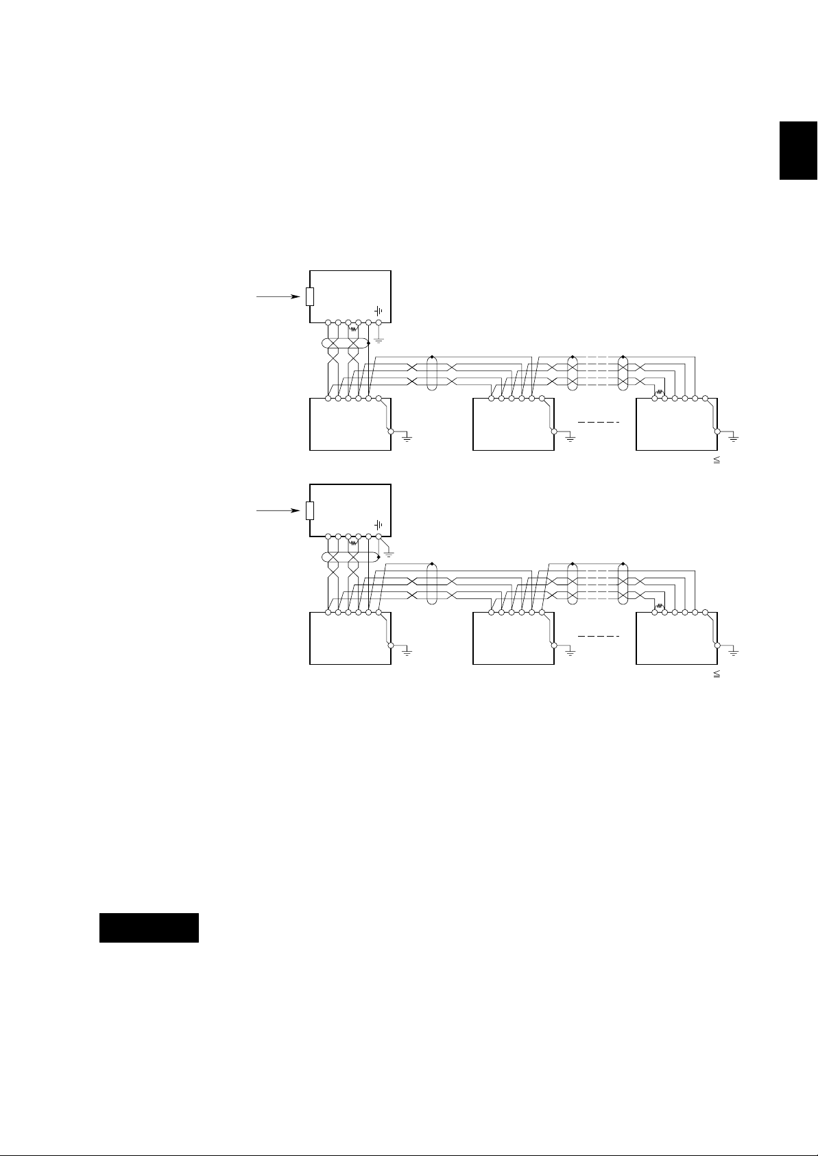
1.3 Communication Wiring
If the host (PC) is equipped with a RS-422-A interface, this recorder can be connected
directly.
If the host (PC) is equipped with a RS-232-C interface, this recorder can be connected
using a converter which has fail safe function (SHARP Z-101HE or equivalent).
Shown below are two wiring examples, which are same except for the case-shielding.
If there will be a connection between other panels, wiring should be done as shown in
figure b.
Personal
Computer
RS-232-C
a
Recorder
TD (–)
*
R
RD A
TD (+)
RD (–)
SD A
RD B
RD (+)
SHIELD
SD B
FG G
SG G
Converter
Z-101HE
(SHARP)
RD A
RD B
SD A
SD B
FG G
SG G
1.3 Communication Wiring
*
R
SD A
SD B
RD A
RD B
FG G
SG G
1 INSTALLATION OF RS-422-A INTERFACE
Personal
Computer
RS-232-C
#1
Converter
Z-101HE
RD (+)
SHIELD
(SHARP)
TD (–)
TD (+)
RD (–)
*
R
#2
b
*
R
Recorder
*: R in figure 1.3 indicates a terminal resistance. R=100 , 1/2W min (adjust according to the impedance).
The converter is of the inverter type. The + and – polarity depends on the type of converter.
Figure 1.3 Communication Wiring
RD A
RD B
#1
SD A
SD B
FG G
SG G
RD A
RD B
#2
SD A
SD B
FG G
SG G
In case of wiring as shown in figure a, use two pairs of 24AWG (minimum) twisted
shielded cables or equivalent.
In case of wiring as shown in figure b, use three pairs of 24AWG (minimum) twisted
shielded cables or equivalent. One pair is used for SG in case of figure b.
(Characteristic impedance: 100 , capacitance 50pF/m)
#n (n 16)
SD A
SD B
RD A
RD B
SG G
#n (n 16)
FG G
WARNING
Keep the terminated unshielded section to a minimum and clear of this recorder ground
line.
There is the power supply terminal near the interface terminal.
To prevent an electric shock, ensure the main power supply is turned OFF.
1 - 3
Page 9

1.4 Data Configuration
The relation between the signal and the potential of the RS-422-A terminals is as
follows: A<B :1
1.4.1 Start-Stop Communication
The RS-422-A interface communicates with the start-stop system. The start-stop system
first adds the start bit to the head and then in turn adds the data bits (7 to 8 bits), parity
bit and stop bit(s) in every transmission of one character (see figure 1.4). See section 1.5
for the address, communication (baud) rate, data length, parity bit, and stop bit(s)
settings.
The start bit is automatically added and no setting is necessary.
Idle status
of the line
1
A>B :0
Data bits (7 to 8 bits)
one character
Restoring the line to the
idle status (broken line)
or start bit of the next
new data (solid line)
1.4.2 Text
0
Start bit
Parity bit: odd,
even or not used
Figure 1.4 Start-Stop System for One Character
Stop bit
1
1 or 2
Communication data usually takes the form of more than one character to which a
terminator is added. This is called ‘text’. See also figure 1.5.
A B C D E CR LF
one character terminator
one text
Figure 1.5 Structure of Text
The RS-422-A interface identifies a text by regarding the reception of a terminator as
the end of text. See also figure 1.6.
identifies text 1 identifies text 2
1 - 4
A B C CR LF D E F G CR LF
text 1 text 2
Figure 1.6 Example of Two Texts, Where the Terminator is CR-LF
NOTE This recorder identifies text by regarding ‘LF’ or ‘;’ as the terminator when receiving
the data (and will send CR and LF as the terminator).
However, only CR + LF is usable as the terminator for open command (ESC O) and
close command (ESC C).
As in the example shown in figure 1.6, when CR and LF are used as the terminator, CR
is ignored. Therefore, when communication is performed with a PC, the terminator LF
might not be sent. Exercise care.
Page 10

1.4.3 Input Buffer
1.4.4 Buffer Overflow
1.4 Data Configuration
The input buffer takes the form of rotary buffer (capacity: 256bytes). The rotary buffer
outputs a text on the first-in first-out basis while storing data in turn. It is not necessary
for the user to be aware of in the program, however take care to prevent buffer overflow. A merit of the rotary buffer is that it can flexibly cope with more than one text
being sent contiguously because of low loss against variable text length.
As described before, the input buffer is necessary for data communication. The capacity, however, is limited (256 bytes for this recorder). Thus, in the receiver,
the buffer capacity may become shorted if vast data is sent in a short time.
These impair data communications (buffer overflow).
To prevent buffer overflow, it is recommended to confirm the status of the recorder
using the ESC S command just after commands have been sent (from the PC). See
subsection 2.4.2.
Note that you cannot send an ESC S command after having sent an LF or FM command.
After the recorder receives the ESC S command, it will output its status to the PC.
Actually, the recorder will store the ESC S command in the input buffer and this
command will be read from this buffer. Then the status will be output to the PC.
If the computer sends other commands before the status of the recorder has been
receiveid, the input buffer will not be empty (the ESC S command will be still in there),
which means the recorder cannot receive other commands yet.
1 INSTALLATION OF RS-422-A INTERFACE
Figure 1.7 Rotary Buffer
start 1
text 1
end 1
start 2
text 2
end 2
text 3 start 3
end 3
1 - 5
Page 11

1.5 How to Set the RS-422-A Interface Communications
1 Remove the recorder packing material as described 1.2.2 in the Instruction Manual of
this recorder and remove the lock screw.
2 Enter the SET UP mode by turning ‘ON’ the power while pressing the [CH UP] (
[ENT] key.
3 Use the [ ] key to select the display ‘ ’. Press the [ENT] key.
4 Set the RS-422-A address (possibilities are from 01 to 16) using the [ ] key.
The initial value is ‘01’. Press the [ENT] key.
5 Select the transmission speed (baud rate). The speed is selcetable from 75, 150, 300,
600, 1200, 2400, 4800 and 9600 bits/second using the [ ] key. After selection, press
the [ENT] key. The initial value is 9600 bps.
6 Select the data length. The length is selectable from (7 bits) or (8
bits) using the [ ] key. After selection, press the [ENT] key. The initial value is 8 bits.
7 Select the parity bit. This bit is selectable from , or using the
[ ] key. After selection, press the [ENT] key. The initial value is .
8 Select the number of stop bits. This is selectable from (1 bits) or (2
bits) usig the [ ] key. After selection, press the [ENT] key. The initial value is 1 bit.
The display ‘ ’ will appear. You can now adjust other settings in the SET UP
mode, by using the [ ] key.
Before leaving the SET UP mode, you have to store your new settings. Press the [ ]
key until the display ‘ ’ appears.
Press the [ENT] key. Select ‘ ’ to keep your new settings or ‘ ’
and press the [ENT] key. After a few seconds, the OPERATION mode will appear.
1 - 6
Page 12

2 RECEIVING FUNCTIONS
This chapter describes program set commands and program control commands. Remember first to open a device by the ESC O command before the set or control commands can be sent.
2.1 Program Set Commands
2.1 Program Set Commands
Commands are represented by ASCII codes and divided into an identifier, parameters,
delimiters and a terminator.
Example: SA02, 1, ON, L, 1000, ON, I04 terminator
parameter
identifier
identifier
• Defined by two alphabetical, capital characters
parameter
• Parameters are separated by a delimiter (comma)
• Numeric data are displayed by integers (e.g. +20, –240)
• When parameters are numeric, the effective setting ranges depend
on these parameters
• Spaces preceding and following a parameter, or a space within a
parameter are ignored.
• Parameters which do not need to be changed can be omitted.
Delimiters, however, can not be omitted. (e.g. SA02, , ON: level
number of alarm is unchanged)
• A string of delimiters at the end of a command/parameter string may be
omitted (see example below).
E.g. SA02, 1, ON, L, , , can be omitted
• The length of the following parameters is fixed. If the length differs,
syntax errors will occur.
- Date and time YY/MM/DD (eight characters)
HH:MM:SS (eight characters)
- Channel CC (two characters, e.g. channel 1 must be entered
as 01)
terminator
A command ends with one of the following terminators:
CR + LF
LF
; (semicolon)
When using the ESC O or ESC C command, only the CR + LF terminator
is valid.
2 RECEIVING FUNCTIONS
2 - 1
Page 13

2.1.1 List of Program Set Commands
Type Command Function
Set SR range setting
NOTE For restrictions concerning settings, see main Instruction Manual.
When setting the above commands, the set mode will appear. When returning to the
OPERATION mode, use the UD command (see subsection 2.2.6).
SM offsets setting
SA alarm setting
SN unit setting
SC chart speed setting
SD clock setting
SS trend recording format setting
(Dot-printing model only)
SZ zone setting
SP partial expanded setting
ST tag setting
SG message setting
SE chart speed 2 setting
SL Key lock setting
2 - 2
Page 14

2.1.2 Range Setting
2.1 Program Set Commands
SKIP
Prevents the specified channel from being measured, recorded and displayed.
format: SRp1, mode designation
example: SR01, SKIP
VOLT, TC, RTD and DELT
format: SRp1, mode designation, p2, p3, p4
p1: channel number (CC)
mode designation: SKIP
2 RECEIVING FUNCTIONS
p1: channel number (CC)
mode designation: VOLT, TC, RTD
DELT (difference computation of measured values between set
channel and reference channel)
p2: range designation
in case of VOLT: 20mV, 60mV, 200mV, 2V, 6V, 20V
in case of TC: R, S, B, K, E, J, T, N, W, L, U
in case of RTD: PT, JPT
in case of DELT: the reference channel number. Note that the
reference channel number must be lower than the set channel.
p3: minimum value of the recording span. Enter within five digits,
regardless of the decimal point and + or –
p4: maximum value of the recording span. Enter within five digits,
regardless of the decimal point and + or –
Input range table
Input type Range Measurement range Unit
DC Voltage 20mV –20.00mV to 20.00mV mV
60mV –60.00mV to 60.00mV mV
200mV –200.0mV to 200.0mV mV
2V –2.000V to 2.000V V
6V –6.000V to 6.000V V
20V –20.00V to 20.00V V
Input type Range Measurement range Measurement range
TC R 0.0 to 1760.0°C 32 to 3200°F
S 0.0 to 1760.0°C 32 to 3200°F
B 0.0 to 1820.0°C 32 to 3308°F
K –200.0 to 1370.0°C –328.0 to 2498.0°F
E –200.0 to 800.0°C –328.0 to 1472.0°F
J –200.0 to 1100.0°C –328.0 to 2012.0°F
T –200.0 to 400.0°C –328.0 to 752.0°F
N 0.0 to 1300.0°C 32 to 2372°F
W 0.0 to 2315.0°C 32 to 4199°F
L –200.0 to 900.0°C –328.0 to 1652.0°F
U –200.0 to 400.0°C –328.0 to 752.0°F
Input type Range Measurement range Measurement range
RTD PT –200.0 to 600.0°C –328.0 to 1112.0°F
JPT –200.0 to 550.0°C –328.0 to 1022.0°F
2 - 3
Page 15

DI (Digital Input)
format: SRp1, mode designation, p2
example: SR01, DI, CONT
SCL (Scaling)
format: SRp1, mode designation, p2, p3, p4, p5, p6, p7
example: SR01, SCL, 20mV, 0, 1000, –1000, 1000, 1
p1: channel number (CC)
mode designation: DI (digital input)
p2: type designation
selectable from LEVL (level) or CONT (contact)
p1: channel number (CC)
mode designation: SCL
p2: mode designation
selectable from VOLT, TC or RTD
p3: range designation
p4: the minimum value of the recording span (SPAN L). Enter 5
digits, regardless of the decimal point and + or –
p5: the maximum value of the recording span (SPAN R). Enter 5
digits, regardless of the decimal point and + or –
p6: the minimum value of the scale (SCL l). Enter 6 digits, regard-
less of the decimal point and + or –
p7: the maximum value of the scale (SCL r). Enter 6
digits, regardless of the decimal point and + or –
p8: decimal point position of scaling value (0 to 4, which stands
for the number of digits after the decimal point)
This example performs 0 to 10mV input in channel 1 and is scaled from –100.0 to
100.0.
NOTE An error will occur if one of p5, p6 or p7 is omitted. However, it is possible to omit all
SQRT (Square Root)
format: SRp1, mode designation, p2, p3, p4, p5, p6, p7
example: SR01, SQRT, 20mV, 0, 1000, –1000, 1000, 1
three values in case you do not want to change them.
p1: channel number (CC)
mode designation: SQRT
p2: range designation
selectable from 20mV, 60mV, 200mV, 2V, 6V, 20V
p3: minimum value of the recording span (SPAN L). Enter within
five digits, regardless of the decimal point and + or –
p4: maximum value of the recording span (SPAN R). Enter within
five digits, regardless of the decimal point and + or –
p5: minimum value of the scale (SCL l). Enter within six digits,
regardless of the decimal point and + or –
p6: maximum value of the scale (SCL r). Enter within six digits,
regardless of the decimal point and + or –
p7: decimal point position of scaling value (0 to 3, which stands for
the number of digits after the decimal point)
This example performs 0 to 10mV input in channel 1. From this value the square root is
taken and the value is scaled from –100.0 to 100.0.
2 - 4
NOTE An error will occur if one of p5, p6 or p7 is omitted. However, it is possible to omit all
three values in case you do not want to change them.
Page 16

2.1.3 Offsets Setting
format: SMp1, p2
2.1.4 Alarm Setting
format: SAp1, p2, ON/OFF, p3, p4, p5, p6
2.1 Program Set Commands
p1: channel number (CC)
p2: offset level (regardless of the decimal point)
p1: channel number (CC)
p2: alarm level number (1 to 4)
ON/OFF: set alarm ON or OFF
p3: the type of alarm, selectable from
H: high limit alarm
L: low limit alarm
h: difference high limit alarm
l: difference low limit alarm
p4: alarm set point. Enter within five digits, regardless of the decimal
point and + or –. See the following table.
Input Type Decimal Point Position
–20.00
to
20.00 mV
–60.00 to 60.00 mV
DC Voltage
–200.0 to 200.0 mV
–2.000 to 2.000 V
–6.000 to 6.000 V
–20.00 to 20.00 V
TC/RTD
p5: activating of the alarm output relay ON/OFF
p6: alarm output relay number. Selectable from I01 to I06, depending on
your option
2 RECEIVING FUNCTIONS
example: SA02, 1, ON, L, 1000, ON, I04
This example sets an level 1, low limit, alarm to channel 2. The alarm set point is
10.00mV and if an alarm occurs, output relay number 4 will be activated.
2.1.5 Unit Setting
format: SNp1, p2
example: SN02, kg
This example assigns the unit ‘kg’ to channel 2. Note that a unit can only be assigned to
channels of the SCL or SQRT input.
2.1.6 Chart Speed Setting
format: SCp1
p1: channel number (CC)
p2: unit characters (up to six)
p1: chart speed (in mm/h)
(10 to 12000 mm/h for the Pen model [40 increments : see the
following table], 10 to 1500mm/h for the Dot-printing model
[28increments]
10
15
20
25
30
40
50
60
90
100
120
150
160
180
200
240
375
450
600
720
750
900
1200
1500
3000
3600
4500
4800
5400
6000
7200
9000
75
300
1800
10800
80
360
2400
12000
example: SC40
This example changes the chart speed to 40 mm/h.
2 - 5
Page 17

2.1.7 Clock Setting
format: SDp1, p2
p1: date (YY/MM/DD)
p2: time (HH:MM:SS)
example: SD97/07/13, 15:02:00
2.1.8 Trend Recording Format Setting
format: SSp1
p1: selection of trend recording mode
NOTE This setting applies only to the Dot-printing model.
2.1.9 Zone Recording Setting
format: SZp1, p2, p3
p1: channel number (CC)
p2: left boundary value (0 to 95)
p3: right boundary value (5 to 100)
selectable from AUTO or FIX
example: SZ02, 30,50
This example results in zone recording for channel 2 in the band from 30 to 50mm.
2.1.10 Partial Expanded Recording Setting
format: SPp1, p2, p3, p4
p1: channel number (CC)
p2: partial expanded recording ON/OFF
p3: percentage of the full recording span which will be compressed.
(1 to 99%)
p4: boundary value (recording span + 1 to recording span – 1)
example: SP01, ON, 25, 0000
This example results in partial expanded recording for channel 1 where the value at
25% of the chart corresponds with 0.000V.
NOTE The decimal point position will be according to the range (or scaling) setting. See also
the input range table on page 2-3.
2.1.11 Tag Setting
format: STp1, p2
p1: channel number (CC)
p2: tag characters (up to seven characters)
2 - 6
example: ST01, TAG 1
Page 18

2.1.12 Message Setting
format: SGp1, p2
example: SGMSG2, TEST1
2.1 Program Set Commands
p1: message number (selectable from MSG1, MSG2, MSG3, MSG4,
MSG5)
p2: message characters (up to 16 characters)
This example sets the message ‘TEST1’ as message number 2.
2.1.13 Chart Speed 2 Setting
format: SEp1
example: SE100
This example sets the second chart speed to 100 mm/h.
2.1.14 Key Lock Setting
format: SLp1, p2, p3
2 RECEIVING FUNCTIONS
p1: second chart speed (in mm/h)
(10 to 12000 mm/h for the Pen model [40 increments],
10 to 1500 mm/h for the Dot-printing model [28 increments])
p1: RCD key
LOCK
FREE
p2: PRINT key
LOCK
FREE
p3: FEED key
LOCK
FREE
example: SL LOCK, FREE, LOCK
This example releases the Key Lock of the [PRINT] key.
2 - 7
Page 19

2.2 Program Control Commands
2.2.1 List of Program Control Commands
Type Command Function
Control PS start/stop recording
MP manual printout start/stop
LS list printout start/stop
SU SET UP list printout start/stop
MS message printout start
UD returning display OPERATION mode
BO designation sequence of byte output (Binary output)
TS selection of output data
FM selection of output format of measured data
LF selection of output format for unit/decimal point
2.2.2 Start/Stop the Recording
Command Function
PS0 starts the recording
PS1 stops the recording
2.2.3 Manual Printout Start/Stop
Command Function
MP0 starts the manual printout
MP1 stops the manual printout
2.2.4 List Printout Start/Stop
Command Function
LS0 starts the list printout
LS1 stops the list printout
2.2.5 Message Printout Start
Command Function
MSp1 starts the message printout
Where p1 is the message number
selectable from 1 (MSG1), 2 (MSG2), 3 (MSG3), 4 (MSG4), 5 (MSG5)
2 - 8
Page 20

2.2.6 Returning Display to OPERATION Mode
Command Function
UD0 selects AUTO display
UD1, p1 selects MANUAL display
UD2 selects DATE display
UD3 selects CLOCK display
UD4 selects OFF
Where p1 is the channel number (CC)
2.2.7 Designation Sequence of Byte Output (Binary output)
Command Function
BO0 outputs from MSB (upper byte)
BO1 outputs from LSB (lower byte)
2.2.8 Selection of Output Data
Command Function
TS0 outputs measured values
TS1 outputs values of setting parameters
TS2 outputs unit and decimal point information
2.2 Program Control Commands
2 RECEIVING FUNCTIONS
2.2.9 Selection of Output Format for Measured Data
Command Function
FM0, p1, p2 selects channels from which measured values are output in ASCII mode
FM1, p1, p2 selects channels from which measured values are output in Binary mode
where p1 is the channel number (CC) from where the output should start, and p2 is the
channel number (CC) where the output should end
NOTE After you designated the output to be measured values (TS0 command), specify the
format by this FM command.
2.2.10 Selection of Output Format for Unit/Decimal Point Information
Command Function
LF, p1, p2 selects channels from which unit/decimal point information is output
(TS2)
where p1 is the channel number (CC) from where the output should start, and p2 is the
channel number (CC) where the output should end
NOTE After you designated the output by a TS2 command, specify the format by this LF
command.
2 - 9
Page 21

2.3 Escape Sequence
Communications can be controlled by using the following escape commands.
2.3.1 Execution of Trigger
ESC T executes triggering
If an ESC T command is received,
• measured data (when TS0 is specified), or
• units & decimal point information (when TS2 is specified)
are stored in a buffer.
Data output will start only after the output format has been designated (using the FM or
LF command).
For actual use and output sequence, see section 3.2, ‘‘output data format’’.
ESC T sends a character ‘T’ following data of 1 byte (1B) H.
2.3.2 Status Output
ESC S outputs status
Example: If (ESC T) is output using PC 9801 Series:
PRINT #1,CHR$ (&1HB) +’T’;
(In case of NEC PC 9801, the interface file number should be
1 and should be opened.)
If the ESC S command is received, statuses of the commands which have been sent so
far are output.
Output statuses range from ER00 to ER07. For the respective contents, see the next
figure and table.
7 6 5 4 3 2 1 0
A/D conversion ends (only
for Dot-printing model, Pen
model is always 0)
Syntax error occurs
Periodic printing time up
0
0
0
0
Figure 2.1 Output Format after ESC S Command Has Been Sent
0
NOTE Status will be reset (0) after the error message has been output.
Example:
2 - 10
A/D conversion ends
ESC S
Status of error 1
'A/D conversion ends' 0
Page 22

2.3 Escape Sequence
Table 2.1 Status Output Table
Status
Status
Output
A/D END Syntax
Error
periodic
printing
time up
ER00C L
R F
ER01C L
R F
ER02C L
R F
ER03C L
R F
ER04C L
R F
ER05C L
R F
ER06C L
R F
ER07C L
R F
: Status
If an error message is output, all error statuses will be reset. This error will not be reset.
If there are no statuses to be output when the ESC S command is received, ER00 will be
output.
Data from the recorder is output using an FM or LF command. To allow time to output
these data, do not send an ESC S command immediately after sending the FM or LF
command.
ESC S sends a character ‘S’ following data of 1 byte (1B) H.
Example: If (ESC S) is output using PC 9801 Series:
PRINT #1,CHR$ (&1HB) +’S’;
LINE INPUT #1, D$
PRINT D$
(In case of NEC PC 9801, the interface file number should be
1 and should be opened.)
2 RECEIVING FUNCTIONS
2.3.3 Open Command
2.3.4 Close Command
(ESC O)_ CRL
F
where is the address (ASCII code ‘01’ to ‘16’)
The open command is to address a communication destination when a HOST (PC) is
connected to more than one (up to 16) recorders.
This command always controls non-addressed devices.
Before issuing an open command, make sure that the previous address device is closed
by a close command.
All commands (incl. ESC T) are valid for the addressed (after ESC O) device only.
Only CR + LR can be used as the terminator.
(ESC C)_ CRL
F
where is the address (ASCII code ‘01’ to ‘16’)
The close command is to close the addressed state of a device. Only the addressed
device will respond to this command.
Only CR + LR can be used as the terminator.
2 - 11
Page 23

3.1 Introduction to Output Data Formats
3 TRANSMITTING FUNCTIONS
This chapter describes different output formats.
3.1 Introduction to Output Data Formats
The format to output data can be specified by the following commands (see subsection
2.2.9):
• TS0
• TS1, TS2
NOTE When you specify a TS command and send an ESC T command, the TS command will
be reset. However, if you send an ESC T command again, the TS command will be set
to the previous value.
3.1.1 TS0
After sending the TS0 and the ESC T command, you must specify the output format
using an FM command. Data cannot be output when an FM command is omitted.
However, after the FM command has been sent, data within the same sample can be
output again by specifying the output format once more using an FM command. If the
next FM command is sent before the specified data have been output completely, the
newly requested data will be output.
3 TRANSMITTING FUNCTIONS
3.1.2 TS1, TS2
Sequence (see also subsection 2.2.9, 2.2.10)
TS0
ESC T
FMx, xx, xx
(read data completely)
FMx, xx, xx
(read data completely)
NOTE Do not send any FM or LF commands until the data have been sent completely.
After sending an ESC T command, data will be stored in a buffer and the system will
wait for FM or LF commands. (Regardless whether the ESC T command is sent without
executing FM or LF command, or whether data have been sent completely.)
The ASCII code for ESC is (1B)H.
After sending the TS1 (or TS2) and the ESC T command, you must specify the output
channel using an LF command. It is possible, after data have been output completely, to
output data from another channel by specifying an LF command again.
Sequence (see also subsection 2.2.9, 2.2.10)
TS2
ESC T
LFxx, xx
(read data (end data))
LFxx, xx
(read data (end data))
NOTE Do not send any FM or LF commands until the data have been sent completely.
After sending an ESC T command, data will be stored in a buffer and the system will
wait for FM or LF commands.
3 - 1
Page 24

3.2 Output Data Formats
There are four formats which can be used to output data.
• TS0 + ESC T + FM0 (outputs measured values in ASCII mode)
• TS0 + ESC T + FM1 (outputs measured values in Binary mode)
• TS1 + ESC T + LF (outputs values of setting parameters)
• TS2 + ESC T + LF (outputs information on unit and decimal point)
3.2.1 Output Format of Measured Values in the ASCII Mode
When the TS0, ESC T and FM0 commands are received, the measured value and
computed result are output in ASCII mode. When the ESC T command is received
immediately after the TS0 command, the recorder data will be transferred to a buffer.
Output format:
DATEYYMMDDC
TIMEHHMMSSC
(year, month, day)
RLF
(hour, minute, second)
RLF
AAAAUUUUUUCC, ±DDDDDE±EEC
1 2 3 4 1 2 3 4 5 6
Data exponent
E±2 digits
Data mantissa
±5 digits
Channel number
01 to 06
Units
mV mV
VV
C °C
U U U U U U Arbitrary
1 2 3 4 5 6
Alarm status (place corresponds to level)
H : High alarm
L : Low alarm
h : Difference high limit alarm
l : Difference low limit alarm
: No alarm
Data status
space : middle and other data
E : end of data
Data status
N : normal
D : differential data (DELT)
O : overrange (data ± 99999)
S : skip
RLF
3 - 2
Page 25

3.2.2 Output Format of Measured Values in the Binary Mode
When the TS0, ESC T and FM1 commands are received, the measured value and
computed result are output in the Binary mode.
Output format
Transfer order
output byte number 2 byte
date and time 6 byte
measured data (1) 5 byte
|
measured data (n) 5byte
Output byte number
output byte number= 5 x n+6 (order of output byte can be selected)
The output byte number is output from the most significant byte (MSB) or least
significant byte (LSB) according to the output sequence (BO command). Note
that in the mentioned formula the above mentioned 2 bytes are not included.
Date and time
Year, Month, Day, Hour, Minute, Second
3.2 Output Data Formats
3 TRANSMITTING FUNCTIONS
Year: 0 to 99 (00H to 63H)*
Month: 1 to 12 (01H to 0CH)*
Day: 1 to 31 (01H to 1FH)*
Hour: 0 to 23 (00H to 17H)*
Minute: 0 to 59 (00H to 3BH)*
Second: 0 to 59 (00H to 3BH)*
* Output is hexadecimal, therefore numeric output needs to be converted.
1 2 3 4 5
A2 A1 A4 A3
Channel
number
(1 to 24)
Alarm status
An=1: H
An=2: L
An=3: h
An=4: l
An=0: No alarm or set to OFF
Outputs for each level:
A1 = level 1
|
A4 = level 4
Measured value (order of output byte
can be selected, using BO command)
data + over: 7E7E is output
data – over: 8181 is output
skip: 8080 is output
3 - 3
Page 26

Measured data:
3.2.3 Output Format of Setting Parameters
When the TS1, ESC T and LF commands are received, setting parameters are output in
the following order (the set values are output in the same format as input):
Communication Set value output
PS start/stop recording
SR range setting
SM offsets setting
SN unit setting
SA alarm setting
SC chart speed setting
SS trend recording format setting
SZ zone setting
SP partial expanded setting
ST tag setting
SG message setting
SE chart speed 2 setting
SL key lock setting
UD selection of display
EN the end of setting parameter output
3.2.4 Output Format of Information on Unit and Decimal Point
When the TS2, ESC T and LF commands are received, information on units and
decimal points are output in the following format. Channel numbers can be specified
with the LF command.
CC UUUUUU
1 2 1 2 3 4 5 6
, CRL
F
Position of decimal point.
This number indicates the number of
digits after the decimal point (0 to 4)
U: unit (six characters)
C: channel number (two characters)
Data status
: middle and other data
E: final data
Data status
N: normal
D: differential
S: skip
3 - 4
Page 27

3.3 Status Byte Format
When an ESC S command is received, status is output in the following format:
ER
CRL
Status
Output
ER00C L
R F
ER01C L
R F
ER02C L
R F
ER03C L
R F
ER04C L
R F
ER05C L
R F
ER06C L
R F
ER07C L
R F
F
A/D END Syntax
Status
Error
3.3 Status Byte Format
periodic
printing
time up
3 TRANSMITTING FUNCTIONS
: Status
3 - 5
Page 28

4 TIME CHART
6
6
6
6
6
6
2
2
2
2
2
2
one sample
A/D and
primary computation
ESC T command
Output of data
The sample period is 125ms for the Pen model and 5s for the Dot-printing model.
When the ESC T command is received to output data before data is updated, the
previous sample data will be output.
234567890123456789012345
234567890123456789012345
234567890123456789012345
234567890123456789012345
234567890123456789012345
234567890123456789012345
234567890123456789012345678901212345678901
234567890123456789012345678901212345678901
234567890123456789012345678901212345678901
234567890123456789012345678901212345678901
234567890123456789012345678901212345678901
234567890123456789012345678901212345678901
4 TIME CHART
4 - 1
Page 29

5 INITIAL STATUS
The initial status after turning the power ON is shown below.
TS0 output format is designated to be measured values
FM0, 01, 06* output format is designated to be measured values in ASCII mode
output start channel: 01
output end channel: 06
LF 01, 06* units and decimal point position to be output
start channel: 01
end channel: 06
BO0 From most significant byte (MSB)
* Depending on the recorder model, the highest channel number will be the initial
status.
NOTE The contents of RS-422-A cannot be backed up by a battery.
5 INITIAL STATUS
5 - 1
Page 30

ASCII Code Table
First digit
1
0
0
23456789ABCDEF
S
P
/
0
P
p
1
2
3
4
5
Second digit
6
7
8
9
L
A
F
B
C
C
D
R
E
F
q
W
a
Q
r
b
R
s
c
S
t
d
T
u
e
U
v
f
V
w
g
x
h
X
y
i
Y
z
j
Z
k
l
m
n
o
1
A
2
B
3
#
%
(
)
/
ESC
*
+
C
4
D
5
E
6
F
7
G
8
H
9
I
J
:
K
L
/
–
.
/
M
N
O
˚
µ
5 - 2
NOTE The degree symbol (°) of °C should be selected as follows:
• In case of Measured values output (TS0) and Unit, Decimal point output (TS2):
° = space (20H)
• In case of setting parameter output (TS1):
° = E1H
• In case of recorder setting:
° = E1H
Page 31

6.1 Preventing Errors
6 ERRORS DURING RS-422-A OUTPUT
6.1 Preventing Errors
Do not send an FM or LF command until the measured data or set point data in the
specified channel is output. If an FM or LF command is sent during data output, the
communication will be interrupted.
If an LF command (to set TS0) or an FM command (to set TS1 or TS2) is sent, the
communication will be interrupted.
If an ESC T command was already sent when TS0 is set, data (even in other formats) in
any channel can be output with an FM command. Data received with the last ESC T is
output.
If an ESC T command was already sent when TS1 or TS2 is set, data set in any channel
can be output with an LF command. If an ESC T command was already sent, the
measured data and set point data can be output on a channel-by-channel.
If an ESC T command has already been sent, the measured value and set value can be
output over more than one time.
NOTE When data is sent from the PC to the recorder, use the ESC S command to avoid buffer
overflow:
This recorder receives an ESC S request, and saves it in the buffer memory. This
request is retrieved from the buffer memory and, after command acknowledgement, the
status is sent to the PC. Make sure not to send any other commands between sending the
ESC S command to the recorder and reading the status from the recorder. Commands
can be only received by the recorder when its input buffer is empty.
6 ERRORS DURING RS-422-A OUTPUT
Example (Dot-printing model):
10 OPEN "COM1:N81N" AS #1
20 '
30 PRINT #1,CHR$(&H1B)+"O 01"
40 PRINT #1,"SA02,1,ON,L,1000,ON,I04"
5 0 GOSUB *HANDSHAKE
60 PRINT #1,"PS0"
7 0 GOSUB *HANDSHAKE
80 PRINT #1,"UD0"
90 PRINT #1,CHR$(&H1B)+"C 01"
1 0 0 CLOSE
110 END
120 *HANDSHAKE
130 PRINT #1,CHR$(&H1B)+"S"; (sending ESC S)
140 LINE INPUT #1,STS$ (reading status)
1 5 0 RETURN
to prevent buffer overflow
Command length of input buffer of this recorder is 256 bytes.
NOTE When the PC9801 receives binary data from the recorder, set the memory switches so
that the PC9801 can use a DEL mode as a BS(08) code. For memory setting, see the
PC9801 Instruction Manual.
6 - 1
Page 32

NOTE Binary data cannot use a LINE INPUT statement. To read binary data, use an INPUT$
statement.
Example (Dot-printing model):
10 OPEN "COM1:N81N" AS #1
20 '
30 PRINT #1,CHR$(&H1B)+"O 01"
40 PRINT #1,"BO1"
50 PRINT #1,"TS0"
60 PRINT #1,CHR$(&H1B)+"T";
70 PRINT #1,"FM1,01,04"
80 D$=INPUT$(2,#1) (to designate data length of read data)
90 CNT=CVI(D$)
100 D$=INPUT$(CNT,#1)
1 1 0 CLOSE
120 END
Execution of the above program may result in the following:
After line 100 has been executed, binary data will be stored in D$.
It the output data length "CNT" in line 90 exceeds 255, the read-data is separated into
several parts.
When binary data is handled in an integer array on a 2-byte basis, the least significant
byte is followed by the most significant byte, so an FM command should specify an
output byts from the LSB (least significant byte) (line 40).
6.2 How to Request for Error Message Output
If an error occurs when a supervisory computer sends a setting or control command to
the recorder via the RS-422-A communication interface, an error message can be output
from the recorder upon receipt of a command from the computer.
1 request to output error message number
command: ESC S
(1B) H (53) H
2 error message output from the recorder when ESC S is received.
Output format: ERxx (CR) (LF) (xx = 00 to 07. Refer to 3.3 for details)
NOTE An error message is only output when an ESC S command is sent.
If an ESC S command (request to send error message) is sent to the recorder while data
is being output due to the receipt of a TS0 or TS2 command, communication will be
interrupted.
When data is transmitted between a supervisory computer and the recorder, it is possible
to monitor the errors during communication through the ESC S command.
6.3 Timing of Resetting Error Status
When the recorder receives an ESC S command following the occurrence of an error,
the recorder outputs the corresponding error message and the error status is simultaneously reset.
error occurs ESC S command is sent
6 - 2
• outputs error message
• resets the error
Figure 6.1 Timing
Page 33

7.1 Sample Programs for NEC PC 9801
7 SAMPLE PROGRAMS
7.1 Sample Programs for NEC PC 9801
Used computer: NEC PC 9801
Mode: 8 bit, NONE parity, stop bit 1, baud rate 9600 bps
Handshake: NONE
The file name used for writing to and reading from the disc is TEST.DAT.
7.1.1
Program to Read Information on Unit and Decimal Point from the recorder, Display on Screen and
Write to Disc (Dot-printing model)
10 OPEN “COM1:N81N” AS #1
20 OPEN “TEST.DAT” FOR OUTPUT AS #2
30 ‘
40 PRINT #1,CHR$(&H1B)+”O 01"
50 PRINT #1,” TS2"
60 PRINT #1,CHR$(&H1B)+”T”;
70 PRINT #1,” LF01,04"
80 LINE INPUT #1,D$
90 PRINT D$
100 PRINT #2,D$
110 IF MID$(D$,2,1)<>”E ” THEN GOTO 80
120 ‘
130 PRINT #1,CHR$(&H1B)+”C 01"
1 4 0 CLOSE
150 END
7.1.2 Program to Output Measured Data (ASCII code) from the recorder and Write to Disc (
printing model
)
10 OPEN “COM1:N81N” AS #1
20 OPEN “TEST.DAT” FOR OUTPUT AS #2
30 ‘
40 PRINT #1,CHR$(&H1B)+”O 01"
50 PRINT #1,” TS0"
60 PRINT #1,CHR$(&H1B)+”T”;
70 PRINT #1,” FM0,01,04"
80 LINE INPUT #1,D$
90 PRINT D$
100 PRINT #2,D$
110 IF MID$(D$,2,1)<>”E ” THEN GOTO 80
120 ‘
130 PRINT #1,CHR$(&H1B)+”C 01"
1 4 0 CLOSE
150 END
Dot-
7 SAMPLE PROGRAMS
7 - 1
Page 34

7.1.3 Program to Output Measured Data (Binary code) from the recorder and Write to Disc (
)
model
10 OPEN “COM1:N81N” AS #1
20 OPEN “TEST.DAT” FOR OUTPUT AS #2
30 ‘
40 PRINT #1,CHR$(&H1B)+”O 01"
50 PRINT #1,”TS0"
60 PRINT #1,”BO1"
70 ‘
80 PRINT #1,CHR$(&H1B)+”T”;
90 PRINT #1,” FM1,01,04"
100 D$=INPUT$(2,#1)
110 PRINT #2,D$
120 A=CVI(MID$(D$,1,2))
130 PRINT A
140 D$=INPUT$(A,#1)
150 PRINT #2,D$
160 PRINT ASC(MID$(D$,1,1)); :PRINT “ /”;
170 PRINT ASC(MID$(D$,2,1)); :PRINT “ /”;
180 PRINT ASC(MID$(D$,3,1)); :PRINT
190 PRINT ASC(MID$(D$,4,1)); :PRINT “ : ”;
200 PRINT ASC(MID$(D$,5,1)); :PRINT “ : ”;
210 PRINT ASC(MID$(D$,6,1))
220 ‘
230 L=0
240 FOR I=7 TO A
250 PRINT RIGHT$(“ 0” +HEX$(ASC(MID$(D$,I,1))),2)+”“;
260 L=L+1
270 IF L=5 THEN L=0 : PRINT
280 NEXT I
290 ‘
300 PRINT #1,CHR$(&H1B)+”C 01"
3 1 0 CLOSE
320 END
Dot-printing
7 - 2
Page 35

7.2 Sample Programs for YEWMAC
7.2 Sample Programs for YEWMAC
Used computer: YEWMAC with RS 3 card installed (serial interface card) to line
controller slot 3 and using port 1
Mode: 8 bit, NONE parity, stop bit 1, baud rate 9600 bps
Handshake: NONE
7.2.1 Program to Read Information on Unit and Decimal Point from the recorder and Display on
Screen (
Dot-printing model
10 ASSIGN RS3=3
20 RESET 3
30 CONTROL 3,105;1 :! DATA LENGTH 8 bit
40 CONTROL 3,106;0 :! STOP BIT 1
50 CONTROL 3,107;0 :! PARITY NONE
60 CONTROL 3,108;13 :! 9600 BAUD
70 !
80 DIM D$128
90 OUTPUT 3,1;CHR$(27)+”O 01"
100 OUTPUT 3,1;”TS2"
110 OUTPUT 3,1;CHR$(27)+”T ”;
120 OUTPUT 3,1;”LF01,04"
130 ENTER 3,1;D$
140 PRINT D$
150 IF MID$(D$,2,1)<>”E ” THEN GOTO 130
160 OUTPUT 3,1;CHR$(27)+”C 01"
170 END
)
7.2.2 Program to Output Measured Data (ASCII code) from the recorder and Display on Screen
Dot-printing model
(
)
10 ASSIGN RS3=3
20 RESET 3
30 CONTROL 3,105;1 :! DATA LENGTH 8 bit
40 CONTROL 3,106;0 :! STOP BIT 1
50 CONTROL 3,107;0 :! PARITY NONE
60 CONTROL 3,108;13 :! 9600 BAUD
70 !
80 DIM D$128
90 OUTPUT 3,1;CHR$(27)+”O 01"
100 OUTPUT 3,1;”TS0"
110 OUTPUT 3,1;CHR$(27)+”T ”;
120 OUTPUT 3,1;”FM0,01,04"
130 ENTER 3,1;D$
140 PRINT D$
150 IF MID$(D$,2,1)<>”E ” THEN GOTO 130
160 OUTPUT 3,1;CHR$(27)+”C 01"
170 END
7 SAMPLE PROGRAMS
7 - 3
Page 36

7.2.3 Program to Output Measured Data (Binary code) from the recorder and Display on Screen
Dot-printing model
(
)
10 ASSIGN RS3=3
20 RESET 3
30 CONTROL 3,105;1 :! DATA LENGTH 8 bit
40 CONTROL 3,106;0 :! STOP BIT 1
50 CONTROL 3,107;0 :! PARITY NONE
60 CONTROL 3,108;13 :! 9600 BAUD
70 CONTROL 3,118;0 :! NO TERMINATOR
80 CONTROL 3,119;1 :! RECEIVE 1 BYTE
90 !
100 DIM D$1(128)
110 CR$=CHR$(13)
120 LF$=CHR$(10)
130 !
140 OUTPUT 3,1;CHR$(27)+”O 01"+CR$+LF$
150 OUTPUT 3,1;”TS0"+CR$+LF$
160 OUTPUT 3,1;”BO1"+CR$+LF$
170 OUTPUT 3,1;CHR$(27)+” T ”
180 OUTPUT 3,1;”FM1,01,04"+CR$+LF$
190 !
200 ENTER 3,1 NOFORMAT ; D$(*) :! DATA BYTE QTY
210 A=ASC(D$(0))
220 ENTER 3,1 NOFORMAT ; D$(*)
230 A=A + ASC(D$(0))*256
240 PRINT A
250 !
260 ENTER 3,1 NOFORMAT ; D$(*) :! YEAR
270 PRINT ASC(D$(0)); :PRINT “/”;
280 ENTER 3,1 NOFORMAT ; D$(*) :! MONTH
290 PRINT ASC(D$(0)); :PRINT “/”;
300 ENTER 3,1 NOFORMAT ; D$(*) :! DAY
310 PRINT ASC(D$(0)); :PRINT
320 ENTER 3,1 NOFORMAT ; D$(*) :! HOUR
330 PRINT ASC(D$(0)); :PRINT “:”;
340 ENTER 3,1 NOFORMAT ; D$(*) :! MINUTE
350 PRINT ASC(D$(0)); :PRINT “:”;
360 ENTER 3,1 NOFORMAT ; D$(*) :! SECOND
370 PRINT ASC(D$(0))
380 !
390 L=0
400 FOR I=7 TO A
410 ENTER 3,1 NOFORMAT ; D$(*)
420 PRINT RIGHT$(“ 0”+HEX$(ASC(D$(0))),2); : PRINT ““;
430 L=L+1
440 IF L=5 THEN L=0 : PRINT : ENDIF
450 NEXT I
460 !
470 OUTPUT 3,1;CHR$(27)+”C 01"
480 END
7 - 4
Page 37

7.3 Sample Programs for IBM PC
7.3 Sample Programs for IBM PC
Used computer: IBM PC
Mode: 8 bit, NONE parity, stop bit 1, baud rate 1200 bps
Handshake: NONE
The file name used for writing to and reading from the disc is TEST.DAT.
7.3.1
Program to Read Information on Unit and Decimal Point from the recorder, Display on Screen and Write
to Disc (
Dot-printing model
)
10 OPEN “COM1:1200,N,8,1,LF” AS #1
20 OPEN “TEST.DAT” FOR OUTPUT AS #2
30 ‘
40 LF$=CHR$(&HA) :’ Line feed = 0AH
50 PRINT #1,CHR$(27)+” O 01"
60 PRINT #1,” TS2"
70 PRINT #1,CHR$(27)+” T”;
80 PRINT #1,” LF01,04"
90 LINE INPUT #1,D$
100 IF LEFT$(D$,1)=LF$ THEN D$=MID$(D$,2) :’ Remove “LF” of head string
110 PRINT D$
120 PRINT #2,D$
130 IF MID$(D$,2,1)<>”E ” THEN GOTO 90
140 ‘
150 PRINT #1,CHR$(27)+”C 01"
1 6 0 CLOSE
170 END
7.3.2 Program to Output Measured Data (ASCII code) from the recorder and Write to Disc (
printing model
)
10 OPEN “COM1:1200,N,8,1,LF” AS #1
20 OPEN “TEST.DAT” FOR OUTPUT AS #2
30 ‘
40 LF$=CHR$(&HA) :’ Line feed = 0AH
50 PRINT #1,CHR$(27)+” O 01"
60 PRINT #1,” TS0"
70 PRINT #1,CHR$(27)+” T”;
80 PRINT #1,” FM0,01,04"
90 LINE INPUT #1,D$
100 IF LEFT$(D$,1)=LF$ THEN D$=MID$(D$,2) :’ Remove “LF” of head string
110 PRINT D$
120 PRINT #2,D$
130 IF MID$(D$,2,1)<>”E ” THEN GOTO 90
140 ‘
150 PRINT #1,CHR$(27)+”C 01"
1 6 0 CLOSE
170 END
Dot-
7 SAMPLE PROGRAMS
7 - 5
Page 38

7.3.3 Program to Output Measured Data (Binary code) from the recorder and Write to Disc (
printing mode
l)
10 OPEN “COM1:1200,N,8,1,LF” AS #1
20 OPEN “TEST.DAT” FOR OUTPUT AS #2
30 ‘
40 PRINT #1,CHR$(27)+”O 01"
50 PRINT #1,”TS0"
60 PRINT #1,”BO1"
70 ‘
80 PRINT #1,CHR$(27)+” T” ;
90 PRINT #1,” FM1,01,04"
100 D$=INPUT$(2,#1)
110 PRINT #2,D$
120 A=CVI(MID$(D$,1,2))
130 PRINT A
140 D$=INPUT$(A,#1)
150 PRINT #2,D$
160 PRINT ASC(MID$(D$,1,1));:PRINT “ /”;
170 PRINT ASC(MID$(D$,2,1));:PRINT “ /”;
180 PRINT ASC(MID$(D$,3,1));:PRINT
190 PRINT ASC(MID$(D$,4,1));:PRINT “ :” ;
200 PRINT ASC(MID$(D$,5,1));:PRINT “ :” ;
210 PRINT ASC(MID$(D$,6,1))
220 ‘
230 L=0
240 FOR I=7 TO A
250 PRINT RIGHT$(“ 0” +HEX$(ASC(MID$(D$,I,1))),2)+”“;
260 L=L+1
270 IF L=5 THEN L=0 : PRINT
280 NEXT I
290 ‘
300 PRINT #1,CHR$(27)+”C 01"
3 1 0 CLOSE
320 END
Dot-
7 - 6
Page 39

WARRANT Y/DISCLAIMER
OMEGA ENGINEERING, INC. warrants this unit to be free of defects in materials and workmanship for a
period of 25 months f rom date of purchase. OMEGA Warranty adds an additional one (1) month grace
period to the normal two (2) year product war r a n t y to cover handling and shipping time. This
ensures that OMEGA’s customers receive maximum coverage on each product.
If the unit malfunctions, it must be re t u rned to the factory for evaluation. OMEGA’s Customer Serv i c e
D e p a rtment will issue an Authorized Return (AR) number immediately upon phone or written re q u e s t .
Upon examination by OMEGA, if the unit is found to be defective, it will be re p a i red or replaced at no
c h a rge. OMEGA’s WARRANTY does not apply to defects resulting from any action of the purc h a s e r, including but not limited to mishandling, improper interfacing, operation outside of design limits,
i m p roper re p a i r, or unauthorized modification. This WARRANTY is VOID if the unit shows evidence of
having been tampered with or shows evidence of having been damaged as a result of excessive corro s i o n ;
or current, heat, moisture or vibration; improper specification; misapplication; misuse or other operating
conditions outside of OMEGA’s c o n t rol. Components which wear are not warranted, including but not
limited to contact points, fuses, and triacs.
OMEGA is pleased to offer suggestions on the use of its various products. However,
OMEGA neither assumes responsibility for any omissions or errors nor assumes liability for any
damages that result from the use of its products in accordance with information provided by
OMEGA, either verbal or written. OMEGA warrants only that the parts manufactured by it will be
as specified and free of defects. OMEGA MAKES NO OTHER WARRANTIES OR
R E P R E S E N T ATIONS OF ANY KIND WHATSOEVER, EXPRESS OR IMPLIED, EXCEPT THAT OF TITLE,
AND ALL IMPLIED WARRANTIES INCLUDING ANY WARRANTY OF MERCHANTABILITY AND FITNESS FOR A P A R TICULAR PURPOSE ARE HEREBY DISCLAIMED. LIMITATION OF
L I A B I L I T Y : The remedies of purchaser set forth herein are exclusive, and the total liability of
OMEGA with respect to this or d e r, whether based on contract, war r a n t y , negligence,
indemnification, strict liability or otherwise, shall not exceed the purchase price of the
component upon which liability is based. In no event shall OMEGA be liable for
consequential, incidental or special damages.
CONDITIONS: Equipment sold by OMEGA is not intended to be used, nor shall it be used: (1) as a “Basic
Component” under 10 CFR 21 (NRC), used in or with any nuclear installation or activity; or (2) in medical
applications or used on humans. Should any Product(s) be used in or with any nuclear installation or
a c t i v i t y, medical application, used on humans, or misused in any way, OMEGA assumes no re s p o n s i b i l i t y
as set forth in our basic WA R R A N TY/DISCLAIMER language, and, additionally, purchaser will indemnify
OMEGA and hold OMEGA h a rmless from any liability or damage whatsoever arising out of the use of the
P roduct(s) in such a manner.
RETURN REQUEST S / INQUIRIES
Direct all warranty and repair requests/inquiries to the OMEGA Customer Service Department. BEFORE
RETURNING ANY PRODUCT(S) TO OMEGA, PURCHASER MUST OBTAIN AN AUTHORIZED RETURN
(AR) NUMBER FROM OMEGA’S CUSTOMER SERVICE DEPA RTMENT (IN ORDER TO AV O I D
PROCESSING DELAYS). The assigned AR number should then be marked on the outside of the return
package and on any correspondence.
The purchaser is responsible for shipping charges, freight, insurance and proper packaging to prevent
breakage in transit.
FOR WARRANTY RETURNS, please have the
following information available BEFORE
contacting OMEGA:
1 . P u rchase Order number under which the pro d-
uct was PURCHASED,
2. Model and serial number of the product under
warranty, and
3. Repair instructions and/or specific problems
relative to the product.
OMEGA’s policy is to make running changes, not model changes, whenever an improvement is possible. This affords our
customers the latest in technology and engineering.
OMEGA is a registered trademark of OMEGA ENGINEERING, INC.
© Copyright 1998 OMEGA ENGINEERING, INC. All rights reserved. This document may not be copied, photocopied, re p ro-
duced, translated, or reduced to any electronic medium or machine-readable form, in whole or in part, without the prior
written consent of OMEGA ENGINEERING, INC.
FOR NON-WARRANTY REPAIRS,
for current repair charges. Have the following
information available BEFORE contacting OMEGA:
1. Purchase Order number to cover the COST
of the repair,
2. Model and serial number of the product, and
3. Repair instructions and/or specific problems
relative to the product.
consult OMEGA
Page 40

W h e re Do I Find Everything I Need for
P rocess Measurement and Control?
OMEGA…Of Course!
T E M P E R AT U R E
Thermocouple, RTD & Thermistor Probes, Connectors, Panels & A s s e m b l i e s
Wi re: Thermocouple, RTD & Thermistor
Calibrators & Ice Point Refere n c e s
R e c o rders, Controllers & Process Monitors
I n f r a red Pyro m e t e r s
PRESSURE, STRAIN AND FORCE
Transducers & Strain Gauges
Load Cells & Pre s s u re Gauges
Displacement Tr a n s d u c e r s
I n s t rumentation & A c c e s s o r i e s
F L O W / L E V E L
Rotameters, Gas Mass Flowmeters & Flow Computers
Air Velocity Indicators
Turbine/Paddlewheel Systems
Totalizers & Batch Contro l l e r s
p H / C O N D U C T I V I T Y
pH Electrodes, Testers & A c c e s s o r i e s
Benchtop/Laboratory Meters
C o n t rollers, Calibrators, Simulators & Pumps
Industrial pH & Conductivity Equipment
D ATA ACQUISITION
Data Acquisition & Engineering Software
Communications-Based Acquisition Systems
Plug-in Cards for Apple, IBM & Compatibles
Datalogging Systems
R e c o rders, Printers & Plotters
H E AT E R S
Heating Cable
Cartridge & Strip Heaters
Immersion & Band Heaters
Flexible Heaters
Laboratory Heaters
E N V I R O N M E N TA L
MONITORING AND CONTROL
Metering & Control Instru m e n t a t i o n
R e f r a c t o m e t e r s
Pumps & Tu b i n g
A i r, Soil & Water Monitors
Industrial Water & Wastewater Tre a t m e n t
pH, Conductivity & Dissolved Oxygen Instru m e n t s
M3290/0299
 Loading...