

Page 1
Programmable Chart Recorders
100 and 180 mm
RD101B Series
U Digital and Bar
Graph Display
U 1, 2, 3, 4 Continuous Pens
or 6-Point Dot Printing
Models (RD1800B Also
Has 12-, 18-, 24-Dot
Printing)
U Universal Inputs:
Thermocouple,
RTD, Voltage
U Programmable Input
Types, Full Scale
Ranges, Alarms,
Chart Speed
U Powerful but Easy to Use
U Interactive Displays
Make Setup Easy
U Large, Bright Dot-Matrix
Display for Data and Units
U Compact—Only 220 mm
(8.6") Deep
U Splashproof Front Door
U Fast Dot Printing—
6 Channels in as
Little as 10 Seconds
U Removable Terminal
Blocks for Easy Wiring
U Optional Alarms with
Remote Control
U Optional RS422A/RS485
or Ethernet
Communications
U Pen Offset Compensation
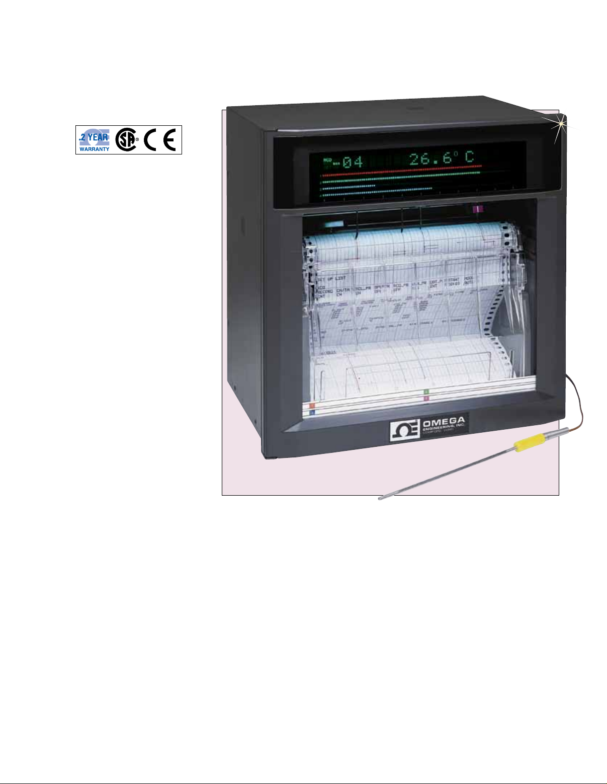
The RD100B 100 mm (4") and
RD1800B 180 mm (7") Series
programmable chart recorders are
easy to use. They feature universal
thermocouple, RTD, and DC voltage
(mV or V) inputs, as well as an analog
bar graph and a digital display.
RD106B with KTSS-18G-12 thermocouple,
sold separately, shown smaller than actual
size. See omega.com
Each recorder can print out—
at programmed intervals or on
demand—the date and time,
channel number, scale marking,
tag number, proper engineering
units, chart speed, alarm value,
and complete program list.
The non-contact, ultrasonic
pen-position transducer is more
accurate than standard pen
mechanisms. The wear-free, brushless
DC servo-motor eliminates the need
for motor brushes, lead wire, and
connectors, and is directly mounted
to the printed circuit board. These
2 features contribute to the long,
trouble-free life of these recorders.
Optional Communication Output
The optional RS422A/RS485
or Ethernet interface lets the
user connect up to 32 units on
a multidrop line to a single host
computer for data logging or input/
output of any setup parameter.
Versatile Alarm and Remote
Control Functions (Optional)
The user can select up to 4 of the
following 6 alarm types: high/low
limit, deviation high/low limit, rate
of change high/low. Optional alarm
relay contact outputs are frontpanel selectable. Also included
is a remote control feature, which
lets the user select any 5 of the
following functions through the front
keypad: recording start/stop; chart
speed change; manual printout
start; message printout start (up to
5 user-defined messages).
S-31
Page 2
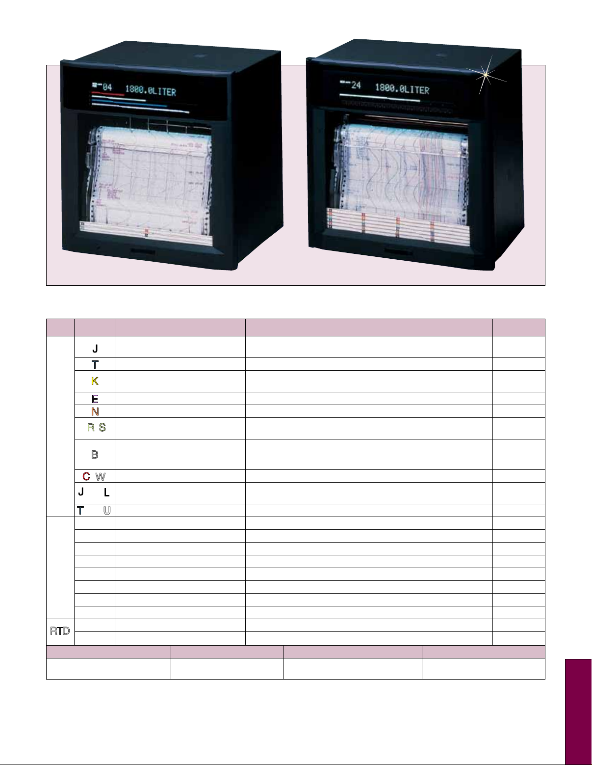
RD1824B shown smaller than actual size.
U
W
Specifications
Input Type* Measurement Range Measurement Accuracy Resolution
J (-328 to -148°F): ±0.15% rdg +0.7°C (1.3°F)
T -200 to 400°C (-328 to 752°F) ±0.15% rdg + 0.5°C (0.9°F) 0.1°C
K (-328 to -148°F): ±0.15% rdg +1.0°C (1.8°F)
E -200 to 800°C (-328 to 1472°F) ±0.15% rdg + 0.5°C (0.9°F) 0.1°C
N 0 to 1300°C (32 to 2372°F) ±0.15% rdg + 0.7°C (1.3°F) 0.1°C
T/C
(6.7°F) and 100 to 300˚C (212 to 572°F) ±1.5˚C (2.7°F)
±0.15% rdg + 0.1°C above 600˚C (0.18°F above 1112°F)
B 0 to 1820°C (32 to 3308°F) 400 to 600°C (752 to 1112°F): ±2.0°C (3.6°F), 0.1°C
not specified below 400˚C (752°F)
C ( W ) 0 to 2315°C (32 to 4199°F) ±0.15% of rdg + 1.0°C (1.8°F) 0.1°C
(-328 to -148°F): ±0.15% rdg +0.7°C (1.3°F)
T DIN( U ) -200 to 400°C (-328 to 752°F) ±0.15% rdg + 0.5°C (0.9°F) 0.1°C
20 mV -20 to 20 mV ±0.1% rdg + 3-digits 10 µV
60 mV -60 to 60 mV ±0.1% rdg + 2-digits 10 µV
2V -20 to 20V ±0.1% rdg + 3-digits 1 mV
6V -60 to 60V ±0.1% rdg + 3-digits 1 mV
20V -20 to 20V ±0.1% rdg + 2-digits 10 mV
50V -50 to 50V ±0.1% rdg + 3-digits 10 mV
1 to 5V 1 to 5V ±0.1% rdg + 2-digits 1 mV
JPt100 -200 to 550°C (-328 to 1022°F) ±0.15% rdg + 0.3°C (0.5°F) 0.1°C
J DIN( L ) -200 to 900°C (-328 to 1652°F)
200 mV -200 to 200 mV ±0.1% rdg + 2-digits 100 µV
Vdc
Pt100 -200 to 600°C (-328 to 1112°F) ±0.15% rdg + 0.3°C (0.5°F) 0.1°C
RTD
-200 to 1100°C (-328 to 2012°F)
-200 to 1370°C (-328 to 2498°F)
R/S 0 to 1760°C (32 to 3200°F)
±0.15% rdg + 0.5°C (0.9°F); -200 to -100°C
±0.15% rdg + 0.7°C (1.3°F); -200 to -100°C
±0.15% rdg + 0.1°C (0.2°F); 0 to 100˚C (32 to 212°F) ±3.7˚C
±0.15% rdg + 0.5°C (0.9°F); -200 to -100°C
0.1°C
0.1°C
0.1°C
0.1°C
Input Range Measurement Limit
Digital input
(operation recording) 2.4 or more: on (TTL) contact on/off
Note: Thermocouple Type J, K, T, E R, S, B: ANSI, IEC 584, DIN IEC 584, JIS C 1602-1981; Type N: nicrosil-nisil, IEC 584, DIN IEC 584;
*
Type C W5%-R/W-26%; J DIN, T DIN: DIN 43760.
Pt100: JIS C 1604-1989, JIS C 1606-1989, IEC 751, DIN IEC 751.
JPt100 JIS C 1604-1981, JIS C 1606-1989.
Input only
Less than 2.4V: off; Contact inputs;
S
S-32
Page 3
General Specifications
Dimensions:
RD1800B: 288 W x 288 H x 220 mm D
(11.4 x 11.4 x 8.66")
RD100B: 144 W x 144 H x 220 mm D
(5.67 x 5.67 x 8.66")
Weight:
RD1800B: 6 dot, 8.4 kg (20 lb);
24 dot, 9.0 kg (20 lb) approx
RD100B: 1 pen, 2.1 kg (4.5 lb);
2 pen, 3.4 kg (7.5 lb); 3 pen, 3.6 kg
(7.9 lb); 4 pen, 2.4 kg (6.9 lb);
6 dot, 2.5 kg (5.5 lb) approx
Case: Drawn steel
Front Door: Aluminum die casting
Panel Thickness:
2 x 26 mm (0.078 x 1.02")
Power: 90 to 132, 180 to 250 Vac,
50/60 Hz standard
Maximum Power Consumption:
Approximately 40 VA
Ambient Temperature
and Humidity: 0 to 50°C (32 to 122°F),
20 to 80% RH @ 5 to 40°C (41 to 104°F)
Memory Backup: Lithium battery
Input
Reference Junction Accuracy:
Type J, K, T, E, N, J DIN, T DIN: ±0.5°C;
Type R, S, B, C: ±1°C
Temperature Coefficients:
Effect of ambient temperature
of 10°C (50°F)
Digital Display:
Within ±0.1% rdg + 1 digit
Recording: Within digital
display ±0.2% of recording span
(excluding reference junction)
Performance Under Reference
Operating Conditions:
Temperature:
23 ±2°C (73 ±3.6°F)
Humidity: 55 ±10%
Usable Power Voltage: 90 to 132 or
180 to 264 Vac, 50/60 Hz
Warm-Up Time: 30 minutes
Measurement Intervals:
Pen Models: 125 ms/channel
Dot Models: RD100B: 1 s/6 channels;
RD1800B: 2.5 s/6 channels
Input Resistance: DC voltage 200 mV
and lower ranges; T/C ranges: 10 MΩ
min; DC voltage 2V and higher ranges:
approx 1 MΩ
Input Bias Current: 10 nA max
(approximately 100 nA on a
thermocouple input if burnout detection
selected)
Thermocouple Burnout Detection:
On/off programmable for each channel or
more detected as open circuit
1 to 5 V Burnout: Less than 0.2V
Maximum Input Voltage: 200 mV or
lower and TC, RTS, DI ranges: ±10 Vdc
continuous; 2 Vdc or greater:
±6 Vdc continuous
Recording System
Recording Span:
RD100B: 100 mm
RD1800B: 180 mm
Pen-Writing: Disposable felt pens
(analog
recording), plotter pens
(digital recording)
Dot Printing:
6-color wire dot recording
Recording Paper:
RD1800: 20 m Z-fold chart
RD100B: 16 m Z-fold chart
Step Response Time:
RD1800: 1.5 s
RD100B: 1 s max
Deadband: Pen models
0.2% of recording span max
Maximum Recording
Resolution: Dot-printing models 0.1 mm
Recording Format:
Normal, zone and partial recording
Chart Speed:
Pen Models: 5 to 12,000 mm/h
(82 increments)
Dot-Printing Models: 1 to 1500 mm/h
(1 mm steps)
Analog Recording Cycles:
Pen Models: Continuous
Dot Printing Models: 6 dots/10 s;
12 dots/15 s; 18 dots/20 s,
24 dots/30 s max
Print Cycle Time—Dot Printing
Models: Auto mode chart speed
determines analog recording cycle rate;
fix mode recording is done at fastest
analog recording interval
Chart Speed Accuracy: Less than
±0.1% (chart running more than
1000 mm continuously and related
to grid of the paper)
Message Printout:
5 messages, date/time and message
up to 16 characters
Periodic Printout: Engineering units
(up to 6 alphanumeric), tag marker
(up to 7 alphanumeric), scale marker
(0/100%), the measured data print
List Printout:
Prints listing of range settings, alarm
settings and other parameters
Manual Printout: Provides a digital
printout of measured results
Display System
Display:
RD100B: VFD 254 x 406 mm
(10 x 16") dot matrix
RD1800B: 457 x 406 mm
(18 x 16") dot matrix
Display: Selectable display screen
Bar Graph Display: Measured value is
1% resolution, left-reference or
center-zero bar graph display (individually
programmable for each channel)
Alarms:
Display: Alarm setting level indicator;
channel number (dot-matrix
models only)
Levels: 4 levels/channel
Types: High, low, high rate of
change, low rate of change, delta
high, delta low (rate of change
alarm time interval: measurement
interval x 1 to 15)
Indications: Shared alarm indicator
flashes; in dot-printing models, alarm
status of alarm channel is
also displayed
Recording: Prints channel number,
alarm type and time on or off on right
side of chart
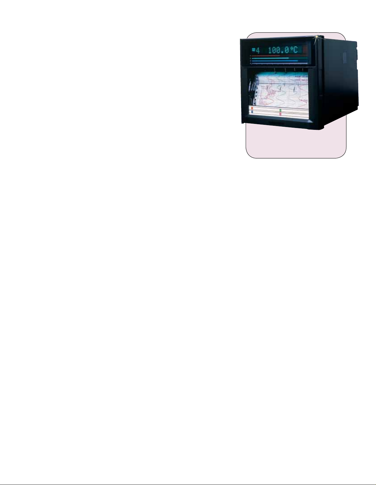
RD1804B shown smaller
than actual size.
Optional Alarm Relay Contact
Output and Remote Control
Alarm Relays: 2, 4, 6 (all units),
12 and 24 points (RD1800 only);
outputs programmable; energize or
de-energize (all relays); hold or non-hold
Remote Control: Enables any mix of
the following to be assigned to 5 contact
inputs: output programmable, recording
start/stop; chart speed change; manual
printout start; alarm acknowledge,
time adjust; computation start/stop,
computation restate; message printout
start (up to 5)
Input Signal: TTL, open collector,
contact
Input Signal Width: 1 second minimum
Contact Capacity: 3 A @ 250 Vac;
0.1 A @ 250 Vdc resistive load
Optional Communication
Output
RS422A/RS485: Conforms to EIA
RS422A; can be used to output
measured values, input and output setup
parameters
Addresses: 1 to 32
Asynchronous:
Start-stop synchronization
Communication System: Half duplex
Wiring: 5-wire
Data Length: 7 or 8-bit
Parity: odd, even or none
Communication Rate: 1200, 2400,
4800, 9600, 19,200, 38,400 baud
Communication Mode:
ASCII or binary (measured data only)
Communication Distance: 1.2 km
Ethernet Interface: Electrical and
mechanical conformance to IEE8023
Transmission Media: 10 Base-T
Protocol: TCP, IP, UDP, ICMP, ARP
CE Option: Meets European
standards for EMI interference
S-33
Page 4
To Order
Visit omega.com /rd100b_rd1800b for Pricing and Details
Input Recording
Model No. Channels Type
RD101B 1 100 mm (4") continuous
RD102B 2 100 mm (4") continuous
RD103B 3 100 mm (4") continuous
RD104B 4 100 mm (4") continuous
RD106B 6 100 mm (4") dot
RD1801B 1 180 mm (7") continuous
RD1802B 2 180 mm (7") continuous
RD1803B 3 180 mm (7") continuous
RD1804B 4 180 mm (7") continuous
RD1806B 6 180 mm (7") dot
RD1812B 12 180 mm (7") dot
RD1818B 18 180 mm (7") dot
RD1824B 24 180 mm (7") dot
Comes complete with 1 pen per channel, 1 pack of paper, mounting
brackets and operator’s manual.
Ordering Examples: RD104B, 4-pen recorder with 4-alarm relays.
OCW-3, OMEGACARESM extends standard 2-year warranty to a total
of 5 years.
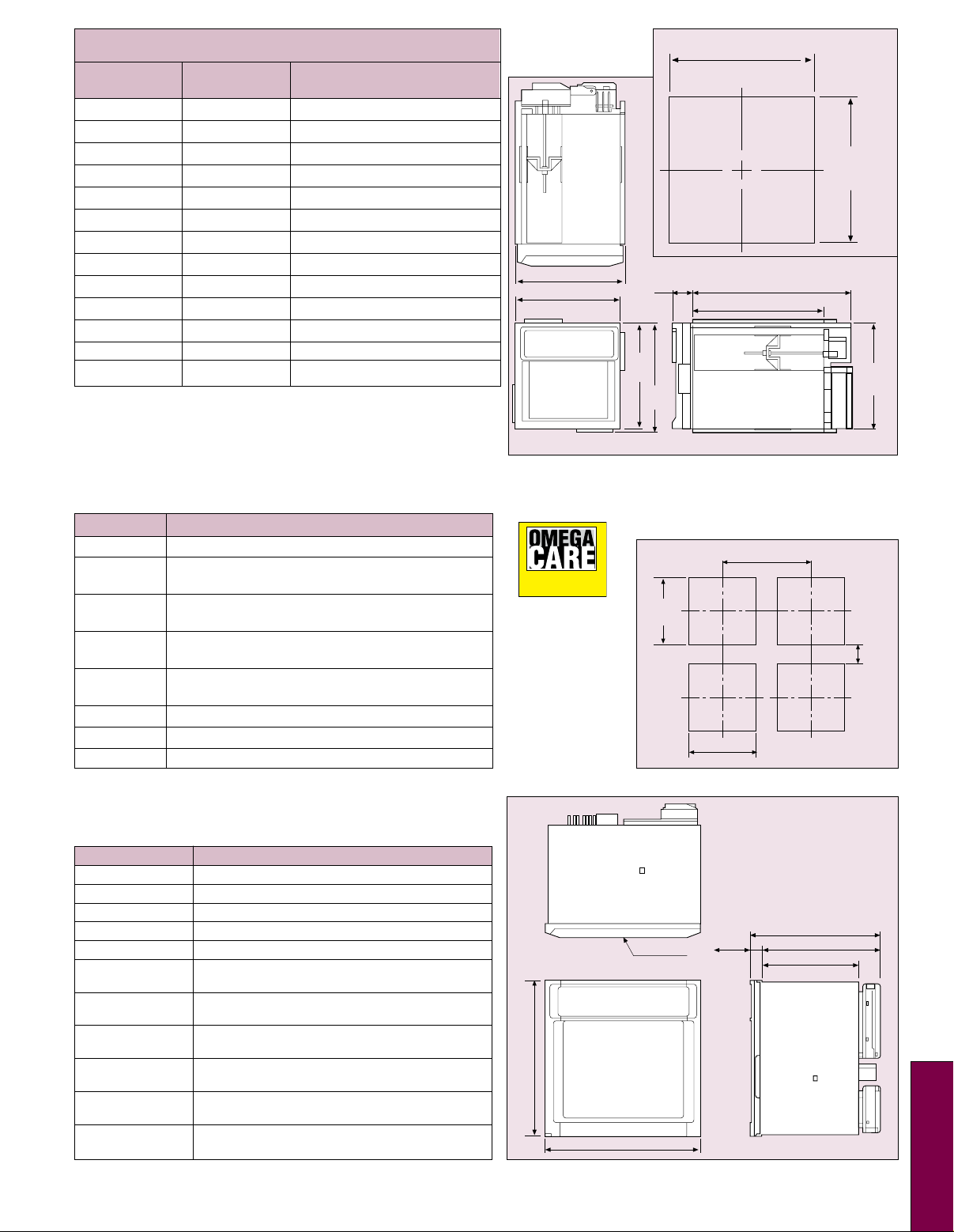
RD100B
Panel Cutout
151.5 (5.96)
144 (5.67)
(1.08)
144
(5.67)
27.5
151.5
(5.96)
+2
137
-0
(5.39)
137
(5.39)
Dimensions: mm (inch)
220 (8.66)
178 (7.01)
+2
-0
136.5
(5.37)
Options (Not Field Installable)
Suffix No. Description
/A1/R1 2-alarm outputs, remote control
/A2/R1 4-alarm outputs, remote control
(RD100A Series only)
/A3/R1 6-alarm outputs, remote control
(RD106A and RD1800 Series)
/A4/R1 12-alarm outputs, remote control (RD1806,
RD1812, RD1818, RD1824 only)
/A5/R1 24-alarm outputs, remote control
(RD1824 only)
/C3 RS422A communications
24V 24 Vdc power (not available on portable unit)
/C7 Ethernet interface, 10 Base-T
Accessories
Model No. Description
RD10 0A-01 Disposable red felt pen channel-1
RD10 0A-02 Disposable green felt pen channel-2
RD10 0A-03 Disposable blue felt pen channel-3
RD10 0A-04 Disposable violet felt pen channel-4
RD100 A-11 Plotter pen
RD100B-SW1 Configuration software for models with
RD100B-SW2 Configuration software for models
RD10 0-RC 6-color print ribbon purple, red, green,
RD110-RC 6-color print ribbon for RD1806,
RD100 -ZFP-1 Z-fold chart paper (pkg of 1)
RD110-Z FP Z-fold chart paper (pkg of 1)
communication interface
without communication interface
blue, brown, black (RD106 only)
RD1812, RD1818 and RD1824
100 mm x 16 m (4" x 52') RD100A Series
180 mm x 20 m (7" x 65') RD1800 Series
SM
Extended Warranty
Program
OMEGACARESM
extended warranty
program is available
for models shown on
this page.
OMEGACARESM
covers parts, labor
and equivalent
loaners. Ask your
sales representative
for full details when
placing an order.
228 (11.34)
228
RD1800B Panel Cutout
360
(14.17)
+2
0
281
(11.06)
+2
281
0
(11.06)
Dimensions:
mm (inch)
25
DOOR
(11.34)
(0.98)
182.3 (7.18)
245 (9.65)
220 (8.66)
80
(3.15)
S
S-34
 Loading...