

Omega Products PX-271A Installation Manual
Pneumatic Pressure Transducer
PX-271A
M3504/0303
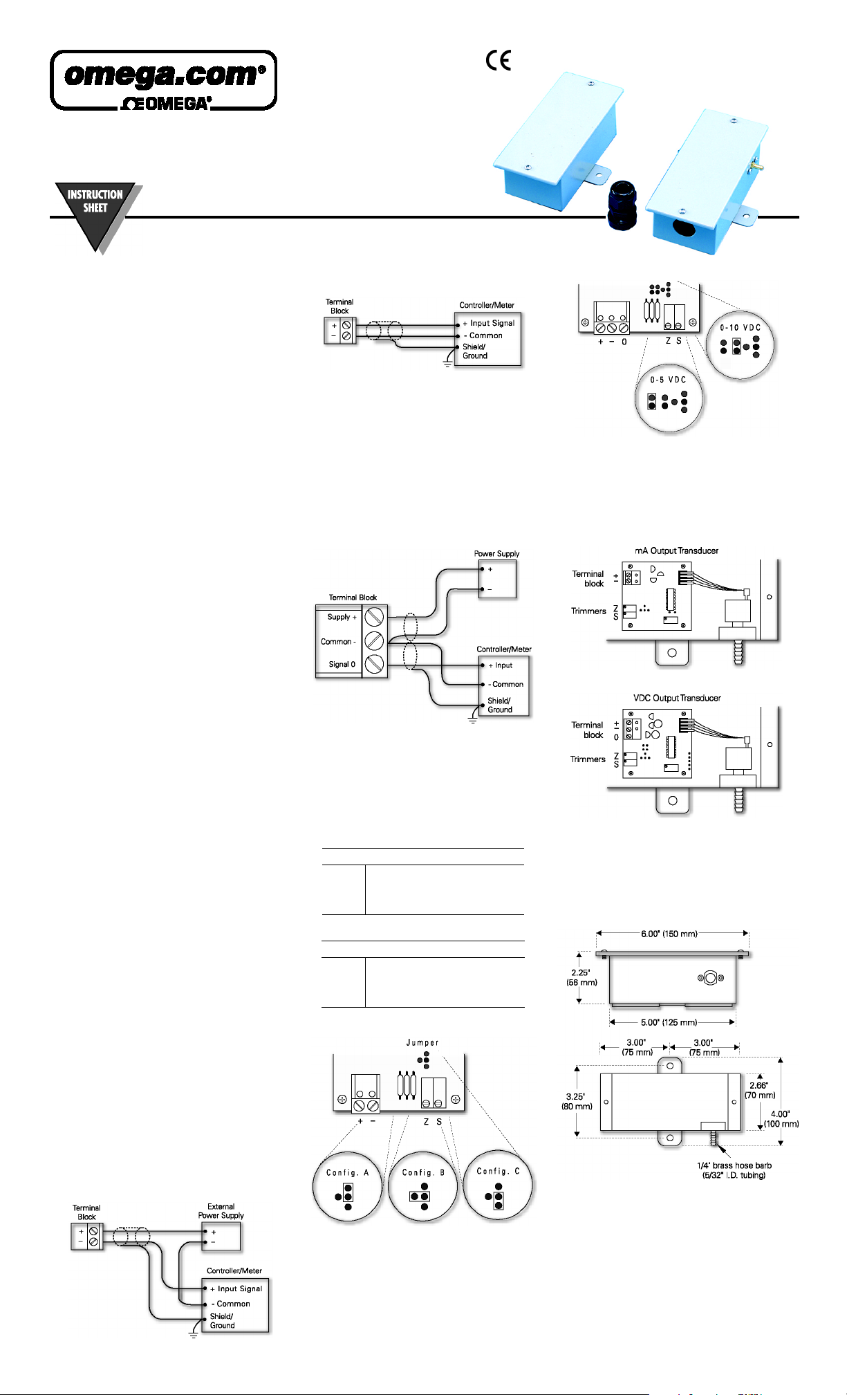
4. If using a controller/ meter with an internal power
SPECIFICATIONS
Accur acy*: ± 1%
Maximum Pressure: 40
Supply Voltage: 12 - 40
transducers only)
Supply Current: 10 MA maximum
20 MA maximum MA output tran sducers
Enclosure: 18 Ga. C.R. steel NEMA-4 (IP-65)
Finish: Baked on enamel PMS2GR88B
Conformance: EMC standards EN50082-1(1992),
EN55014(1993)/EN60730-1(1992)
Compensated Temperature Range: 0°F to 180°F (18°C to
82°C)
T. C . E rr o r: ± 0.025%/°F (.03%/°C)
Media Compatibility: Clean dry air or any inert gas
Port Connection: 5/32” I.D.; ¼” O.D. hose barb
Environmental: 10 to 90% RH non-condensing
Te rm in a ti o n: Unpluggable screw terminal block
Wire Size: 12 Ga. maximum
Load Impedance: 1.6K ohms maximum at 40
transducers); 1,000 ohms minimum (
Weight: 1.0 lb. (.45 kg)
*
Includes nonlinearity, hysteresis, and non-repeatability.
FS
PSIG
; 12 - 35
VDC
VDC
VDC
output transd ucers;
output transducers)
VAC (VDC
(
VDC
output
output
M
A
supply, make these connections:
• controller/meter input signal to the [+] terminal
• controller/meter common to the [-] terminal
5. Reinsert the terminal block onto the circuit board and
apply power to the transducer.
6. Check for the appropriate output signal using a digital
voltmeter set to DC milliamps connected in series to
the [-] term inal.
Wiring for VDC Output:
1. Remove the blue terminal block by carefully pulling it
off the circuit board.
2. Note the block’s terminal markings on the circuit board.
3. Connect the power supply voltage wire to the [+]
terminal and the power sup ply common to the [-]
terminal.
4. Connect the controller/meter input wire to the [0]
terminal and the controller/meter common wire to the
[-] terminal.
Jumper Confi gurations for VDC Outp ut
CALIBRATION
All transducers are factory calibrated to meet or exceed
published specifications. If field adjustment is necessary,
follow these instructions.
1. Connect the [+ ] and [-] termina ls to the appropr iate
power source.
2. If calibrating an
voltmeter in series to the [-] terminal.
output transducer, connect a digital
M
A
INSTALLATION PRECAUTIONS
Do not use on oxygen service, in an explosive or hazardous
environment, or with flammable or combustible material.
Disconnect the power supply before installing the transducer.
Failure to do so can result in electrical shock and equipment
damage.
Make all connections in accordance with the job wiring
diagram and national and local electrical codes.
Use electrostatic discharge precautions such as wrist straps
when installing and wiring the transducer.
Do not exceed ratings for the transducer.
If using grounded AC, ensure that the hot wire is on the [+]
terminal. Also, if using a controller without built-in isolation,
use an isolation transformer to supply the transducer.
This transducer contains a half-wave rectifier power supply
and must not be powered from transformers powering other
devices with non-isolated full-wave rectifier power supplies.
When multiple transducers are powered from the same
transformer, damage will result unless all 24-gage power
leads are connected to the same power lead on all
transducers. Maintain the correct phasing when powering
more than one transducer from a single transformer.
WIRING
Use 12
¼-inch O.D. (5/32-inch I.D.) tubing for pressure connections.
The
powered with a 12 - 40
pneumatic pressure transducer is field selectable for 0 - 5
or 0 - 10
VDC
wire maximum for wiring terminals and flexible
AWG
output pneumatic pressure transducer must be
M
A
output and can be powered with either 12 - 40
VDC
or 12 - 35
VAC
.
power supply. The
VDC
VDC
output
VDC
5. Reinsert the terminal block onto the circuit board and
apply power to the transducer.
6. Check the appropriate VDC output using a di gital
voltmeter set to DC volts connected to the [0] and [-]
terminals.
PRESSURE RANGES AND JUMPER
CONFIGURATIONS
Jumper Configurations for mA Output Transducers
Range A B C
020 0 - 20
030 0 - 30
X15 3 - 15
Jumper Configurations for VDC Output Transducers
Range A B C
020 0 - 20
030 0 - 30
X15 — 3 - 15
Jumper Conf igurations for Pr essure Ranges
PSIG
PSIG
PSIG
PSIG
PSIG
0 - 10
0 - 15
PSIG
PSIG
0 - 5
0 - 7.5
PSIG
PSIG
——
0 - 10
0 - 15
PSIG
PSIG
PSIG
0 - 5
0 - 7.5
PSIG
PSIG
—
3. If calibrating a VDC output transducer, connect a digital
voltmeter on DC volts across the [0] and [-] terminals.
4. Apply low pressure to the transducer and carefully
adjust the zero tr immer [Z] to obtain the desired low
output pressure.
5. Apply high pressure to the transducer and adjust the
span trimmer [S] to obtain the desired high output
pressure.
6. Repeat steps 4 and 5 until the transducer is fully
calibrated.
DIMENSIONS
Wiring for mA Output:
1. Remove the blue terminal block by carefully pulling it
off the circuit b oard.
2. Note the block’s terminal markings on the circuit board.
3. If using an external power supply, make these
connections:
• supply voltage wire to the [+] terminal
• power supply common to the common bus of the
controller/meter
• input signal of the controller/meter to the [-]
terminal

Servicing Europe:
OMEGAnet
Service
Online
Internet e-mail
info@omega.com
www.omega.com
Servicing North America:
USA:
ISO 9001 Certified
Canada:
One Omega Drive, P.O. Box 4047
Stamford, CT 06907-0047
TEL: (203) 359-1660 FAX: (203) 359-7700
e-mail: info@omega.com
976 Bergar
Laval (Quebec) H7L 5A1
TEL: (514) 856-6928 FAX: (514) 856-6886
e-mail: info@omega.com
For immediate technical or application
assistance:
USA and Canada:
Mexico:
Sales Service: 1-800-826-6342 / 1-800-TC-OMEGA
Customer Service: 1-800-622-2378 / 1-800-622-BEST
Engineering Service: 1-800-872-9436 / 1-800-USA-WHEN
TELEX: 996404 EASYLINK: 62968934 CABLE: OMEGA
TEL: (001) 800-826-6342 FAX: (001) 203-359-7807
En Espanol: (001) 203-359-7803 e-mail: espanol@omega.com
info@omega.com
Benelux:
Czech Republic:
France:
Germany/Austria:
United Kingdom:
ISO 9002 Certified
SM
SM
SM
SM
Postbus 8034, 1180 LA Amstelveen, The Netherlands
TEL: +31 (0) 20 6418405 FAX: +31 (0) 20 6434643
Toll Free in Benelux: 06 0993344
e-mail: nl@omega.com
Rude armady 1868, 73301 Karvina
TEL: +420 (0) 69 6311899 FAX: +420 (0) 69 6311114
Toll Free in Czech Republic: 0800-1-66342
e-mail: czech@omega.com
9, rue Denis Papin, 78190 Trappes
TEL: +33 (0) 130 621 400 FAX: +33 (0) 130 699 120
Toll Free in France: 0800-4-06342
e-mail: france@omega.com
Daimlerstrasse 26, D-75392 Deckenpfronn, Germany
TEL: +49 (0) 7056 3017 FAX: +49 (0) 7056 8540
Toll Free in Germany: 0800 TC OMEGA
e-mail: germany@omega.com
P.O. Box 7, Omega Drive
Irlam, Manchester
M44 5EX, United Kingdom
TEL: +44 (0) 161 777-6611 FAX: +44 (0) 161 777-6622
Toll Free in England: 0800 488 488
e-mail: sales@omega.co.uk
SM
It is the policy of OMEGA to comply with all worldwide safety and EMC/EMI regulations that apply. OMEGA is constantly
pursuing certification of its products in the European New Approach Directives. OMEGA will add the CE mark to every
appropriate device upon certification.
The information contained in this document is believed to be correct but OMEGA Engineering, Inc. accepts no liability for any errors it contains,
and reserves the right to alter specifications without notice.
WARNING: These products are not designed for use in, and should not be used for, patient connected applications.
WARRANTY/DISCLAIMER
OMEGA ENGINEERING, INC. warrants this unit to be free of defects in materials and workmanship for a period of 13 months from date of purchase. OMEGA
Warranty adds an additional one (1) month grace period to the normal one (1) year product warranty to cover handling and shipping time. This ensures that
OMEGA’s customers receive maximum coverage on each product.
If the unit should malfunction, it must be returned to the factory for evaluation. OMEGA’s Customer Service Department will issue an Authorized Return (AR) number
immediately upon phone or written request. Upon examination by OMEGA, if the unit is found to be defective, it will be repaired or replaced at no charge. OMEGA’s
WARRANTY does not apply to defects resulting from any action of the purchaser, including but not limited to mishandling, improper interfacing, operation outside
of design limits, improper repair, or unauthorized modification. This WARRANTY is VOID if the unit shows evidence of having been tampered with or shows
evidence of having been damaged as a result of excessive corrosion; or current, heat, moisture or vibration; improper specification; misapplication; misuse or other
operating conditions outside of OMEGA’s control. Components which wear are not warranted, including but not limited to contact points, fuses, and triacs.
OMEGA is pleased to offer suggestions on the use of its various products. However, OMEGA neither assumes responsibility for any omissions or
errors nor assumes liability for any damages that result from the use of its products in accordance with information provided by OMEGA, either
verbal or written. OMEGA warrants only that the parts manufactured by it will be as specified and free of defects. OMEGA MAKES NO OTHER
WARRANTIES OR REPRESENTATIONS OF ANY KIND WHATSOEVER, EXPRESS OR IMPLIED, EXCEPT THAT OF TITLE, AND ALL IMPLIED
WARRANTIES INCLUDING ANY WARRANTY OF MERCHANTABILITY AND FITNESS FOR A PARTICULAR PURPOSE ARE HEREBY DISCLAIMED.
LIMITATION OF LIABILITY: The remedies of purchaser set forth herein are exclusive, and the total liability of OMEGA with respect to this order,
whether based on contract, warranty, negligence, indemnification, strict liability or otherwise, shall not exceed the purchase price of the
component upon which liability is based. In no event shall OMEGA be liable for consequential, incidental or special damages.
CONDITIONS: Equipment sold by OMEGA is not intended to be used, nor shall it be used: (1) as a “Basic Component” under 10 CFR 21 (NRC), used in or with any
nuclear installation or activity; or (2) in medical applications or used on humans. Should any Product(s) be used in or with any nuclear installation or activity, medical
application, used on humans, or misused in any way, OMEGA assumes no responsibility as set forth in our basic WARRANTY / DISCLAIMER language, and,
additionally, purchaser will indemnify OMEGA and hold OMEGA harmless from any liability or damage whatsoever arising out of the use of the Product(s) in such a
manner.
RETURN REQUESTS/INQUIRIES
Direct all warranty and repair requests/inquiries to the OMEGA Customer Service Department. BEFORE RETURNING ANY PRODUCT(S) TO OMEGA, PURCHASER
MUST OBTAIN AN AUTHORIZED RETURN (AR) NUMBER FROM OMEGA’S CUSTOMER SERVICE DEPARTMENT (IN ORDER TO AVOID PROCESSING DELAYS). The
assigned AR number should then be marked on the outside of the return package and on any correspondence.
The purchaser is responsible for shipping charges, freight, insurance and proper packaging to prevent breakage in transit.
FOR WARRANTY
available BEFORE contacting OMEGA:
1.
Purchase Order number under which the product was
PURCHASED,
2.
Model and serial number of the product under warranty, and
3.
Repair instructions and/or specific problems relati ve to the
product.
OMEGA’s policy is to make running changes, not model changes, whenever an improvement is possible. This affords our customers the latest
in technology and engineering.
OMEGA is a registered trademark of OMEGA ENGINEERING, INC.
© Copyright 2003 OMEGA ENGINEERING, INC. All rights reserved. This document may not be copied, photocopied, reproduced, translated, or
reduced to any electronic medium or machine-readable form, in whole or in part, without the prior written consent of OMEGA ENGINEERING,
INC.
RETURNS, please have the following information
FOR NON-WARRANTY
charges. Have the following information available BEFORE contacting
OMEGA:
1.
Purchase Order number to cover the COST of the repair,
2.
Model and serial number of the product, and
3.
Repair instructions and/or specific problems relative to the
product.
REPAIRS, consult OMEGA for current repair
 Loading...