

Page 1

User’s Guide
Model PX2088 Pressure Transmitter
http://www.omega.com
e-mail: info@omega.com
Pressure Transmitter
PX2088
Page 2

OMEGAnet® On-Line Service Internet e-mail
http://www.omega.com info@omega.com
Servicing North America:
USA: One Omega Drive, Box 4047
ISO 9001 Certified Stamford, CT 06907-0047
Tel: (203) 359-1660 FAX: (203) 359-7700
e-mail: info@omega.com
Canada: 976 Bergar
Laval (Quebec) H7L 5A1
Tel: (514) 856-6928 FAX: (514) 856-6886
e-mail: info@omega.ca
For immediate technical or application assistance:
USA and Canada: Sales Service: 1-800-826-6342 / 1-800-TC-OMEGASM
Customer Service: 1-800-622-2378 / 1-800-622-BESTSM
Engineering Service: 1-800-872-9436 / 1-800-USA-WHENSM
TELEX: 996404 EASYLINK: 62968934 CABLE: OMEGA
Mexico and
Latin America: Tel: (95) 800-826-6342 FAX: (95) 203-359-7807
En Espan˜ol: (95) 203-359-7803 e-mail: espanol@omega.com
Servicing Europe:
Benelux: Postbus 8034, 1180 LA Amstelveen, The Netherlands
Tel: (31) 20 6418405 FAX: (31) 20 6434643
Toll Free in Benelux: 0800 0993344
e-mail: nl@omega.com
Czech Republic: ul. Rude armady 1868, 733 01 Karvina-Hranice
Tel: 420 (69) 6311899 FAX: 420 (69) 6311114
Toll Free: 0800-1-66342 e-mail: czech@omega.com
France: 9, rue Denis Papin, 78190 Trappes
Tel: (33) 130-621-400 FAX: (33) 130-699-120
Toll Free in France: 0800-4-06342
e-mail: france@omega.com
Germany/Austria: Daimlerstrasse 26, D-75392 Deckenpfronn, Germany
Tel: 49 (07056) 3017 FAX: 49 (07056) 8540
Toll Free in Germany: 0130 11 21 66
e-mail: info@omega.de
United Kingdom: One Omega Drive, River Bend Technology Centre
ISO 9002 Certified Northbank, Irlam, Manchester
M44 5EX, England
Tel: 44 (161) 777-6611 FAX: 44 (161) 777-6622
Toll Free in the United Kingdom: 0800-488-488
e-mail: info@omega.co.uk
It is the policy of OMEGA to comply with all worldwide safety and EMC/EMI regulations that apply. OMEGA is constantly pursuing certification of
its products to the European New Approach Directives. OMEGA will add the CE mark to every appropriate device upon certification.
The information contained in this document is believed to be correct, but OMEGA Engineering, Inc. accepts
no liability for any errors it contains, and reserves the right to alter specifications without notice.
WARNING: These products are not designed for use in, and should not be used for, patient-connected applications.
Page 3

Table of Contents
SECTION 1
Introduction
Overview . . . . . . . . . . . . . . . . . . . . . . . . . . . . . . . . . . . . . . . . . . . . . . . . . . . . . . . . 1-1
Safety Messages . . . . . . . . . . . . . . . . . . . . . . . . . . . . . . . . . . . . . . . . . . . . . . . . . . 1-1
Safety Notice . . . . . . . . . . . . . . . . . . . . . . . . . . . . . . . . . . . . . . . . . . . . . . . . . . . . . 1-1
Models Covered . . . . . . . . . . . . . . . . . . . . . . . . . . . . . . . . . . . . . . . . . . . . . . . . . . . 1-2
Using This Manual . . . . . . . . . . . . . . . . . . . . . . . . . . . . . . . . . . . . . . . . . . . . . . . . 1-2
SECTION 2
Commissioning the Smart Transmitter
Overview . . . . . . . . . . . . . . . . . . . . . . . . . . . . . . . . . . . . . . . . . . . . . . . . . . . . . . . . 2-1
Safety Messages . . . . . . . . . . . . . . . . . . . . . . . . . . . . . . . . . . . . . . . . . . . . . . . . . . 2-1
Commission: On the Bench or In the Loop . . . . . . . . . . . . . . . . . . . . . . . . . . . . . 2-2
Set up the Transmitter and the Communicator . . . . . . . . . . . . . . . . . . . . . 2-2
Review Configuration Data . . . . . . . . . . . . . . . . . . . . . . . . . . . . . . . . . . . . . . . . . 2-3
Review . . . . . . . . . . . . . . . . . . . . . . . . . . . . . . . . . . . . . . . . . . . . . . . . . . . . . . 2-3
Check Output . . . . . . . . . . . . . . . . . . . . . . . . . . . . . . . . . . . . . . . . . . . . . . . . . . . . 2-3
Process Variables . . . . . . . . . . . . . . . . . . . . . . . . . . . . . . . . . . . . . . . . . . . . . . 2-3
Basic Setup . . . . . . . . . . . . . . . . . . . . . . . . . . . . . . . . . . . . . . . . . . . . . . . . . . . . . . 2-4
Tag . . . . . . . . . . . . . . . . . . . . . . . . . . . . . . . . . . . . . . . . . . . . . . . . . . . . . . . . . 2-4
Output Units . . . . . . . . . . . . . . . . . . . . . . . . . . . . . . . . . . . . . . . . . . . . . . . . . 2-4
Rerange . . . . . . . . . . . . . . . . . . . . . . . . . . . . . . . . . . . . . . . . . . . . . . . . . . . . . 2-5
Damping . . . . . . . . . . . . . . . . . . . . . . . . . . . . . . . . . . . . . . . . . . . . . . . . . . . . . 2-6
Detailed Setup . . . . . . . . . . . . . . . . . . . . . . . . . . . . . . . . . . . . . . . . . . . . . . . . . . . 2-6
Meter Setup . . . . . . . . . . . . . . . . . . . . . . . . . . . . . . . . . . . . . . . . . . . . . . . . . . 2-6
Burst Mode . . . . . . . . . . . . . . . . . . . . . . . . . . . . . . . . . . . . . . . . . . . . . . . . . . 2-6
Save, Recall, or Clone Configuration Data . . . . . . . . . . . . . . . . . . . . . . . . . 2-7
Enable or Disable Local Span and Zero Buttons . . . . . . . . . . . . . . . . . . . . . 2-7
Calibration . . . . . . . . . . . . . . . . . . . . . . . . . . . . . . . . . . . . . . . . . . . . . . . . . . . . . . 2-8
Calibration Overview . . . . . . . . . . . . . . . . . . . . . . . . . . . . . . . . . . . . . . . . . . 2-8
Sensor Trim . . . . . . . . . . . . . . . . . . . . . . . . . . . . . . . . . . . . . . . . . . . . . . . . . . 2-9
Output Trim . . . . . . . . . . . . . . . . . . . . . . . . . . . . . . . . . . . . . . . . . . . . . . . . . . 2-11
Diagnostics and Service . . . . . . . . . . . . . . . . . . . . . . . . . . . . . . . . . . . . . . . . . . . . 2-12
Multidrop Communication . . . . . . . . . . . . . . . . . . . . . . . . . . . . . . . . . . . . . . . . . . 2-13
i
Page 4

SECTION 3
Commissioning the Analog Transmitter
Overview . . . . . . . . . . . . . . . . . . . . . . . . . . . . . . . . . . . . . . . . . . . . . . . . . . . . . . . . 3-1
Safety Messages . . . . . . . . . . . . . . . . . . . . . . . . . . . . . . . . . . . . . . . . . . . . . . . . . . 3-1
Commission: On the Bench or In the Loop . . . . . . . . . . . . . . . . . . . . . . . . . . . . . 3-2
Test Terminals . . . . . . . . . . . . . . . . . . . . . . . . . . . . . . . . . . . . . . . . . . . . . . . . . . . 3-2
Zero and Span Adjustments . . . . . . . . . . . . . . . . . . . . . . . . . . . . . . . . . . . . . . . . . 3-3
Selector Switch . . . . . . . . . . . . . . . . . . . . . . . . . . . . . . . . . . . . . . . . . . . . . . . 3-3
Potentiometer Adjustment . . . . . . . . . . . . . . . . . . . . . . . . . . . . . . . . . . . . . . 3-4
Setting the Zero . . . . . . . . . . . . . . . . . . . . . . . . . . . . . . . . . . . . . . . . . . . . . . . 3-4
Setting the Span . . . . . . . . . . . . . . . . . . . . . . . . . . . . . . . . . . . . . . . . . . . . . . 3-5
SECTION 4
Installation
Overview . . . . . . . . . . . . . . . . . . . . . . . . . . . . . . . . . . . . . . . . . . . . . . . . . . . . . . . . 4-1
Safety Messages . . . . . . . . . . . . . . . . . . . . . . . . . . . . . . . . . . . . . . . . . . . . . . 4-1
Installation . . . . . . . . . . . . . . . . . . . . . . . . . . . . . . . . . . . . . . . . . . . . . . . . . . . . . . 4-3
Installation Procedures . . . . . . . . . . . . . . . . . . . . . . . . . . . . . . . . . . . . . . . . . . . . 4-3
Model PX2088 . . . . . . . . . . . . . . . . . . . . . . . . . . . . . . . . . . . . . . . . . . . . . . . . 4-3
Wiring Connections PX2088 . . . . . . . . . . . . . . . . . . . . . . . . . . . . . . . . . . . . . 4-8
Power Supply . . . . . . . . . . . . . . . . . . . . . . . . . . . . . . . . . . . . . . . . . . . . . . . . . 4-10
Failure Mode and Security Jumpers . . . . . . . . . . . . . . . . . . . . . . . . . . . . . . . . . . 4-11
Failure Mode . . . . . . . . . . . . . . . . . . . . . . . . . . . . . . . . . . . . . . . . . . . . . . . . . 4-11
Transmitter Security . . . . . . . . . . . . . . . . . . . . . . . . . . . . . . . . . . . . . . . . . . . 4-12
Zero and Span Adjustments . . . . . . . . . . . . . . . . . . . . . . . . . . . . . . . . . . . . . . . . . 4-12
Rerange Procedure . . . . . . . . . . . . . . . . . . . . . . . . . . . . . . . . . . . . . . . . . . . . 4-13
SECTION 5
Troubleshooting
Troubleshooting . . . . . . . . . . . . . . . . . . . . . . . . . . . . . . . . . . . . . . . . . . . . . . . . . . 5-2
ii
Page 5

SECTION 6
Spare Parts and Ordering
Spare Parts . . . . . . . . . . . . . . . . . . . . . . . . . . . . . . . . . . . . . . . . . . . . . . . . . . . . . . 6-1
SECTION 7
LCD Meter
LCD Meter for Smart Transmitters . . . . . . . . . . . . . . . . . . . . . . . . . . . . . . . . . . 7-1
Diagnostic Messages . . . . . . . . . . . . . . . . . . . . . . . . . . . . . . . . . . . . . . . . . . . 7-2
LCD Meter for Analog Transmitters . . . . . . . . . . . . . . . . . . . . . . . . . . . . . . . . . . 7-4
Diagnostic Message Display . . . . . . . . . . . . . . . . . . . . . . . . . . . . . . . . . . . . . . . . 7-5
Installation . . . . . . . . . . . . . . . . . . . . . . . . . . . . . . . . . . . . . . . . . . . . . . . . . . . . . . 7-5
Configuration . . . . . . . . . . . . . . . . . . . . . . . . . . . . . . . . . . . . . . . . . . . . . . . . . . . . 7-6
Positioning the Decimal Point . . . . . . . . . . . . . . . . . . . . . . . . . . . . . . . . . . . 7-7
Scaling the Display . . . . . . . . . . . . . . . . . . . . . . . . . . . . . . . . . . . . . . . . . . . . 7-7
iii
Page 6

APPENDIX A
Model HC275 HART
Communicator
Overview . . . . . . . . . . . . . . . . . . . . . . . . . . . . . . . . . . . . . . . . . . . . . . . . . . . . . . . . A-1
Safety Messages . . . . . . . . . . . . . . . . . . . . . . . . . . . . . . . . . . . . . . . . . . . . . . . . . . A-1
Menu Tree . . . . . . . . . . . . . . . . . . . . . . . . . . . . . . . . . . . . . . . . . . . . . . . . . . . A-2
Fast Key Sequences . . . . . . . . . . . . . . . . . . . . . . . . . . . . . . . . . . . . . . . . . . . . . . . A-3
iv
Page 7

SECTION
1
Introduction
OVERVIEW
This section contains general transmitter safety information, a brief description of
each model covered in this manual, and a summary of each of each section.
SAFETY MESSAGES
Procedures and instructions in this manual may require special precautions to
ensure the safety of the personnel performing the operations.
SAFETY NOTICE
The following performance limitations may inhibit efficient or safe operation. Critical
applications should have appropriate diagnostic and backup systems in place.
Pressure transmitters contain an internal fill fluid. It is used to transmit the process pressure
through the isolating diaphragms to the pressure sensing element. In rare cases, oil leak paths
in oil-filled pressure transmitters can be created. Possible causes include: physical damage to
the isolator diaphragms, process fluid freezing, isolator corrosion due to an incompatible
process fluid, etc.
A transmitter with an oil fill fluid leak can continue to perform normally for a period of time.
Sustained oil loss will eventually cause one or more of the operating parameters to exceed
published specifications while a small drift in operating point output continues. Symptoms of
advanced oil loss and other unrelated problems include:
nSustained drift rate in true zero and span or operating point output or both
nSluggish response to increasing or decreasing pressure or both
nLimited output rate or very nonlinear output or both
nChange in output process noise
nNoticeable drift in operating point output
nAbrupt increase in drift rate of true zero or span or both
nUnstable output
nOutput saturated high or low
1-1
Page 8

MODELS COVERED
Model PX2088 Smart and Analog Absolute or Gage Pressure Transmitter
measures absolute or gage pressure ranges from 0–1 to 0–4,000 psi
(0–6.9 to 0–27579 kPa) using a patented piezoresistive silicon sensor.
Mounts directly to the process pipe or to the optional mounting bracket.
USING THIS MANUAL
This manual provides information for the Omega Model PX2088
Pressure Transmitter. It is organized into the following sections:
Section 2 Commissioning the Smart Transmitter
This section provides information on commissioning and operating the Model PX2088
Smart Pressure Transmitter. Information is also included on software functions,
configuration parameters, and on-line variables.
Section 3 Commissioning the Analog Transmitter
This section provides information on commissioning and operating the Model PX2088
Analog Pressure Transmitter.
Section 4 Installation
This section provides installation procedures, wiring diagrams, and information
about transmitter load limitations and power supply requirements.
Section 5 Troubleshooting
This section provides basic troubleshooting suggestions to help solve the most
common operating problems.
Section 6 Reference Data
This section provides reference data including ambient temperature effects, spare
parts, and typical transmitter model structures.
Secton 7 LCD Meter
This section provides installation and operation information for the optional LCD
Meter.
Appendix B HART Communicator
menu tree and fast key sequences for HART Communicator
1-2
Page 9
SECTION
2 Commissioning the Smart
Transmitter
OVERVIEW
This section contains information regarding commissioning the transmitter.
Commissioning involves reviewing configuration data, setting the 4 and 20 mA
points, configuring the transmitter to recognize accessories such as a LCD meter,
and testing the transmitter output.
SAFETY MESSAGES
This section contains procedures that require connecting a communicator to the
transmitter, or making connections in an explosive atmosphere. The following safety
messages apply to all procedures throughout this section requiring cover removal
and communicator connection to the transmitter terminal block. Keep the following
safety messages in mind whenever you perform an operation requiring cover
removal or the connection of a communicator to a measurement loop.
Warnings
Explosions could result in death or serious injury:
nDo not remove the transmitter covers in explosive atmospheres
when the circuit is alive.
nBefore connecting a HART-based communicator in an explosive atmosphe re,
make sure the instruments in the loop are installed in accordance with
intrinsically safe or non-incendive field wiring practices.
nBoth transmitter covers must be fully engaged to meet
explosion-proof requirements.
High voltage that may be present on leads could cause electrical shock:
nAvoid contact with leads and terminals.
2-1
Page 10

COMMISSION: ON THE BENCH OR IN THE LOOP
Commission the Model PX2088 Smart Transmitter before or after installation.
It may be useful to commission the transmitter on the bench before
installation to ensure proper operation, to familiarize yourself with transmitter
functionality, and to avoid exposing the transmitter electronics to the plant
environment. Commissioning consists of reviewing configuration data, setting
output units, setting the 4 and 20 mA points, configuring the transmitter for any
non-standard accessories or functions, and testing the transmitter output.
Set up the Transmitter and the Communicator
To configure the transmitter on the bench, connect the transmitter and the
communicator as shown in Figure 2-1. To power the transmitter you will need a
power supply capable of providing 10.5 to 36.0 V dc and a meter to measure output
current. To enable communication, a resistance of at least 250 ohms must be present
between the communicator loop connection and the power supply. You can connect the
communicator leads at any termination point in the signal loop, but it is most
convenient to connect them to the terminals labeled “COMM” on the terminal block.
After you con nec t th e b ench equipm e nt a s s h ow n in Figure 2-1, turn on the
communicator by pressing the ON/OFF key. The communicator will search for a
HART-compatible device and will indicate that the connection is made. If the
connection is not made, the communicator will indicate that no device was found.
FIGURE 2-1. Connecting a Communicator to a Transmitter Loop
RL≥ 250 V
Power
Supply
The signal loop may be grounded
at any single point in the loop, or
may be left ungrounded
2088S-2088C02C
If the communicator lacks the device driver for the PX2088 Smart, the transmitter will
be identified as “GENERIC” by the communicator. Basic configuration functions are
still possible, but many advanced configuration functions are not possible when the
communicator is in this mode. Contact Omega customers service for assistance
in obtaining the PX2088 Smart device driver for the HART Communicator.
2-2
Page 11
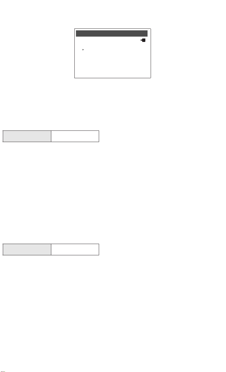
FIGURE 2-2. HART Communicator ScreenWithout Model PX2088 S ma rt De vice Drive r.
Generic
Online
1 Device Setup
2 PV 100.00 inH2O
3 AO 20.00 mA
4 LRV 0.00 inH2O
5 URV 100.00 inH2O
REVIEW CONFIGURATION DATA
Review all of the factory-set configuration data to ensure that is reflects the needs of
your application before operating the transmitter in an actual installation.
Review
HART Fast Keys
Review the transmitter configuration parameters set at the factory to ensure
accuracy and compatibility with your particular application. After activating the
review function, scroll through the data list to check each variable. Refer to “Basic
Setup” in this section of the manual if a change to the transmitter configuration data
is necessary.
1, 5
CHECK OUTPUT
Before performing other transmitter on-line operations, review the digital output
parameters to ensure that the transmitter is operating properly and is configured to
the appropriate process variables.
Process Variables
HART Fast Keys
The process variables for the Model PX2088 Smart provide the transmitter output,
and are continuously updated. The Process Variable menu displays the following
process variables:
nPressure
nPercent Range
nAnalog Output
1, 1
2-3
Page 12

BASIC SETUP
From the Basic Setup menu you can configure the transmitter for certain basic
variables. In many cases, all of these variables are pre-configured at the factory.
Configuration may be required if your transmitter is not configured or if the
configuration variables need revision.
Tag
HART Fast Keys
1, 3, 1
The Tag variable is the easiest way to identify and distinguish between transmitters
in multi-transmitter environments. Use this variable to label transmitters
electronically according to the requirements of your application. The tag you define
is automatically displayed when a HART-based communicator establishes contact
with the transmitter at power-up. The tag may be up to eight characters long and
has no impact on the primary variable readings of the transmitter.
Output Units
HART Fast Keys
The Unit command sets the desired primary variable units. Set the transmitter
output to one of the following engineering units:
ninH
O
2
ninHg
nftH
O
2
nmmH
O
2
npsi
nbar
nmbar
nInH
O @ °4 C
2
NOTE
Output units is the only variable which must be sent separately from all other
variable configurations. After changing units, press SEND (F2) so the
microprocessor will recalculate the associated variables (4–20 mA points, for
example). The Model PX2088 Smart recalculates all variables that depend on units.
After the transmitter recalculates the variables, you may change any of the
remaining parameters.
1, 3, 3
ng/cm
nkg/cm
nPa
nkPa
ntorr
natm
nmmH
2
2
O @ °4 C
2
2-4
Page 13

Rerange
HART Fast Keys
1, 3, 3
The Range Values command sets the 4 and 20 mA points (lower and upper range
values). Setting the range values to the limits of expected readings maximizes
transmitter performance; the transmitter is most accurate when operated within the
expected pressure ranges for your application. In practice, you may reset the
transmitter range values as often as necessary to reflect changing process
conditions.
You may use one of three methods to rerange the transmitter. Each method is
unique; examine all three closely before deciding which method to use.
NOTE
Regardless of the range points, the Model PX2088 Smart will measure and report all
readings within the digital limits of the sensor. For example, if the 4 and 20 mA
points are set to 0 and 10 inH
it digitally outputs the 25 in H
However, there may be up to ±5.0% error associated with output outside of the range
O, and the transmitter detects a pressure of 25 inH2O,
2
O reading and a 250% percent of span reading.
2
points.
Method 1:Rerange Using the Communicator
Reranging using only the communicator is the easiest and most popular way to
rerange the transmitter. This method changes the values of the analog 4 and 20
mA points independently without a pressure input.
To rerange using only the communicator enter the fast-key sequence above, select
1 Keypad input, and follow the on-line instructions. Or enter the values directly
from the HOME screen.
Method 2:Rerange Using the Communicator and a Pressure Source or Process
Pressure
Reranging using the communicator and a pressure source or process pressure is a
way of reranging the transmitter when specific 4 and 20 mA points are not known.
This method changes the values of the analog 4 and 20 mA points. When you set
the 4 mA point the span is maintained; when you set the 20 mA point the span
changes.
To rerange using the communicator and a pressure source or process pressure
enter the fast-key sequence above, select 2 Apply values, and follow the on-line
instructions.
Method 3:Rerange Using the Local Zero and Span Buttons
and a Pressure Source or Process Pressure
Reranging using the local zero and span adjustments and a pressure source is a
way of reranging the transmitter when specific 4 and 20 mA points are not known
or a communicator is not available. When you set the 4 mA point the span is
maintained; when you set the 20 mA point the span changes.
To rerange using the zero and span adjustments, refer to “Rerange Procedure” on
page 4-13.
2-5
Page 14

Damping
HART Fast Keys
The Damping command changes the response time of the transmitter to smooth
variations in output readings caused by rapid changes in input. Determine the
appropriate damping setting based on the necessary response time, signal stability,
and other requirements of the loop dynamics of your system. The default damping
value is 0.50 seconds and can be reset in fixed increments of 0.05, 0.10, 0.20, 0.40,
0.80, 1.60, 3.20, 6.40, 12.8, or 25.6 seconds.
1. 3. 6
DETAILED SETUP
Meter Setup
HART Fast Keys
The Meter Type command allows you to configure the transmitter for use with an
LCD meter. Transmitters shipped without meters are set to “NONE.” Change the
meter settings as often as necessary to reflect changing process or application
conditions. To change the meter settings, and thereby configure the transmitter to
recognize the LCD meter, perform the following procedure.
1.Select 1 Device setup, 4 Detailed setup, 3 Output condition, 4 Meter options to
prepare to change the meter settings.
2.Select the appropriate variable configuration from the Meter options screen,
and press enter.
1, 4, 3, 4
NOTE
Selecting “None” from the meter type screen will disable the meter.
3.Select SEND to download the new meter configuration information to the
transmitter.
For a more detailed description of the LCD meter features and diagnostic messages,
refer to Section 7 LCD Meter.
Burst Mode
HART Fast Keys
Burst Mode sets the transmitter to maintain digital contact with a Digital Control
System that has custom software to support burst mode. When the Model PX2088
Smart is configured for burst mode, it provides faster digital communication from
the transmitter to the control system by eliminating the time required for the control
system to request information from the transmitter.
1, 4, 3, 4, 3
2-6
Page 15

Burst mode is compatible with use of the analog signal. Because HART® protocol
features simultaneous digital and analog data transmission, the analog value can
drive other equipment in the loop while the control system is receiving the digital
information. Burst mode applies only to the transmission of dynamic data (pressure
and temperature in engineering units, pressure in percent of range, and/or analog
output in mA or V), and does not affect the way other transmitter data is accessed.
Access to information other than dynamic transmitter data is obtained through the
normal poll/response method of HART communication. A HART-based
communicator or the control system may request any of the information that is
normally available while the transmitter is in burst mode. Between each message
sent by the transmitter, a short pause allows the HART-based communicator or a
control system to initiate a request. The transmitter will receive the request, process
the response message, and then continue “bursting” the data approximately three
times per second.
Save, Recall, or Clone Configuration Data
HART Fast Keys
Data that was entered off-line can be stored in the communicator memory and
downloaded to other transmitters later. Data also can be copied from a transmitter in
order to be sent to other transmitters in a process known as “cloning”. This is
especially useful if you work with a large number of transmitters that require the
same configuration data.
left arrow, 3 (note)
Enable or Disable Local Span and Zero Buttons
HART Fast Keys
The Local Keys command allows you to enable or disable the local span and zero
buttons. Disabling the local keys will prevent unauthorized reranging using the span
and zero buttons, but will not prevent reranging using the communicator . To prevent
all changes to the configuration data, use the transmitter security jumper (see
“Transmitter Security” on page 4-12).
1, 4, 4, 1, 7
2-7
Page 16

CALIBRATION
Calibrating the transmitter increases the precision of your measurement system.
You may use one or more of a number of trim functions when calibrating.
To understand the trim functions, it is necessary to understand that smart
transmitters operate differently from analog transmitters. An important difference is
that smart transmitters are fa ctory -c haracte rized; they are shipped with a standard
sensor curve stored in the transmitter firmware. In operation, the transmitter uses
this information to produce a process variable output, in engineering units,
dependent on the sensor input. The trim functions allow you to make corrections to
the factory-stored characterization curve by digitally altering the transmitter’s
interpretation of the sensor input.
The trim functions should not be confused with the rerange functions. Although the
rerange command matches a sensor input to a 4–20 mA output—as in conventional
calibration—it does not affect the transmitter’s interpretation of the input.
Calibration Overview
Complete calibration of the Model PX2088 Smart Pressure Transmitter involves one or
more of the following tasks:
Configure the Analog Output Parameters
nSet Process Variable Units (Page 2-3)
nRerange (Page 2-5)
nSet Output Type (Page 2-4)
nSet Damping (Page 2-6)
Calibrate the Sensor
nFull Trim (Page 2-10)
nZero Trim (Page 2-10)
Calibrate the 4–20 mA Output
nDigital to Analog Trim (Page 2-11) or
nScaled Digital to Analog Trim (Page 2-12)
Figure 2-3 illustrates the Model PX2088 Smart transmitter data flow. This data flow
can be summarized in four major steps:
1.A change in pressure is measured by a change in the sensor output (Sensor
Signal).
2.The sensor signal is converted to a digital format that can be understood by
the microprocessor (Analog-to-Digital Signal Conversion).
3.Corrections are performed in the microprocessor to obtain a digital
representation of the process input (Digital PV).
4.The Digital PV is converted to an analog value
(Digital-to-Analog Signal Conversion).
2-8
Page 17
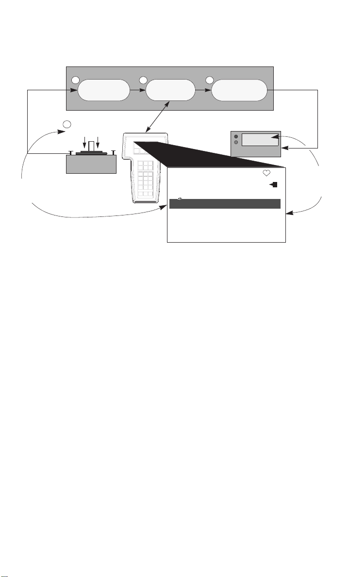
FIGURE 2-3. Transmitter Data Flow
with Calibration Options.
(Transmitter Ranged 0 to 100 inH
2
Transmitter Electronics Module
Analog-to-
Digital Signal
Conversion
3 4
Microprocessor
Digital PV
O)
2
Digital-to-Analog
Signal Conversion
Analog Output
1
100 inH2O
Sensor Signal
Input Device
If readings do not
match perform
sensor trim
NOTES
1)Value on PV line should equal
the input pressure
2)Value on AO line should equal the
output device reading
HART Communications
PX2088S:PT-4763
Online
1 Device Setup
2 PV 100.00 inH2O
3 AO 20.00 mA
4 LRV 0.00 inH2O
5 URV 100.00 inH2O
20.00 mA
Output Device
If readings do
not match
perform
output trim
Deciding Which Trim
Procedure to Use
To decide which trim procedure to use, you must first determine whether the analogto-digital section or the digital-to-analog section of the transmitter electronics is in
need of calibration. To do so, refer to Figure 2-3 and perform the following procedure:
1.Connect a pressure source, a HART communicator, and an output device to
the transmitter.
2.Establish communication between the transmitter and the communicator.
3.Apply the desired 20mA point pressure (100 in H2O, for example).
4.Compare the applied pressure to the Process Variable (PV) line on the
Communicator Online Menu. If the PV reading on the communicator does not
match the applied pressure, and you are certain your test equipment is
accurate, perform a sensor trim.
5.Compare the Analog Output (AO) line on the communicator online menu to
the digital readout device. If the AO reading on the communicator does not
match the digital readout device, and you are certain your test equipment is
accurate, perform an output trim.
Sensor Trim
You can trim the sensor using either the full trim or the zero trim function. The trim
functions vary in complexity, and their use is application-dependent. Both alter the
transmitter’s interpretation of the input signal.
2-9
Page 18

A zero trim is a single-point adjustment. It is useful for compensating for mounting
position effects, and can be performed with the transmitter installed or from the
bench. Since this correction maintains the slope of the characterization curve, it
should not be used in place of a full trim over the full sensor range.
A full trim is a two-point sensor calibration where two end-point pressures are
applied, and all output is linearized between them. Y ou should always adjust the low
trim value first to establish the correct offset. Adjustment of the high trim value
provides a slope correction to the characterization curve based on the low trim value.
The factory-established characterization curve is not changed by this procedure. The
trim values allow you to optimize performance over your specified measuring range
at the calibration temperature.
Zero Trim
HART Fast Keys
1, 2, 3, 3, 1
To calibrate the sensor using the zero trim function, perform the following procedure.
1. Vent the transmitter and attach a communicator to the measurement loop.
2. From the communicator main menu select 1 Device setup,
2 Diagnostics and service, 3 Calibration, 3 Sensor trim, 1 Zero trim to prepare
to adjust the zero trim.
NOTE
The transmitter must be within 3% of true zero (zero based) in order to calibrate
using the zero trim function.
3. Follow the commands provided by the communicator to complete the
adjustment of the zero trim.
Full Trim
HART Fast Keys
1, 2, 3, 3
To calibrate the sensor using the full trim function, perform the following procedure.
1. Assemble and power the entire calibration system including a transmitter,
communicator, power supply, pressure input source, and readout device.
NOTE
Use a pressure input source that is at least three times more accurate than the
transmitter, and allow the input pressure to stabilize for 10 seconds before entering
any values. If remote seals are used allow more time for the input pressure to
stabilize.
2. From the communicator main menu select 1 Device setup,
2 Diagnostics and service, 3 Calibration, 3 Sensor trim, 2 Lower sensor trim to
prepare to adjust the lower trim point.
2-10
Page 19

NOTE
Select pressure input values so that the low and high values are equal to or outside
the 4 and 20 mA points. Do not attempt to obtain reverse output by reversing the
high and low points. The transmitter allows approximately a 5% URL deviation from
the characterized curve established at the factory.
3.Follow the commands provided by the communicator to complete the
adjustment of the lower value.
4.Repeat the procedure for the upper value, replacing 2 Lower sensor trim with
3 Upper sensor trim in Step 2.
Output Trim
The output trim commands allow you to alter the transmitter’s conversion of the
input signal to a 4–20 mA output (see Figure 2-3 on page 2-9). Adjust the analog
output signal at regular intervals to maintain measurement precision. Match the
transmitter output to the output of the digital readout device (ammeter, DCS, etc.).
You can trim the transmitter output using either the digital to analog trim or the
scaled digital to analog trim function.
Digital to Analog Trim
HART Comm.
To perform a digital-to-analog trim, perform the following procedure.
1.From the HOME screen, select 1 Device setup, 2 Diag/Service, 3 Calibration, 4
D/A trim. Select “OK” to after you set the control loop to manual.
2.Connect an accurate reference meter to the transmitter at the “Connect
reference meter” prompt. To do so, connect the meter across the test terminals
in the transmitter terminal compartment, or use the readout device within the
loop.
3.Select “OK” after connecting the reference meter.
4.Select “OK” at the “Setting fld dev output to 4 mA” prompt.
The transmitter outputs 4.00 mA.
5.Record the actual value from the reference meter, and enter it at the “Enter
meter value” prompt.
The communicator prompts you to verify whether or not the output value equals the
value on the reference meter.
6.Select 1 Yes if the reference meter value equals the transmitter output value,
or 2 No if it does not.
If you select 1 Yes, proceed to Step 7.
If you select 2 No, repeat Step 5.
1, 2, 3, 2, 1
1
2-11
Page 20

7.Select “OK” at the “Setting fld dev output to 20 mA” prompt, and repeat Steps
5 and 6 until the reference meter value equals the transmitter output value.
Select “OK” after you return the control loop to automatic control.
Scaled Digital to Analog Trim
HART Comm.
1, 2, 3, 2, 2
The Scaled D/A Trim command matches the 4 and 20 mA points to a user-selectable
reference scale other than 4 and 20 mA (1 to 5 volts if measuring across a 250 ohm
load, or 0 to 100 percent if measuring from a DCS, for example). To perform a scaled
D/A trim, connect an accurate reference meter to the transmitter and trim the
output signal to scale as outlined in the Output Trim procedure.
NOTE
Use a precision resistor for optimum accuracy. If you add a resistor to the loop,
ensure that the power supply is sufficient to power the transmitter to a 20 mA
output with the additional loop resistance.
DIAGNOSTICS AND SERVICE
Test Device
HART Fast Keys
The Test device command initiates a more extensive diagnostic routine than that
performed continuously by the transmitter. If the transmitter test detects a problem,
the communicator displays messages to indicate the source of the problem.
Loop Test
HART Fast Keys
The Loop Test command verifies the output of the transmitter, the integrity of the
loop, and the operations of any recorders or similar devices installed in the loop. To
initiate a loop test, perform the following procedure:
1.From the HOME screen, Select 1 Device Setup, 2 Diagnostics and Service, 2
Loop Test, to prepare to perform a loop test.
2.Select “OK” after you set the control loop to manual.
The communicator displays the loop test menu.
3.Select a discreet milliamp level for the transmitter to output. At the “Choose
analog output” prompt, select 1 4mA, 2 20mA, or select 3 other to manually
input a value between 4 and 20 milliamps.
1, 2, 1, 1
1, 2, 2
2-12
Page 21

4.Check the current meter installed in the test loop to verify that it reads the
value you commanded the transmitter to output. If the readings do not match,
the transmitter requires an output trim or the current meter is
malfunctioning.
After completing the test procedure, the display returns to the loop test screen and
allows you to choose another output value.
MULTIDROP COMMUNICATION
Multidropping transmitters refers to the connection of several transmitters to a
single communications transmission line. Communication between the host and the
transmitters takes place digitally with the analog output of the transmitters
deactivated. Many of the SMART transmitters can be Multidropped.
With the HART smart communications protocol, up to 15 transmitters
can be connected on a single twisted pair of wires or over leased phone lines. Note
that Burst Mode Operation is not compatible with multidrop communications.
The application of a multidrop installation requires consideration of the update rate
necessary from each transmitter, the combination of trans mitter models, and the
length of the transmission line. Multidrop installations are not recommended where
intrinsic safety is a requirement. Communication with the transmitters can be
accomplished with commercially available Bell 202 modems and a host
implementing the HART protocol. Each transmitter is identified by a unique address
(1-15) and responds to the commands defined in the HART protocol.
Figure 2-4 shows a typical multidrop network. This figure is not intended as an
installation diagram.
FIGURE 2-4. Typical Multidrop Network.
Bell 202
RS-232-C
Modem
Power
3051-0087A
HART-based communicators can test, configure, and format a multidropped
transmitter the same way as a transmitter in a standard point-to-point installation.
2-13
Page 22

NOTE
The transmitter is set to address 0 at the factory, allowing it to operate in the
standard point-to-point manner with a 4–20 mA output signal. To activate multidrop
communication, you must change the transmitter address to a number from 1 to 15.
This change deactivates the 4–20 mA analog output, locking it to 4 mA. It also
disables the failure mode alarm signal, which is controlled by the upscale/downscale
jumper position.
Changing a Transmitter Address
HART Fast Keys
1, 4, 3, 4, 1
To change the address of a multidropped transmitter, follow these fast key
sequences. To activate multidrop communication, the transmitter address must be
changed to a number from 1 to 15.
Polling a Multidropped Loop
HART Fast Keys
Left Arrow, 1, 1,
Polling a multidropped loop determines the model, address, and number of
transmitters on the given loop.
NOTE
The Model HC275 HART Communicator requires you to use the Utility Menu to
perform an auto poll. This menu is available from the Main Menu of the HART
Communicator. Press the left arrow to move from the Online Menu to the Main
Menu. Press 4 from the Main Menu to access the Utility Menu. The HART
Communicator will only recognize transmitters with an address of “0” unless polling
is initiated.
2-14
Page 23

SECTION
3 Commissioning the Analog
Transmitter
OVERVIEW
This section contains calibration information for the Models PX2088
Pressure Transmitter. The transmitter can be continuously adjusted to spans
between maximum span and
information is programmed into the microprocessor at the factory; linearity
adjustment is not necessary in the field.
SAFETY MESSAGES
This section contains procedures that require connecting the transmitter, or making
connections in an explosive atmosphere. The following safety messages apply to all
procedures throughout this section requiring cover removal and connection to the
transmitter terminal block. Keep the following safety messages in mind whenever
you perform an operation requiring cover removal or connection to a measurement
loop.
1
/10 of maximum span.Transmitter linearity
Failure to follow safe commissioning guidelines can cause death or serious injury. Please
review the following safety messages before commissioning a Model PX2088
Pressure Transmitter.
■To avoid explosions, do not remove the instrument cover or make electrical connections in
explosive atmospheres when the circuit is alive. Make sure the instrument is installed in
accordance with intrinsically safe or nonincendive field wiring practice.
■To meet explosion proof requirements, make sure that both transmitter covers are fully
engaged.
High voltage that may be present on leads could cause electrical shock:
nAvoid contact with leads and terminals.
1
3-1
Page 24

COMMISSION: ON THE BENCH OR IN THE LOOP
Commission the Model PX2088 Analog transmitter before or after
installation. It may be useful to commission the transmitter on the bench before
installation to ensure proper operation and to avoid exposing the transmitter
electronics to the plant environment. Commissioning consists of applying pressure
and setting the zero and span to the desired values.
FIGURE 3-1. Transmitter Wiring.
TEST TERMINALS
Do not contact meter leads from
either test terminal on the output board to case ground. This can result in the maximum
current from the power supply flowing through the test meter and may blow the test meter
fuse, or damage the test meter or transmitter.
Terminals for connecting an ammeter to the transmitter are provided in both the
terminal and the electronics compartments. To connect an ammeter in the terminal
compartment, connect the positive lead to the terminal marked “+TEST,” and the
negative lead to the terminal marked “–”. To connect an ammeter in the electronics
compartment, attach the positive lead to the terminal marked “+ TEST,” and the
negative lead to the terminal marked “– TEST” (see Figure 3-2).
3-2
Page 25

FIGURE 3-2. Transmitter Terminal and Electronics Compartments.
ELECTRONICS
COMPARTMENT
Potentiometer
Negative Terminal
Test Terminal
TERMINAL
COMPARTMENT
Test
Terminals
Selector
Switch
ZERO AND SPAN ADJUSTMENTS
Adjustment controls for zero and span are located in the transmitter electronics
compartment. Calibrate the transmitter with the three-position switch and the
¾-turn potentiometer (see Figure 3-2).
2088-2088B02H, 2088A02A
Selector Switch
The selector switch is labeled “Z” (Zero), “RUN,” and “S” (Span). The switch is set to
the “RUN” position at the factory, and should remain there under normal operation.
The selector switch must be returned to the “RUN” position after setting the proper
calibration. Failure to return the switch to the “RUN” position will, after 20 minutes, cause
the transmitter to return to the previously set 4–20 mA points. This will result in erroneous
transmitter output.
3-3
Page 26

Potentiometer Adjustment
The procedure for calibrating the Model PX2088 is different from that of any
other pressure transmitters and takes some time to become accustomed to.
However, this method of calibration is considerably faster than other calibration
methods. In addition, there is no interaction between the zero and span adjustments.
An important feature of this design is that the potentiometer is an active part of the
circuit only during calibration. The potentiometer is removed from the active circuit
when the switch is placed in the “RUN” position. This unique design eliminates the
temperature drift and stability shifts often associated with common potentiometers.
The potentiometer is marked “DN” (Down), “FINE,” and “UP.” The coarse
adjustment regions are at each end, and a fine adjustment region is in the center.
The output of the transmitter increases or decreases automatically when the
potentiometer is placed in the coarse adjustment regions. The longer the
potentiometer is held in the coarse adjustment region, the faster the rate of change
in output.
The potentiometer is a ¾-turn device and has a mechanical stop to prevent full rotation. Do
not exert large twisting forces against the mechanical stop or damage will result.
NOTE
When the transmitter output is saturated below 4mA or above 20 mA, the
potentiometer may appear to have no effect on the transmitter calibration because
the microprocessor is adjusting the calibration, but the current-limiting circuitry is
maintaining the output at the saturation levels. Place the potentiometer in the
coarse-adjust region and wait at least 15 seconds for the output to change.
Setting the Zero
Setting the zero point of the transmitter involves applying pressure and adjusting
the potentiometer accordingly. To set the zero point of the transmitter, use the
following procedure:
1.If the transmitter does not have a readout device, attach an ammeter using
the test terminals in either compartment (see Figure 3-2 on Page 3-3).
2.Ensure that the selector switch is in the “RUN” position. Apply the pressure to
which the zero point will be calibrated.
3.Set the selector switch to “Z.”
4.Using the potentiometer, adjust the transmitter output until the readout
device reads the 4 mA.
5.Return the selector switch to the “RUN” position.
3-4
Page 27

The selector switch should not be set to the “Z” position unless the potentiometer will be
adjusted. Failure to adjust the potentiometer while in the “Z” position will result in erroneous
transmitter output during an overpressure event, and a shift in calibration after the
overpressure event. The transmitter can be returned to normal operation by performing
either of the following procedures:
1.Remove power from the transmitter while the selector switch is in the “RUN” position,
and re-apply power. This will reset the former zero calibration.
OR
2.Calibrate the zero point of the transmitter by following the instructions in the section
entitled “Setting the Zero.”
Setting the Span
Setting the span of the transmitter involves applying pressure and adjusting the
potentiometer accordingly. To set the span of the transmitter, use the following
procedure:
1. If the transmitter does not have a readout device, attach an ammeter using
the test terminals in either compartment (see Figure 3-2 on Page 3-3).
2. Ensure that the selector switch is in the “RUN” position. Expose the
transmitter to full scale pressure.
3. Set the selector switch to “S.”
4. Using the potentiometer, adjust the transmitter output until the readout
device reads the 20mA.
5. Return the switch to “RUN.”
3-5
Page 28

3-6
Page 29

SECTION
4
Installation
OVERVIEW
This section contains a flowchart (Figure 4-1 on Page 4-2), installation procedures,
and a wiring diagram (Figure 4-8 on Page 4-10), to guide you to a successful Model
PX2088 installation. Shielded cable should be used for best results in
electrically noisy environments.
Safety Messages
Instructions and procedures in this section may require special precautions to
ensure the safety of the personnel performing the operations. Please read all
warnings before proceding.
nExplosions could result in death or serious injury:
nDo not remove the transmitter cover in explosive atmospheres
when the circuit is alive.
nBefore connecting a HART-based communicator in an explosive atmosphere, make
sure the instruments in the loop are installed in accordance with intrinsically safe or
non-incendive field wiring practices.
nVerify that the operating atmosphere of the transmitter is consistent with the
appropriate hazardous locations certifications.
nBoth transmitter covers must be fully engaged to meet explosion-proof requirements.To
avoid output shifts in critical applications, do not plug the low side with a solid plug.
nTo avoid process leaks, install and tighten all four flange bolts before applying
pressure, or process leakage may result. When properly installed, the flange bolts will
protrude through the top of the module housing. Attempting to remove the flange bolts
while the transmitter is in service may cause process fluid leaks.
Failure to follow these installation guidelines could result in death or serious injury:
nMake sure only qualified personnel perform the installation.
4-1
Page 30

High voltage that may be present on leads could cause electrical shock:
• Avoid contact with leads and terminals.
FIGURE 4-1. Installation Flowchart.
START HERE
VERIFY
A
Apply Pressure
Within
Specifications?
No
Refer to
Troubleshooting
Section
Yes
B
Check Configuration
(See Chapter 2)
Within
Specifications?
No
Set Units
(See Chapter 2)
Set Range Points
Set Output Type
Set Damping
Perform Sensor
and/or Output
Trim
A
Smart
Yes
A
Bench
Calibration?
Yes
Check Configuration
Specifications?
No
ADJUST ANALOG
ZERO/SPAN
(See Chapter 3)
Repeat Steps
until
Calibrated
A
No
Analog
(See Chapter 3)
Within
Yes
FIELD
B
INSTALL
Check Jumper
or Switches
(Smart Only)
Mount
Transmitter
Check for Leaks
(Process
Smart
Zero Trim
Connections)
Wire
Transmitter
Power
Transmitter
Analog
Zero
Transmitter
A
Confirm Transmitter
Configuration
Transmitter for
Mounting Effects
4-2
DONE
Page 31

INSTALLATION
Installation consists of attaching the transmitter to the process piping and making
electrical connections.
The Model PX2088 weighs approximately 2.0 pounds (0.9 kg). In many cases, its
compact size and light weight makes it possible to mount the Model PX2088 directly to
the impulse line without using an additional mounting bracket. When this is not
desirable, mount directly to a wall, panel, or two-inch pipe using the optional
mounting bracket (see Figure 4-3).
INSTALLATION PROCEDURES
Model PX2088
Do not apply torque directly to the electronics housing. Rotation between the electronics
housing and the process connection can damage the electronics. To avoid damage, apply
torque only to the hex-shaped process connection.
Electronics
Housing
Process
Connection
Impulse Piping
Impulse piping configurations depend on specific measurement conditions. Use the
following information and Figure 4-2 as a guideline when installing impulse piping.
Liquids: Make the line tap on the side of the pipe to prevent sediment deposits
from plugging the impulse line or transmitter. Mount the transmitter level with or
below the tap so gases vent into the process line.
Gases: Make the line tap on either the top or the side of the process line. Mount the
transmitter level with or above the line tap so liquids drain into the process line.
Steam: Make the line tap in the side of the process line. Mount the transmitter
below the line tap to ensure that the impulse line remains filled with condensate.
4-3
Page 32

FIGURE 4-2. Model PX2088 Mounting Configurations for Liquids, G ases, an d Ste am .
GAS OR LIQUID
SERVICE
LIQUID OR STEAM
SERVICE
GAS
SERVICE
FIGURE 4-3. Model PX2088 Mounting Configurations with Optional Bracket.
5.2
(132)
3.6
(91)
1.25
(32)
2.48
(63)
Hex
5.97
(152)
Mounting bracket ordering
code MB,
and optional block and bleed
valve.
3.10
(79)
2-inch U-Bolt
for Pipe
Mounting
NOTE
Dimensions are in
inches
(millimeters).
4-4
Page 33

nExplosions could result in death or serious injury:
nDo not remove the transmitter cover in explosive atmospheres
when the circuit is alive.
nBefore connecting a HART-based communicator in an explosive atmosphere, make
sure the instruments in the loop are installed in accordance with intrinsically safe or
non-incendive field wiring practices.
nVerify that the operating atmosphere of the transmitter is consistent with the
appropriate hazardous locations certifications.
nBoth transmitter covers must be fully engaged to meet explosion-proof requirements.To
avoid output shifts in critical applications, do not plug the low side with a solid plug.
High voltage that may be present on leads could cause electrical shock:
•Avoid contact with leads and terminals.
To power the transmitter, connect the positive power lead to the terminal marked
“SIG +” and the negative power lead to the terminal marked “–” (see Figure 4-8 on
Page 4-10). Tighten the terminal screws to ensure that adequate contact is made. No
additional power wiring is required.
To connect test equipment for monitoring the output of the Model PX2088
during maintenance procedures, connect one lead to the terminal labeled
“TEST+” and the other lead to the terminal labeled “–” (see Figure 4-8 on Page 4-10).
Avoid contact with the leads and the terminals.
Signal wiring may be grounded at any one point on the measurement loop, or it may
be left ungrounded. The negative side of the power supply is a recommended
grounding point. The transmitter case may be grounded or left ungrounded.
Conduit connections at the transmitter should be sealed to prevent moisture
accumulating in the field terminal side of the transmitter housing. Also, install
wiring with a drip loop with the bottom of the drip loop lower than the conduit
connection of the transmitter housing.
4-9
Page 34

FIGURE 4-8. Transmitter Field Wiring.
Ground Terminal
Power
Supply
Positive Terminal
Negative Terminal
Test Terminal
Signal loop may be grounded at
any point or left ungrounded
Power Supply
The dc power supply should provide power to the transmitter with less than one
percent ripple. The total loop resistance load is the sum of the resistance of the signal
wires and the resistance load of the controller, indicator, and other pieces of
equipment in the loop. Note that the resistance of intrinsic safety barriers, if used,
must be included. Figure 4-9 shows the transmitter power supply load limitations.
FIGURE 4-9. Transmitter Load Limitations.
MODEL PX2088
Max. Load = 45.4 (Power Supply Voltage) –10.5
Operating
Load (Ohms)
Power Supply (dc Volts)
(1)For CENELEC EX ia approval, power supply
must not exceed 30 volts.
NOTE
Minimum load impedance for Output Code M
is 100 kilohms.
Region
(1)
4-10
Page 35

FAILURE MODE AND SECURITY JUMPERS
(Security Jumpers are Available with Smart Transmitters Only)
Failure Mode
As part of normal operation, the Model PX2088 Smart continuously monitors its
own operation. This automatic diagnostic routine is a timed series of checks repeated
continuously. If the diagnostic routine detects a failure in the transmitter, the
transmitter drives its output either below or above specific values depending on the
position of the failure mode jumper or switch.
Smart Transmitters
Whether the output is driven high or low when in failure mode is user-selectable by a
jumper on the transmitter. The values to which 4–20 mA transmitters drive their
output in failure mode depend on whether they are factory-configured to standard or
NAMUR-compliant operation. The values for each are as follows:
Standard Operation
linear output:3.9 ≤ I ≤ 20.8 mA
fail low: 3.75 mA
fail high 21.75 mA
NAMUR-Compliant Operation (Option Code C4)
linear output:3.8 ≤ I ≤ 20.8 mA
fail low: 3.6 mA
fail high: 22.5
To determine the failure mode configuration of your transmitter, review the failure
mode options using a Model HC275 HART Communicator.
NOTE
The failure mode configuration, whether standard or NAMUR-compliant, is
configured at the factory and can not be changed in the field.
Failure Mode Jumper Locations
Without a meter installed
The failure mode alarm jumper is located on the front side of the electronics
module just inside the electronics housing cover and is labeled ALARM (See
Figure 4-10). Do not remove the instrument cover in explosive atmospheres when
the circuit is alive. Both transmitter covers must be fully engaged to meet
explosion proof requirements.
With a meter installed
The failure mode alarm jumper is located on the LCD faceplate in the electronics
module side of the transmitter housing and is labeled ALARM (See Figure 4-10).
Do not remove the instrument cover in explosive atmospheres when the circuit is
alive. Both transmitter covers must be fully engaged to meet explosion proof
requirements.
Analog Transmitters
If self diagnostics detect a sensor or microprocessor failure, the analog signal is
driven low to alert the user (I ≤ 3.6 mA or V≤ 1V for output Code M).
4-11
Page 36

Transmitter Security
(Security Jumpers are Available with Smart Transmitters Only)
After commissioning the transmitter, you may wish to protect the configuration data
from unwarranted changes. The transmitter is equipped with a security jumper that
can be positioned to prevent changes to the configuration data. (see Figure 4-10).
Remember that the circuit board is electrostatically sensitive. Be sure to observe
handling precautions for static-sensitive components to avoid damage to the circuit
board.
When the transmitter security jumper is in the “ON” position, the transmitter will
not accept any “writes” to its memory. This means that configuration changes (such
as digital trim and reranging) cannot take place when the transmitter security is on.
The zero and span adjustment buttons are also disabled. To reposition the jumper,
use the following procedure.
1.If the transmitter is installed, secure the loop, and remove power.
2.Remove the housing cover opposite the field terminal side. Do not remove the
instrument cover in explosive atmospheres when the circuit is alive.
3.Reposition the jumper. Avoid contact with the leads and the terminals. Refer
to Figure 4-10 for the location of the jumper and the ON and OFF positions.
4.Reattach the transmitter cover. The cover must be fully engaged to comply
with explosion-proof requirements.
FIGURE 4-10. Transmitter Alarm and Security Jumper Locations.
Alarm and Security Jumpers Without Meter
Alarm
Security
Alarm and Security Jumpers With Meter
Alarm
y
Securit
NOTE
If either the alarm or security jumper is dislodged or removed from its position the
transmitter reverts to default alarm or security settings of:
Alarm: output high
Security: off
ZERO AND SPAN ADJUSTMENTS
Smart
The Model PX2088 Smart is equipped with local zero and span adjustment buttons. The
buttons are located on the top of the transmitter beneath the certifications label. Use
the zero and span adjustments to set the 4 and 20 mA output points.
4-12
Page 37

Rerange Procedure
To rerange the transmitter using the span and zero buttons, perform the following
procedure.
1. Loosen the screw holding the nameplate on top of the transmitter housing and
rotate the nameplate to expose the zero and span buttons (see Figure 4-11).
2. Using a pressure source with an accuracy three to ten times the desired
calibrated accuracy, apply a pressure equivalent to the lower range value.
3. To set the 4 mA point, press and hold the zero button for at least two seconds,
then verify that the output is 4 mA. If a meter is installed, it will display
ZERO PASS.
4. Apply a pressure equivalent to the upper range value.
5. To set the 20 mA point, press and hold the span button for at least two seconds,
then verif y t h at th e ou t pu t i s 2 0 mA . If a meter is installed, it will display
SPAN PASS.
NOTE
If the transmitter security jumper is in the “ON” position, or if the local zero and
span adjustments are disabled through the software, you will not be able to make
adjustments to the zero and span using the local buttons. Refer to Figure 4-10 on
Page 4-12 for the proper placement of the transmitter security jumper.
FIGURE 4-11. Local Zero and Span Adjustments.
Span and Zero Adjustment Buttons
Disabling the Zero and Span Adjustments
After you rerange the transmitter using the span and zero adjustments, you may
wish to disable the adjustments to prevent further reranging. To disable the span
and zero adjustments, either activate the transmitter security jumper (see
“Transmitter Security” on Page 4-12) or use the sofware to disable the zero and span
adjustment buttons (HART fast key sequence 1,4,4,1,7).
NOTE
The transmitter security jumper prevents any changes to the transmitter
configuration data. The software lockout sequence only disables the local span and
zero adjustment buttons.
4-13
Page 38

Analog
If it is necessary to make zero or span adjustments after installation of the
transmitter, use the zero/span selector switch and the potentiometers to rerange the
transmitter
4-14
Page 39

SECTION
5
Troubleshooting
This section provides basic troubleshooting suggestions to help solve the most
common operating problems.
The following performance limitations may inhibit efficient or safe operation. Critical
applications should have appropriate diagnostic and backup systems in place.
Pressure transmitters contain an internal fill fluid. It is used to transmit the process pressure
through the isolating diaphragms to the pressure sensi ng ele ment. In rare cases, oil leak
paths in oil-filled pressure transmitters can be created. Possible causes include: physical
damage to the isolator diaphragms, process fluid freezing, isolator corrosion due to an
incompatible process fluid, etc.
A transmitter with an oil fill fluid leak can continue to perform normally for a period of time.
Sustained oil loss will eventually cause one or more of the operating parameters to exceed
published specifications while a small drift in operating point output continues. Symptoms of
advanced oil loss and other unrelated problems include:
nSustained drift rate in true zero and span or operating point output or both.
nSluggish response to increasing or decreasing pressure or both.
nLimited output rate or very nonlinear output or both.
nChange in output process noise.
nNoticeable drift in operating point output.
nAbrupt increase in drift rate of true zero or span
or both.
nUnstable output.
nOutput saturated high or low.
FIGURE 5-1. Range of Output.
3.9
mA
3.6 for Analog
3.75 for Smart
Fail Low
(1) Failure mode for output code M is
≤1V.
(2) Above Values are for Standard
Failure Mode. NAMUR compliant
values are different than above.
4
(1)
Process Variable
Out of Range
Normal Operating Range
Hardware Alarm
5-1
20
20.8
21.75
Fail High
Smart only
Page 40

TROUBLESHOOTING
TABLE 5-1. Smart Transmitter Troubleshooting and Corrective Actions.
Symptom Potential Source Corrective Action
High Output Impulse Piping, •Check for blockage in the impulse line.
Electronics •Check test equipment.
Power Supply •Check the output voltage of the power supply at the
Other Components •Replace the transmitter.
Erratic Output Impulse Piping •Check for leaks or blockage in the impulse line.
Loop Wiring •Check for adequate voltage to the transmitter.
Electronics •Check for EMF interference.
Other Components •Replace the transmitter.
•Check to ensure that the blocking valve is fully open.
•Check for trapped gas in a liquid line, or trapped liquid
in a gas line.
•Check to ensure that the density of the fluid in the
impulse line is unchanged.
•Check for sediment in the transmitter process
connection. If you find sediment, flush the process
connection clean with water or an appropriate solvent.
Do not attempt to scrape sediment free; doing so
could puncture the thin isolating diaphragm and destroy
the transmitter.
•Check for frozen process fluid in the process connector.
•Perform full sensor trim.
transmitter.
•Check to ensure that the blocking valve is fully open.
•Check for trapped gas in a liquid line, or trapped liquid
in a gas line.
•Check to ensure that the density of the fluid in the
impulse line is unchanged.
•Check for sediment in the transmitter process
connection. If you find sediment, flush the process
connection clean with water or an appropriate solvent.
•Check for frozen process fluid in the process connector.
•Check for trapped gas in a liquid line, or trapped liquid
in a gas line.
•Check for intermittent shorts, open circuits, and multiple
grounds.
•Check damping.
•Replace the output board and recalibrate the
transmitter.
(1)
(1)
5-2
Page 41

TABLE 5-1. (continued).Smart Transmitter Troubleshoot ing and Co rrective Actions.
Symptom Potential Source Corrective Action
Low Output or
No Output
Impulse Piping •Check for leaks or blockage in the impulse line.
•Check to ensure that the blocking valve is fully open.
•Check for trapped gas in a liquid line, or trapped liquid
in a gas line.
•Check to ensure that the density of the fluid in the
impulse line is unchanged.
•Check for sediment in the transmitter process
connection. If you find sediment, flush the process
connection clean with water or an appropriate solvent.
Do not attempt to scrape sediment free; doing so
could puncture the thin isolating diaphragm and destroy
the transmitter.
•Check for frozen process fluid in the process connector.
Loop Wiring •Check test equipment.
•Check for adequate voltage to the transmitter.
•Check the current rating of the power supply against the
total current being drawn by all transmitters being
powered.
•Check for intermittent shorts, open circuits, and multiple
grounds.
•Check for proper polarity at the signal terminals.
•Check the loop impedance.
Electronics •Replace the electronics board and recalibrate the
transmitter.
Other Components •Replace the transmitter.
TABLE 5-2. Analog Transmitter Troubleshooting Symptoms and Corrective Actions.
Symptom Potential Source Corrective Action
High Output Impulse Piping •Check for blockage in the impulse line..
Power Supply •Check the output voltage of the power supply at the
Output Electronics •Replace the output board and recalibrate the transmitter.
Other Components •Replace the transmitter.
•Check to ensure that the blocking valve is fully open.
•Check for trapped gas in a liquid line, or trapped liquid in
a gas line.
•Check to ensure that the density of the fluid in the
impulse line is unchanged.
•Check for sediment in the transmitter process
connection. If you find sediment, flush the process
connection clean with water or an appropriate solvent.
Do not attempt to scrape sediment free; doing so
could puncture the thin isolating diaphragm and destroy
the transmitter.
•Check for frozen process fluid in the process connector.
transmitter.
(1)
5-3
Page 42

TABLE 5-2. (continued).Analog Transmitter Troubleshooting and Co rrect ive Acti ons.
Symptom Potential Source Corrective Action
Erratic Output Impulse Piping •Check for leaks or blockage in the impulse line.
Loop Wiring •Check for adequate voltage to the transmitter.
Output Electronics •Replace the output board and recalibrate the transmitter.
Other Components •Replace the transmitter.
Low Output or
No Output
Impulse Piping •Check for leaks or blockage in the impulse line.
Loop Wiring •Check for adequate voltage to the transmitter.
Output Electronics •Replace the output board and recalibrate the transmitter.
Other Components •Replace the transmitter.
•Check to ensure that the blocking valve is fully open.
•Check for trapped gas in a liquid line, or trapped liquid in
a gas line.
•Check to ensure that the density of the fluid in the
impulse line is unchanged.
•Check for sediment in the transmitter process
connection. If you find sediment, flush the process
connection clean with water or an appropriate solvent.
•Check for frozen process fluid in the process connector.
•Check for trapped gas in a liquid line, or trapped liquid in
a gas line.
•Check for intermittent shorts, open circuits, and multiple
grounds.
•Check to ensure that the blocking valve is fully open.
•Check for trapped gas in a liquid line, or trapped liquid in
a gas line.
•Check to ensure that the density of the fluid in the
impulse line is unchanged.
•Check for sediment in the transmitter process
connection. If you find sediment, flush the process
connection clean with water or an appropriate solvent.
Do not attempt to scrape sediment free; doing so
could puncture the thin isolating diaphragm and destroy
the transmitter.
•Check for frozen process fluid in the process connector.
•Check the current rating of the power supply against the
total current being drawn by all transmitters being
powered.
•Check for intermittent shorts, open circuits, and multiple
grounds.
•Check for proper polarity at the signal terminals.
•Check the loop impedance.
5-4
Page 43

SECTION
6 Spare Parts and Ordering
SPARE PARTS
.
FIGURE 6-1. Model PX2088 Smart Transmitter Exploded View.
1
5
LCD Meter Cover Assembly
includes LCD Cover and Oring
6
8
2
1
Part Description Item No. Part Number Spares Category
Smart Transmitters (Output Code S)
Electronics Cover (with O-ring)
LCD Meter Cover Assembly
Cover O-rings
Electronics Board Kits
S Output (4–20 mA/Digital HART
Protocol)
S Output (NAMUR Compliant
Operation)
Optional Mounting Bracket
(with 2-inch U-Bolt for Pipe
Mounting)
LCD Meter Kit with Cover
LCD Meter Kit without Cover
Local Zero and Span Kit
Standard Terminal Block
Transient Protection BLock
7
1, 2
6
2
3
3
4
5, 6
5
7
8
8
2
03031-0292-0001
03031-0193-0002
03031-0232-0001
02088-0306-0002
02088-0306-0003
02088-0071-0001
03031-0193-0101
03031-0193-0103
3031-0293-0002
3031-0332-0003
3031-0332-0004
3
4
(1)
B
B
A
A
A
A
B
B
(1) One spare part is recommended for every 25 transmitters in category A, and one spare part for
every 50 transmitters in category B.
6-1
Page 44

FIGURE 6-2. Replacement Parts for the Model PX2088.
1
2
4
2088-2088A04B
5
6
LCD Meter Cover Assembly
includes LCD Cover and O-ring
3
2
2090-2088D03A
1
2088-2088A03B
Part Description Item No. Part Number Spares Category
(1)
Analog Transmitters
(Output Codes A and M)
Electronics Cover
LCD Meter Cover Assembly
Cover O-rings
Electronics Board Kits
(2)
A Output (4–20 mA)
M Output (1–5 V)
1
6
2
3
3
02088-0014-0002
02088-0075-0003
02088-0073-0001
02088-0076-0001
02088-0077-0001
B
B
A
A
Transient Protection
A Output (4–20 mA)
M Output (1–5 V)
--
--
02088-0214-0001
02088-0216-0001
A
A
Optional Mounting Bracket
(with 2-inch U-Bolt for Pipe
Mounting)
LCD Meter Kit with Cover
(3)
LCD Meter Kit without Cover
(3)
4
5, 6
5
02088-0071-0001
02088-0075-0001
02088-0075-0002
A
(1) One spare part is recommended for every 25 transmitters in category A, and one spare part for
every 50 transmitters in category B.
(2) Assembly hardware is included.
(3) Engineering Unit Label Provided.
6-2
Page 45

Page 46

SECTION
7 LCD Meter
LCD METER FOR SMART TRANSMITTERS
The LCD meter provides local indication of the output, and abbreviated diagnostic
messages governing transmitter operation. The meter is located on the electronics
module side of the transmitter, maintaining direct access to the signal terminals. An
extended cover is required to accommodate the LCD Meter for Smart Transmitters.
The LCD Meter can be ordered with the transmitter or added at a later time.
The new meter features a two-line display that accommodates five digits for
reporting the process variable on the top line, and six characters for displaying
engineering units on the bottom line. The meter uses both lines to display
diagnostic messages. You can configure the meter to display the following
information:
nEngineering Units
nPercent of Range
nUser-Configurable LCD Scale
nAlternating between any two of the above
The user-configurable scale is a new feature that enables you to configure the LCD
meter to a custom scale using a Model HC275 HART Communicator. With the user
configurable scale feature, you can define the decimal point position, the upper range
value, the lower range value, the engineering units, and the transfer function.
Use a HART-based communicator to change the engineering units displayed by the
meter. Select from the following engineering units:
Engineering Unit LCD Readout Engineering Unit LCD Readout
inH2O @20DegC INH2O g/Sqcm G/CM2
mmH2O @20DegC MMH20 kg/Sqcm KG/CM2
ft H2O FTH2O Pa PA
inHg INHG kPa KPA
mmHg MMHG torr TORR
psi PSI atm ATM
bar BAR inH2O @4DegC INH2O
mbar MBAR mmH2O @4DegC MMH2O
Note the following LCD temperature limits:
Operating: –4 to 175 °F (–20 to 80 °C)
Storage: –40 to 185 °F (–40 to 85 °C)
7-1
Page 47

FIGURE 7-1. Exploded View of the Transmitter with Optional LCD Meter.
Interconnecting Pins
Jumpers (top and bottom)
LCD Meter
Extended Cover
Diagnostic Messages
In addition to the output, the LCD meter displays abbreviated operation, error, and
warning messages for troubleshooting the transmitter. Messages appear according to
their priority, with normal operating messages appearing last. To determine the
cause of a message, use a Model HC275 HART Communicator to further interrogate the
transmitter. A description of each LCD diagnostic message follows.
Error
Error messages appear on the LCD meter display to inform you of serious problems
effecting the operation of the transmitter. The meter displays an error message until
the error condition is corrected, and the analog output is driven to the specified
alarm level. No other transmitter information is displayed during an alarm
condition.
FAIL
The transmitter CPU board and the sensor module are incompatible.
FAIL MODULE
The sensor module is disconnected or is malfunctioning. Verify that the sensor
module ribbon cable is connected to the back of the electronics board. If the ribbon
cable is not disconnected, there is a problem within the sensor module. Possible
sources of problems include:
nPressure or temperature updates are not being received in the sensor module
nA non-volatile memory fault that will effect transmitter operation has been
detected in the module by the memory verification routine–this condition is
not repairable, the transmitter must be replaced
FAIL ELECT
The transmitter electronics module is malfunctioning. Possible causes include:
nInternal fault
nA non-volatile memory fault that will effect transmitter operation has been
detected in the module by the memory verification routine
Neither problem is user-repairable; you must replace the electronics board.
2088S-2088A05B
7-2
Page 48

FAIL CONFIG
A non-volatile memory fault has been detected in the transmitter memory by the
memory verification routine. The memory fault is in a location that could effect
transmitter operation, and is user-accessible. To correct this problem, use a Model
HC275 HART Communicator to interrogate and reconfigure the appropriate portion
of the transmitter memory.
Warnings
Warnings appear on the LCD meter display to alert you of user-repairable problems
with the transmitter, or current transmitter operations. Warnings appear
alternately with other transmitter information until the warning condition is
corrected or the transmitter completes the operation that warrants the warning
message.
PRESS LIMIT
The process variable read by the transmitter is outside of sensor range limits.
CURR FIXED
The transmitter is in multidrop mode. The analog output is not tracking pressure
changes.
CURR SATURD
The pressure read by the module is outside of the specified range, and the analog
output has been driven to saturation levels ( “Failure Mode” on Page 4-11).
LOOP TEST
A loop test is in progress. During a loop test or 4–20 mA trim, the analog output is
set to a fixed value. The meter display alternates between the current selected in
milliamps and “LOOP TEST.”
XMTR INFO
A non-volatile memory fault has been detected in the transmitter memory by the
memory verification routine. The memory fault is in a location containing
transmitter information. To correct this problem, use a Model HC275 HART
Communicator to interrogate and reconfigure the appropriate portion of the
transmitter memory. This warning does not effect the transmitter operation.
Operation
Normal operation messages appear on the LCD meter to confirm actions or inform
you of transmitter status. Operation messages are displayed with other transmitter
information, and warrant no action to correct or alter the transmitter settings.
ZERO PASS
The zero value, set with the local zero adjustment button, has been accepted by the
transmitter, and the output should change to 4 mA.
ZERO FAIL
The zero value, set with the local zero adjustment button, exceeds the maximum
rangedown allowed for a particular range, or the pressure sensed by the transmitter
exceeds the sensor limits.
7-3
Page 49

SPAN PASS
The span value, set with the local span adjustment button, has been accepted by the
transmitter, and the output should change to 20 mA.
SPAN FAIL
The span value, set with the local span adjustment button, exceeds the maximum
rangedown allowed for a particular range, or the pressure sensed by the transmitter
exceeds the sensor limits.
LOCAL DSBLD
This message appears during reranging with the integral zero and span buttons and
indicates that the transmitter local zero and span adjustments have been disabled.
The adjustments may have been disabled by the transmitter security jumper on the
transmitter circuit board or through software commands from the Model HC275 refer
to “Failure Mode and Security Jumpers” on Page 4-11 for information on the position
of the security jumper, and for information on the software lockout.
WRITE PROTCT
The write protect (SECURITY) jumper is set to disable changes to the transmitter
configuration data. Refer to “Failure Mode and Security Jumpers” on page 4-11 for
more information on the security jumper.
LCD METER FOR ANALOG TRANSMITTERS
The LCD meter displays a digital value that is proportional to the pressure
measured by the transmitter. The zero point of the indicator may be set to any value
between –999 and 1000. The full scale point may be set to any value between 1.000
and 9999. In addition, adhesive labels are provided with the LCD meter option so
that you can scale the indication to display in engineering units of pressure or level
(see Figure 7-2).
Note the following LCD temperature limits:
Operating:–4 to 175 °F (–20 to 80 °C).
Storage: –40 to 185 °F (–40 to 85 °C).
FIGURE 7-2. LCD Meter
on a Model PX2088 Analog.
Meter Selector
Transmitter Selector
Switch
Switch
Engineering Units
LCD
Potentiometer Adjustment
7-4
Page 50

DIAGNOSTIC MESSAGE DISPLAY
Model PX2088 Analog Transmitter conducts regular diagnostic
routines and can identify several types of failure conditions. If the transmitter
detects a failure, the indicator displays “FAIL”. In addition to detecting and
displaying transmitter failures, the meter display will flash when other conditions
exist. When the transmitter is under-ranged or –999 is exceeded, the display will
flash “–999.” When the transmitter output is saturated or 9999 is exceeded, the
display will flash “9999.”
INSTALLATION
Installing the LCD meter to the transmitter involves removing the plastic cover and
the captive screws from the output board, and attaching the local indicator.
Explosions can result in death or serious injury. Do not remove the instrument cover in
explosive environments while power is supplied to transmitter.
Disconnect power to the transmitter before removing the output board. Failure to follow this
procedure could result in permanent damage to the transmitter electronics.
The circuit board is electrostatically sensitive. To prevent damage to the circuit board, be
sure to observe handling precautions for static-sensitive components.
To install an LCD meter, perform the following procedure: Remove the cover from the
electronics side of the transmitter.
1.Loosen the two captive screws holding the output board and plastic cover in
place.
2.Remove the plastic cover and the two captive screws from the output board.
7-5
Page 51

NOTE
If you are using a transmitter that has a white plastic electronics cover, perform the
following procedure to replace it with a local indicator. If you are using a transmitter
that has a black plastic electronics cover, proceed to Step 4
.
a. Gently remove the output board from the microprocessor board.
b. Completely remove the two captive screws from the white plastic
cover and the output board. Carefully remove the plastic cover
from the output board.
c. Carefully reattach the output board to the microprocessor board,
taking care to correctly align the screw holes and all
interconnecting pins.
Continue with Steps 4 through 6 to complete the installation.
3. Attach the local indicator to the output board, taking care to correctly align
the selector switch and potentiometer with the appropriate holes on the local
indicator. Also, make certain the interconnecting pins near the top of the
output board mesh correctly with the rear of the local indicator.
4. Tighten the two captive screws and install the LCD meter cover.
CONFIGURATION
Before configuring the indicator, make sure the transmitter output is set to the
desired calibration.
NOTE
The local indicator option does not allow access to the test terminals on the output
circuit board. To measure the transmitter output during calibration, connect an
ammeter to the test terminals in the terminal compartment of the electronics
enclosure (Output Code A). For additional information, see “TEST TERMINALS” on
Page 3-2. For Output Code M transmitters, connect a voltmeter between the “–” and
“V out” terminals in the electronics compartment.
During transmitter calibration, the local indicator display becomes inactive. The
display will indicate “ZERO” or “SP AN,” depending on the position of the transmitter
selector switch. Refer to the ammeter reading for calibration of the transmitter
output.
For transmitter calibration procedures, See “Zero and Span Adjustments” on Page
3-3.
7-6
Page 52

Positioning the Decimal Point
The decimal point may be positioned in one of four locations, as shown in Figure 7-2
on Page 7-4. The decimal point will remain fixed in this position until it is
repositioned.
1. Place the meter selector switch in the “Z” (Zero) pos ition.
NOTE
The meter selector switch must be placed in the “Z” position before placing the
transmitter selector switch in the “Z” position. Failure to follow this sequence may
accidently change the transmitter zero setting.
2. Place the transmitter selector switch in the “Z” position. The decimal point
will begin to advance slowly through each location. To stop the decimal point
from advancing, return the transmitter selector switch to the “RUN” position.
3. Return the meter selector switch to the “RUN” position.
FIGURE 7-3. Local Indicator Dimensional Drawings.
0.75 (19)
Clearance for
Cover
Removal
2 3 ½–14 NPT
Conduit
Connection
T erminal
Connections
Side
Certification
*
Label
4.36 (119) Max.
Nameplate
2 3 ¼ – 28
UNC-2B
Mounting
Holes
2.80
(71)
4.29
(109)
5.10
(130)
Typical
†
Female
†
DIN 16288 G ½ Male,
RC
½ Female (PT ½) and
M20
3
1.5 Male (M20)
also available as options
*
M20 3 1.5 Female (M20),
PG 13.5, and
G
½ Female (PF ½)
also available as options
½–14 NPT
Process Connection
Scaling the Display
1. Apply pressure to the transmitter that represents the zero calibration.
2. Place the meter selector switch in the “Z” position.
3. Adjust the indicator to display the desired value using the potentiometer (
“Potentiometer Adjustment” on Page 3-4). The potentiometer will adjust the
display of the indicator without changing the calibration of the transmitter
electronic output.
7-7
Page 53

4. Return the meter selector switch to the “RUN” position. This action prompts
the microprocessor to store the set value in memory and deactivates the
potentiometer.
5. Apply pressure to the transmitter that represents the full-scale calibration.
6. Place the meter selector switch in the “S” (Span) position.
7. Adjust the potentiometer until the indicator displays the desired value (
“Potentiometer Adjustment” on Page 3-4).
8. Return the meter selection switch to the RUN position.
9. Select the appropriate adhesive label and apply it to the indicator face directly
above the LCD, as shown in Figure 7-2 on Page 7-4. The local indicator is
supplied with adhesive labels of common engineering units for pressure and
level. Several blank labels have also been provided to allow you to create
individualized engineering units if desired.
7-8
Page 54

SECTION
A Model HC275 HART
Communicator
OVERVIEW
This appendix provides basic communicator information on the Model HC275 HART
Communicator when used with a Model PX2088S Smart Pressure Transmitter.
Included in this appendix is the PX2088S Smart menu tree and fast key table.
This brief appendix will familiarize you with the HART Communicator but is not
meant to replace the HART Communicator product manual.
SAFETY MESSAGES
This section contains procedures that require connecting a communicator to the
transmitter in an explosive atmosphere. The following safety messages apply to all
procedures throughout this section requiring cover removal and communicator
connection to the transmitter terminal block. Keep the following safety messages in
mind whenever you perform an operation requiring cover removal or the connection
of a communicator to a measurement loop.
Warnings
Explosions could result in death or serious injury:
nDo not make connections to the serial port or NiCad recharger jack in an explosive
atmosphere.
nBefore connecting a HART-based communicator in an explosive atmosphere, make sure
the instruments in the loop are installed in accordance with intrinsically safe or nonincendive field wiring practices.
nBoth transmitter covers must be fully engaged to meet
explosion-proof requirements.
High voltage that may be present on leads could cause electrical shock:
nAvoid contact with leads and terminals.
A-1
Page 55

FIGURE A-1. HART Communicator Menu Tree for the Mod el PX20 88 Sm art
1 Pressure
2 Percent Range
3 Analog Output
1 TEST DEVICE
2 Loop Test
3 CALIBRATION
1 Tag
2 Unit
3 RANGE VALUES
4 DEVICE INFO
5 Damp
6 METER
OPTIONS
1 SENSORS
2 SIGNAL
CONDITION
1 Self test
2 Status
1 RERANGE
2 ANALOG
OUTPUT TRIM
3 SENSOR TRIM
1 Keypad Input
2 Apply Values
1 Date
2 Descriptor
3 Message
4 Write Protect
1 Meter Type
2 CUSTOM
METER
SETUP
1 PRESSURE SNSR
1 PROCESS
VARIABLES
2 RANGE VALUES
3 Unit
4 Damp
1 Keypad Input
2 Apply Values
1 Digital-to-Analog Trim
2 Scaled D/A Trim
1 Zero Trim
2 Lower Sensor Trim
3 Upper Sensor Trim
4 Sensor Trim Cal
Type
1 Select Dec. Pt.
Pos.
2 CM Upper Value
3 CM Lower Value
4 CM Units
1 PROCESS
VARIABLES
2 SENSOR
TRIM
3 Unit
1 Pressure
2 Percent Range
1 Keypad Input
2 Apply Values
1 Pressure
2 % Range
1 Zero Trim
2 Lower Sensor Trim
3 Upper Sensor Trim
4 Snsr Trim Cal Type
5 Sensor Trim Points
Online Menu
1 DEVICE SETUP
2 PV
3 AO
4 LRV
5 URV
1 PROCESS
VARIABLES
2 DIAGNOSTICS
AND
SERVICE
3 BASIC SETUP
4 DETAILED
SETUP
5 REVIEW
3 OUTPUT
CONDITION
4 DEVICE
INFORMATION
1 PROCESS
VARIABLES
2 ANALOG
OUTPUT
3 HART OUTPUT
4 METER
OPTIONS
1 FIELD DEVICE INFO
2 SENSOR INFO
3 Self Test
4 DIAPHRAGM
SEALS INFO
A-2
1 Pressure
2 Percent Range
3 Analog Output
1 Loop Test
2 Digital-to-Analog Trim
3 Scaled D/A Trim
4 AO Alarm Type
1 Poll Address
2 Number of Req.
Pream.
3 Burst Mode
4 Burst Option
1 Meter Type
2 CUSTOM
METER SETUP
3 Custom Meter Value
1 Measurement Type
2 Isolator Material
3 Fill Type
4 Proc. Conn. Type
5 Proc. Conn.
Material
1 Diaph. Seal Type
2 Diaph. Seal Fill
Fluid
3 Diaph. Seal
Material
1 Select Dec. Pt. Pos.
2 CM Upper Value
3 CM Lower Value
4 CM Units
1 Tag
2 Date
3 Descriptor
4 Message
5 Model
6 Write Protect
7 Local Keys
8 REVISIONS #S
9 Final Assy #
Device ID
Distributor
1 Univ. Rev.
2 Fld. Dev. Rev.
3 S/W Rev.
Page 56

TABLE A-1. HART Fast Key Sequences for the Model PX2088S.
Function HART Communicator Fast Key Sequences
Analog Output 3
Analog Output Alarm 1, 4, 3, 2, 4
Burst Mode Control 1, 4, 3, 3, 3
Burst Operation 1, 4, 3, 3, 4
Calibration 1, 2, 3
Damping 1, 3, 6
Date 1, 3, 4, 1
Descriptor 1, 3, 4, 2
Digital To Analog Trim (4–20 mA Output) 1, 2, 3, 2, 1
Disable Local Span/Zero Adjustment 1, 4, 4, 1, 7
Field Device Info 1, 4, 4, 1
Keypad Input 1, 2, 3, 1, 1
Loop Test 1, 2, 2
Lower Range Value 4, 1
Lower Sensor Trim 1, 2, 3, 3, 2
Message 1, 3, 4, 3
Meter Type 1, 3, 7, 1
Number of Requested Preambles 1, 4, 3, 3, 2
Output Trim 1, 2, 3, 2
Percent Range 1, 1, 2
Poll Address Left Arrow, 5, 1
Pressure 2
Range Values 1, 3, 3
Rerange 1, 2, 3, 1
Scaled D/A Trim (4–20 mA Output) 1, 2, 3, 2, 2
Self Test (Transmitter) 1, 2, 1, 1
Sensor Info 1, 4, 4, 2
Sensor Trim (Full Trim) 1, 2, 3, 3
Sensor Trim Points 1, 2, 3, 3, 5
Status 1, 2, 1, 2
Tag 1, 3, 1
Transmitter Security (Write Protect) 1, 3, 4, 4
Units (Process Variable) 1, 3, 2
Upper Range Value 5
Upper Sensor Trim 1, 2, 3, 3, 3
Zero Trim 1, 2, 3, 3, 1
A-3
Page 57

Page 58

WARRANTY/DISCLAIMER
problems relative to the product.
OMEGA ENGINEERING, INC. warrants this unit to be free of defects in materials and workmanship for a
period of 13 months from date of purchase. OMEGA Warranty adds an additional one (1) month grace period to
the normal one (1) year product warranty to cover handling and shipping time. This ensures that OMEGA’s
customers receive maximum coverage on each product.
If the unit malfunctions, it must be returned to the factory for evaluation. OMEGA’s Customer Service
Department will issue an Authorized Return (AR) number immediately upon phone or written request. Upon
examination by OMEGA, if the unit is found to be defective, it will be repaired or replaced at no charge.
OMEGA’s WARRANTY does not apply to defects resulting from any action of the purchaser, including but not
limited to mishandling, improper interfacing, operation outside of design limits, improper repair, or
unauthorized modification. This WARRANTY is VOID if the unit shows evidence of having been tampered with
or shows evidence of having been damaged as a result of excessive corrosion; or current, heat, moisture or
vibration; improper specification; misapplication; misuse or other operating conditions outside of OMEGA’s
control. Components which wear are not warranted, including but not limited to contact points, fuses, and triacs.
OMEGA is pleased to offer suggestions on the use of its various products. However, OMEGA neither assumes
responsibility for any omissions or errors nor assumes liability for any damages that result from the use of its
products in accordance with information provided by OMEGA, either verbal or written. OMEGA warrants only
that the parts manufactured by it will be as specified and free of defects. OMEGA MAKES NO OTHER
WARRANTIES OR REPRESENTATIONS OF ANY KIND WHATSOEVER, EXPRESS OR IMPLIED,
EXCEPT THAT OF TITLE, AND ALL IMPLIED WARRANTIES INCLUDING ANY WARRANTY OF
MERCHANTABILITY AND FITNESS FOR A PARTICULAR PURPOSE ARE HEREBY DISCLAIMED.
LIMITATION OF LIABILITY: The remedies of purchaser set forth herein are exclusive, and the total liability of
OMEGA with respect to this order, whether based on contract, warranty, negligence, indemnification, strict
liability or otherwise, shall not exceed the purchase price of the component upon which liability is based. In no
event shall OMEGA be liable for consequential, incidental or special damages.
CONDITIONS: Equipment sold by OMEGA is not intended to be used, nor shall it be used: (1) as a “Basic
Component” under 10 CFR 21 (NRC), used in or with any nuclear installation or activity; or (2) in medical
applications or used on humans. Should any Product(s) be used in or with any nuclear installation or activity,
medical application, used on humans, or misused in any way, OMEGA assumes no responsibility as set forth in
our basic WARRANTY / DISCLAIMER language, and, additionally, purchaser will indemnify OMEGA and
hold OMEGA harmless from any liability or damage whatsoever arising out of the use of the Product(s) in such
a manner.
RETURN REQUESTS / INQUIRIES
Direct all warranty and repair requests/inquiries to the OMEGA Customer Service Department. BEFORE
RETURNING ANY PRODUCT(S) TO OMEGA, PURCHASER MUST OBTAIN AN AUTHORIZED RETURN
(AR) NUMBER FROM OMEGA’S CUSTOMER SERVICE DEPARTMENT (IN ORDER TO AVOID
PROCESSING DELAYS). The assigned AR number should then be marked on the outside of the return package
and on any correspondence.
The purchaser is responsible for shipping charges, freight, insurance and proper packaging to prevent breakage
in transit.
FOR WARRANTY RETURNS,
please have the following information available
BEFORE contacting OMEGA:
1. Purchase Order number under which
the product was PURCHASED,
2. Model and serial number of the
product under warranty, and
3. Repair instructions and/or specific
OMEGA’s policy is to make running changes, not model changes, whenever an improvement is possible.
This affords our customers the latest in technology and engineering.
OMEGA is a registered trademark of OMEGA ENGINEERING, INC.
© Copyright 1999 OMEGA ENGINEERING, INC. All rights reserved. This document may not be copied, photocopied,
reproduced, translated, or reduced to any electronic medium or machine-readable form, in whole or in part, without the prior
written consent of OMEGA ENGINEERING, INC.
FOR NON-WARRANTY REPAIRS, consult OMEGA for
current repair charges. Have the following information available
BEFORE contacting OMEGA:
1. Purchase Order number to cover the
COST of the repair,
2. Model and serial number of the product, and
3. Repair instructions and/or specific problems
relative to the product.
Page 59

Where Do I Find Everything I Need for
Process Measurement and Control?
OMEGA…Of Course!
TEMPERATURE
√√ Thermocouple, RTD & Thermistor Probes, Connectors, Panels & Assemblies
√√ Wire: Thermocouple, RTD & Thermistor
√√ Calibrators & Ice Point References
√√ Recorders, Controllers & Process Monitors
√√ Infrared Pyrometers
PRESSURE, STRAIN AND FORCE
√√ Transducers & Strain Gauges
√√ Load Cells & Pressure Gauges
√√ Displacement Transducers
√√ Instrumentation & Accessories
FLOW/LEVEL
√√ Rotameters, Gas Mass Flowmeters & Flow Computers
√√ Air Velocity Indicators
√√ Turbine/Paddlewheel Systems
√√ Totalizers & Batch Controllers
pH/CONDUCTIVITY
√√ pH Electrodes, Testers & Accessories
√√ Benchtop/Laboratory Meters
√√ Controllers, Calibrators, Simulators & Pumps
√√ Industrial pH & Conductivity Equipment
DATA ACQUISITION
√√ Data Acquisition & Engineering Software
√√ Communications-Based Acquisition Systems
√√ Plug-in Cards for Apple, IBM & Compatibles
√√ Datalogging Systems
√√ Recorders, Printers & Plotters
HEATERS
√√ Heating Cable
√√ Cartridge & Strip Heaters
√√ Immersion & Band Heaters
√√ Flexible Heaters
√√ Laboratory Heaters
ENVIRONMENTAL MONITORING AND CONTROL
√√ Metering & Control Instrumentation
√√ Refractometers
√√ Pumps & Tubing
√√ Air, Soil & Water Monitors
√√ Industrial Water & Wastewater Treatment
√√ pH, Conductivity & Dissolved Oxygen Instruments
M-3264/0799
 Loading...