

Page 1
PX171, PX172, PX173
Pressure Transducers/Transmitters
M5200/0712
IM PO R T A N T N O TE: All Ome g a P X 1 7 1 , P X 172, an d P X 1 7 3 P r es sur e T r a n s d u c e r s/ Transm i t t e r s a r e designed a n d m a n u f actured in
acc o r d a n c e wit h sound En g i n e e r i n g P r actice as d e f i n e d b y t he
Pres s u r e E q u i pm ent Dire c t i v e 9 7 / 2 3/EC. Pre s s u r e t r a n sducer
prod u c t s d e s i g ne d to m ee t t h e h i g h es t risk ca t e g o r y “ I V ” of the
Pres s u r e E q u i pm ent Dire c t i v e a r e c learly m a r k e d o n t h e l abel by
“CE00 8 6 ” . C o m p l i ance is a c h i e v e d t h rough m od u l e s “ B + D ” . No
oth er p r o d u c t s s h ould be u s e d a s “ S af ety Ac c e s s o r i e s ” as defined b y t h e P E D, Artic le 1 , P a r a g r a ph 2.1. 3
GENE R A L NOTES: T h e p r e s s u r e ra n g e of th e un i t must b e c o m pat ibl e wi t h t he ma x i m u m p r e s s u r e b e i n g m e a s u r e d. T h e f u n c tional te m p e r a t u re range mu s t be adhered to . Fo r a detaile d ac cou nt of ac c u r a c y o v e r a s pe c i f i c t em p e r a t u r e r a n g e, c o n s u lt
Om e ga E n g i n e e r i ng, Inc .
Ma t er i a l s : A l l wett e d parts 1 7 - 4 P H S t a i nl ess St ee l .
Ingr e s s P r o t e c t i o n : A l l T r a n s d ucers/Tra n s m i t t e r s h av e a m i n i -
mu m I P ra t i n g of IP67 i n ac c o r d a n c e wi t h BS E N 6 0 5 2 9 : 1 9 9 2
wh e n f i t t e d wit h p roper m a t i n g c o n n e ct ors.
Inst a l l a t i o n : T r a n s d ucers an d T r a n s m i tters can b e i n s t a l l e d b y
either s p a n n e r o r d e ep socket . Si z e 2 2 A / F . T h e t i ghte n ing
tor que sh o u l d no t ex c e e d 30 N m . Sta n dard tape r thr e a d s re q u i r e
the u s e o f a s e a l ing comp o u n d
Vibr a t i o n : 4 0 g p e ak to pea k s i n u s o i d al (Ran do m V i b r a t i o n: 20 to
1000 Hz @ a p p r o x. 40G p e a k p e r
MI L- S T D - 8 1 0 E )
Ope r a t i o n : H a v i n g installed t h e t r a n s ducers a s i n s t r u c t e d, they
are re a d y f o r u s e. Before a p p l y i n g p o we r , che c k t h a t t h e c orrec t
polar i t y a n d e xc it ation lev e l s a r e b e i n g applied .
Ma i nte n a n c e : R o u tine Insp e c t i o n n o t r e quired e x c e p t f o r pe riodic in s p e c t i o n o f t he cable a n d c o n n e ctor t o en s u r e t h a t t h ese ar e
neit he r d a m a g e d nor soft en e d b y i n c o m p atible li qui d .
No t e s : T h e d i a me ter of al l c a n s i s 1 9 mm (0.74 8 ”)
He x is 22 m m ( 0 . 8 6 6 ” ) A c r oss F l ats ( A / F ) f o r d e e p s o c k e t m o u n t ing.
NP T T h r e a d s 2-3 tu r n s f r om finger t i g h t (TFFT) , t h e n wr enc h
tight e n 2 - 3 t u r n s .
MECHANICAL
Pressure Ranges: See Table below
Pressure Range
PSI
Vac-0
Vac-15
Vac-30 200 x FS
Vac-50 125 x FS
Vac-100 85 x FS
0-15 150 x FS
0-30 200 x FS
0-50 125 x FS
50-300 40 x FS
500-1,500
2,000-6,000 10 x FS
7,500-9,000
10,000
15,000
25,000
Proof Pressure
(x Full Scale)
3.00 x FS
2.00 x FS
1.40 x FS
Burst Pressure
(x Full Scale)
150 x FS
20 x FS
1.8 x FS
4 x FS
PRESSURE PORT
Fitting Code: 1/8” - 27
NPT
Torque: 2-3 TFFT
ELECTRICA L: O u t p u t s : PX1 71 , PX 1 7 2 , an d PX 1 7 3
Transducer/ Tr a n s m i t t e r s confor m to o n e o f the
followi ng e l e c t r i c a l v a r i a t i o n s :
Fr eq u e n c y R e s p o n s e : < 1m s f o r C o n d i t i o n e d O u t put s
Maxi mu m C u r r e n t D r a w : 2 -wire T r a n s m i t t e r = 2 0 m A ,
Transducer in v o l t a g e m o d e = 4 . 5 m A
EMC D at a : M e e t s t h e r e q u i r e m e n t s o f C E .
Input Description Output Description
10 to 30V 4 to 20mA
7 to 30V 0 to 5V
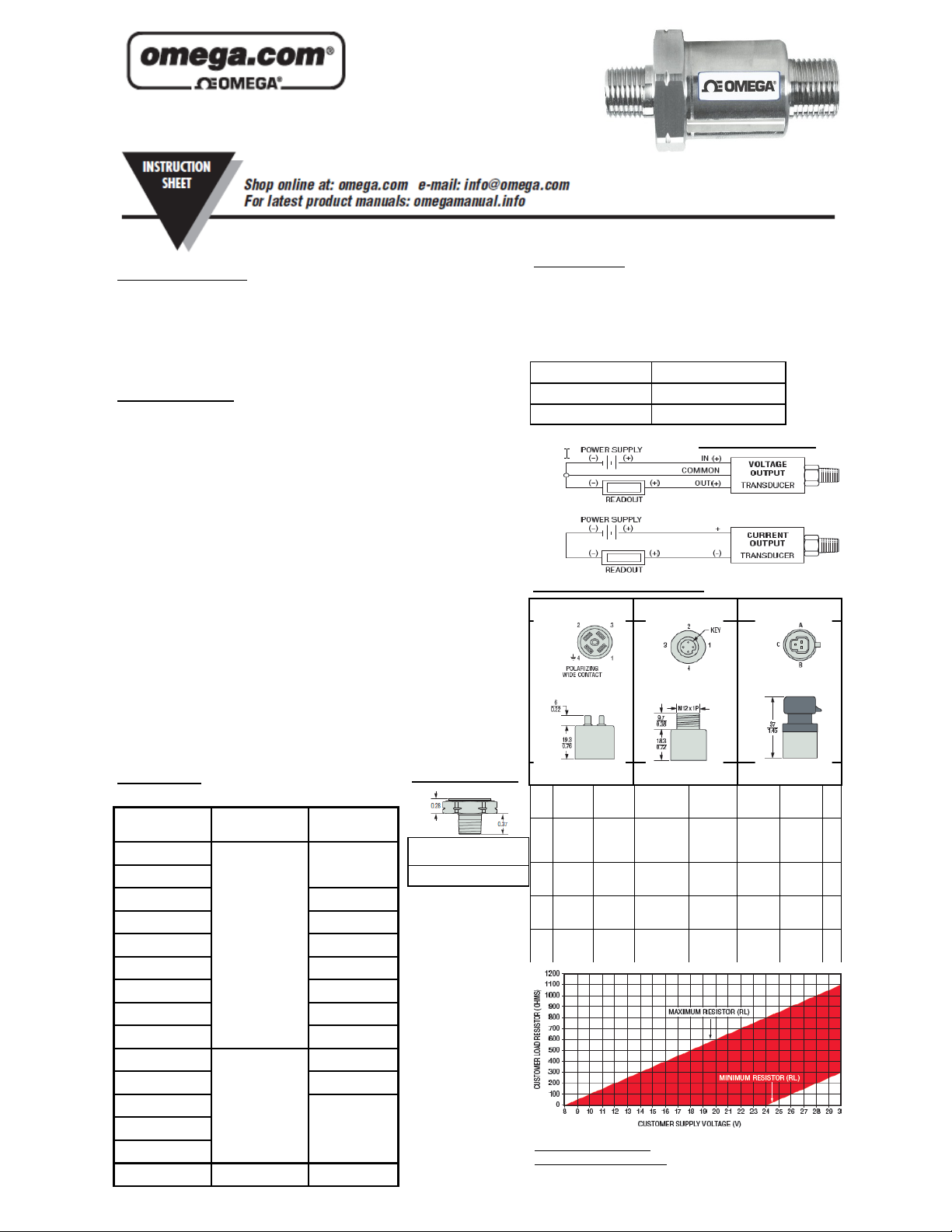
WIRING DIAGRAMS
ELECTRICAL CONNECTORS
Din 9.4 mm M12 x 1P Packard MetriPack
PX171 PX172 PX173
Pin # Voltage
1
2
3
4
CURRENT OUTPUT
MODE (load resistor range)
Current
Mode
Mode
Vsupply Vsupply V
Common Return V
V
No
out
Connect
No
Connect
No
Connect
Voltage
Mode
(pressure
Ground Return V
V
(temp)
Current
Voltage
Mode
Supply V
supply
1
out
2
out
Minimum Resistor Value = 50 + (+V-
24) for +V>24V
Maximum Resistor Value = 50 + (+V-
8) for +V >8V
No
Connect
No
Connect
(pressure
Ground Return
Current
Mode
Mode
1
No
out
Connect
)
Supply
supply
_____ _____
C
A
B
Page 2
239744 rev A
 Loading...