

Page 1
www.omega.com
e-mail: info@omega.com
User’s Guide
PSW-700 SERIES
Pressure Switches
Shop on line at
IMPSW700-01
Page 2

Servicing North America:
USA: One Omega Drive, P.O. Box 4047
ISO 9001 Certified Stamford CT 06907-0047
TEL: (203) 359-1660 FAX: (203) 359-7700
e-mail: info@omega.com
Canada: 976 Bergar
Laval (Quebec) H7L 5A1
TEL: (514) 856-6928 FAX: (514) 856-6886
e-mail: info@omega.ca
For immediate technical or application assistance:
USA and Canada: Sales Service: 1-800-826-6342 / 1-800-TC-OMEGA
®
Customer Service: 1-800-622-2378 / 1-800-622-BEST
®
Engineering Service: 1-800-872-9436 / 1-800-USA-WHEN
®
TELEX: 996404 EASYLINK: 62968934 CABLE: OMEGA
Mexico: En Espan˜ ol: (001) 203-359-7803 e-mail: espanol@omega.com
FAX: (001) 203-359-7807 info@omega.com.mx
Servicing Europe:
Benelux: Postbus 8034, 1180 LA Amstelveen, The Netherlands
TEL: +31 (0)20 6418405 FAX: +31 (0)20 6434643
Toll Free in Benelux: 0800 0993344
e-mail: nl@omega.com
Czech Republic: Rudé armády 1868, 733 01 Karviná 8
TEL: +420 (0)69 6311899 FAX: +420 (0)69 6311114
Toll Free: 0800-1-66342 e-mail: czech@omega.com
France: 9, rue Denis Papin, 78190 Trappes
TEL: +33 (0)130 621 400 FAX: +33 (0)130 699 120
Toll Free in France: 0800-4-06342
e-mail: france@omega.com
Germany/Austria: Daimlerstrasse 26, D-75392 Deckenpfronn, Germany
TEL: +49 (0)7059 9398-0 FAX: +49 (0)7056 9398-29
Toll Free in Germany: 0800 639 7678
e-mail: germany@omega.com
United Kingdom: One Omega Drive, River Bend Technology Centre
ISO 9002 Certified Northbank, Irlam, Manchester
M44 5EX United Kingdom
TEL: +44 (0)161 777 6611 FAX: +44 (0)161 777 6622
Toll Free in United Kingdom: 0800-488-488
e-mail: sales@omega.co.uk
OMEGAnet®On-Line Service Internet e-mail
www.omega.com info@omega.com
It is the policy of OMEGA to comply with all worldwide safety and EMC/EMI regulations that
apply. OMEGA is constantly pursuing certification of its products to the European New Approach
Directives. OMEGA will add the CE mark to every appropriate device upon certification.
The information contained in this document is believed to be correct, but OMEGA Engineering, Inc. accepts
no liability for any errors it contains, and reserves the right to alter specifications without notice.
WARNING: These products are not designed for use in, and should not be used for, patient-connected applications.
Page 3
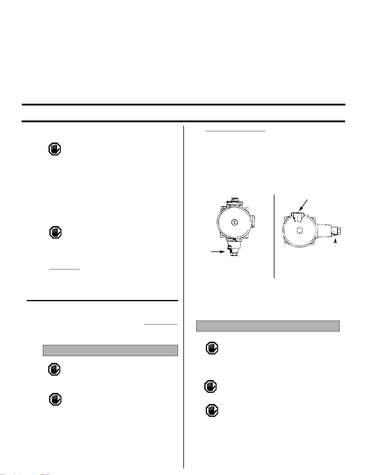
Types PSW-710, 720, 730
Mount controls vertically (pressure connection facing down, See Figure
1a) or horizontally (electrical conduit facing up, See Figure 1b). Either
mounting position will properly orient the venting system. Control may
be surface mounted via the four 1/4" screw holes on the enclosure or
mounting bracket. It can also be mounted directly to a rigid pipe using
the pressure connection.
WIRING
DISCONNECT ALL SUPPLY CIRCUITS BEFORE WIRING
UNIT. WIRE UNITS ACCORDING TO NATIONAL AND LOCAL
ELECTRICAL CODES. MAXIMUM RECOMMENDED WIRE
SIZE IS 14 AWG. THE RECOMMENDED TIGHTENING TORQUE FOR
FIELD WIRING TERMINALS IS 7 TO 17 IN-LBS.
ELECTRICAL RATINGS STATED IN LITERATURE AND ON
NAMEPLATES MUST NOT BE EXCEEDED—OVERLOAD ON
A SWITCH CAN CAUSE FAILURE ON THE FIRST CYCLE.
TO PREVENT SEIZURE OF ENCLOSURE COVER, DO NOT
REMOVE LUBRICANT (PETROLATUM). THREADS SHOULD
ALSO BE FREE OF DIRT, ETC.
GENERAL
MISUSE OF THIS PRODUCT MAY CAUSE EXPLOSION
AND PERSONAL INJURY. THESE INSTRUCTIONS MUST
BE THOROUGHLY READ AND UNDERSTOOD BEFORE
UNIT IS INSTALLED.
The PSW-700 Series pressure and differential pressure
controls are actuated when a bellows, diaphragm or piston sensor
responds to a pressure change. This response at a pre-determined
set point(s) actuates a SPDT, dual SPDT or DPDT snap-acting
microswitch(es), which converts the pressure signal into an electrical signal. Control set point(s) may be varied by turning the internal
adjustment hex (PSW-720, 730) or the external knob and pointer(s)
(PSW-710) according to the procedures outlined below.
PROOF PRESSURE LIMITS STATED IN THE LITERATURE
AND ON NAMEPLATES MUST NEVER BE EXCEEDED,
EVEN BY SURGES IN THE SYSTEM. OCCASIONAL OPERATION OF UNIT UP TO MAXIMUM PRESSURE IS ACCEPTABLE
(E.G. START-UP, TESTING). CONTINUOUS OPERATION SHOULD
NOT EXCEED THE DESIGNATED OVER RANGE PRESSURE.
Proof Pressure
The highest pressure to which a sensing element may be occasionally operated without adversely affecting setpoint calibration and
repeatability.
TOOLS NEEDED
Screwdriver
Adjustable Wrench to 11⁄2"
MOUNTING
ALWAYS HOLD A WRENCH ON THE PRESSURE
HOUSING HEX WHEN MOUNTING UNIT. DO NOT
TIGHTEN BY TURNING ENCLOSURE. THIS WILL DAMAGE
SENSOR AND WEAKEN SOLDER OR WELDED JOINTS.
INSTALL UNITS WHERE SHOCK, VIBRATION AND
TEMPERATURE FLUCTUATIONS ARE MINIMAL. ORIENT
UNIT TO PREVENT MOISTURE FROM ENTERING THE
ENCLOSURE. IT IS IMPERATIVE TO USE PROPERLY RATED
EXPLOSION-PROOF SEALING FITTINGS FOR ELECTRICAL WIRE
ENTRY. DO NOT MOUNT UNIT IN AMBIENT TEMPERATURES
LOWER THAN -40°F (40°C) OR HIGHER THAN 160°F (71°C).
Please read all instructional literature carefully and thoroughly before starting.
UL listed, CSA Certififed,
FM approved
Class I, Division 1, Groups B*, C, D
Class II, Division 2, Groups E, F, G
Class III
Part I - Installation
Explosion-Proof Pressure and
Differential Pressure Switches
Part Numbers: PSW-701 - 717
PSW-721 - 726
PSW-731 - 735
Vent Holes
Figure 1a: PSW-710
Potted Conduit Connection
Figure 1b: PSW-720, 730
Vent Holes
Page 4

Remove cover. Loosen slotted screw adjustment lock. Adjust set
point by turning 5/8” hex adjustment screw clockwise (IN) to
raise set point, or counterclockwise (OUT) to lower set point.
Secure adjustment screw by tightening adjustment lock (see
Figure 3). Internal reference scales are provided to show at which
portion of the range (high or low) the control is set. Re-calibration of models may also require the “re-gapping” of the space
between the top of the plunger and the bottom of the
microswitch. Use the flats on the plunger and plunger hex screw
as reference and follow the gapping instructions.
Types PSW-701-717
Individual microswitches may be set together or apart by up to
100% of range. When not set together, the front microswitch can
not be set higher than the rear microswitch. Turning external
knobs will increase or decrease each switch setting independently. To re-calibrate, follow procedure above for each microswitch.
GAPPING PROCEDURE
TOOLS NEEDED
5/8” Open End Wrench
3/16” Open End Wrench (2)
1) Loosen adjustment lock.
2) Turn 5/8” hex adjustment screw IN, to approximately
mid-range. This puts a load on the sensor and exposes the
plunger flats.
3) Using a 3/16” wrench on the plunger flats and a
3/16” wrench on the plunger hex screw, turn hex
OUT from plunger until microswitch actuates. If
microswitch has already actuated, turn plunger
hex screw IN until microswitch deactuates.
4) Continue per following instructions, depending on model.
PSW-720
Turn hex (IN) an additional 2 flats from this point (approximately
1/3 turn). This will provide a 9-11 mil gap.
PSW-715, 716, 717, 710
Turn hex (IN) 3 flats from this point (approximately 1/2 turn).
This will provide for a 14-16 mil gap.
PSW-731, 732, 733, 734, 735
Turn hex (IN) 1 flat from this point. This will provide a 4-7 mil gap.
Remove cover and wire control (See Figure 2). Replacing cover hand
tight (a minimum of 5 full threads engaged) is sufficient to maintain
proper protection. Additional tightening is required to fully engage
cover O-ring and seal enclosure to rain-tight protection.
TOOLS NEEDED
Screwdriver
5/8” Open End Wrench
5/64” Allen Wrench
SOME MODELS HAVE A TWO-PIECE ADJUSTABLE PLUNGER.
THIS FEATURE IS CHARACTERIZED BY A 3/16” HEX HEAD
SCREW INSTALLED IN THE PLUNGER. THE LENGTH OF THIS
ASSEMBLY IS ADJUSTED AT OUR FACTORY AND IS CRITICAL TO THE
FUNCTION OF THE CONTROL. DURING NORMAL ADJUSTMENT,
THESE COMPONENTS SHOULD NOT BE DISTURBED. HOWEVER,
WHEN REPLACING THE ELECTRICAL SWITCH, IT MAY BE NECESSARY TO ADJUST THE PLUNGER LENGTH IN ORDER TO “RE-GAP”
THE SWITCH. REFER TO INSTRUCTIONS IN PART III REPLACEMENTS TO DETERMINE IF REGAPPING IS NECESSARY.
AFTER COMPLETING ADJUSTMENTS ON TYPE PSW-700, BE
SURE TO RE-INSTALL ADJUSTMENT COVER. DO NOT OVER
TIGHTEN COVER SCREWS.
For set point adjustment and re-calibration, connect control to a calibrated pressure source.
Types PSW-720, 730
Part II - Adjustments
Adjustment Procedure for PSW-720, 730
Plunger Screw
Plunger Flat
Adjust Screw
Use 75°C copper
conductors only.
Recommended
tightening torque for
field wiring terminals
is 7-17 in-lbs.
Types PSW-720, 730
Types PSW-700
HIGH
TERMINAL
BLOCK
HIGH SET
(BACK)
LOW SET
(FRONT)
LOW TERMINAL
BLOCK
Figure 2
Figure 3
Page 5

CONTACT FACTORY FOR ASSISTANCE WITH
MODELS NOT SHOWN ABOVE
TOOLS NEEDED
Screwdrivers, Phillips and Standard
5/8” Open End Wrench
5/64” Allen Wrench
3/16” Open End Wrench (2)
The microswitch is the only factory authorized replacement part. Other
components are factory replaceable.
ALWAYS DISCONNECT THE ELECTRICAL SUPPLY CIRCUITS BEFORE REMOVING EXPLOSION PROOF COVER.
Single Switch Types PSW-720, 730
1) Remove cover; (2) microswitch mounting screws; microswitch
and insulator.
2) Disconnect (3) microswitch wires at microswitch
terminals.
3) Install new microswitch. Wire per PART I.
4) Mount microswitch and insulator inside
enclosure.
5) Check gap per Gapping Procedure.
6) Recalibrate per PART II
Dual Switch Types PSW-700
MICROSWITCHES ARE DIFFERENT FOR OPERATION PURPOSES AND MUST BE INSTALLED ACCORDING TO THE
FOLLOWING PROCEDURE.
Characteristics between front and rear microswitch differ in order to
maintain consistent differential. Replace only with the same
microswitch type.
Follow wiring diagrams exactly. Incorrect wiring will cause controls
to malfunction.
1) Remove cover, unscrew (4) terminal block mounting
screws and remove terminal blocks and insulator.
2) Unhook extension spring from conduit wire guide
and remove wire guide.
3) Remove (2) microswitch mounting screws on low
set microswitch and insulator.
4) Loosen (2) set screws on low set adjusting screw
counter clockwise until switch bracket and actuating
lever assembly can be removed. Be sure that extension
spring is on bracket and washer is on plunger.
5) Turn low set adjusting screw counterclockwise
until the microswitch bracket and actuating lever
assembly can be removed. Be sure the extension
spring is on bracket and the washer is on the plunger.
Note the position of washer, plunger and lever fingers.
6) Unscrew (2) bias plate screws and remove bias plate.
Part III - Replacements
7) Remove (2) microswitch mounting screws,
microswitch and insulator.
8) Disconnect (6) wires at microswitch terminals. Note
the difference between high and low microswitches.
9) Assemble new microswitches and insulators,
mounting high set microswitch to microswitch
bracket and low microswitch to lever assembly.
10) Replace bias plate with flat edge facing conduit
and slot facing sensor assembly.
11) Position low set microswitch bracket and lever
assembly so that fingers of lever are on top of
washer, and turn low set adjustment screw clockwise until lever actuates microswitch.
12) Hook extension spring on to wire guide and
replace insulator and terminal blocks.
13) Tighten allen set screws and install terminal
blocks. Wire per Part I.
14) Re-calibrate per Part II.
15) Replace cover.
Page 6

Internal Set Point Adjustment
PSW-721-726, 731-735
External Set Point Adjustment
PSW-701-717
Dimensions
PSW-701, 711-714
PSW-702-704, 708, 709
PSW-731-735
Pressure
Dimension A
Models Inches mm NPT
Pressure
PSW-721-726 8.56 217.4 1/2
PSW-731-735 7.19 182.6 1/2
Dimension A
Models Inches mm NPT
Pressure
PSW-701, 711-714 8.50 215.9 1/4
PSW-702-704 &
PSW-708-709 8.84 244.5 1/2
PSW-710 8.75 222.3 1/4
PSW-705-707 7.81 198.4 1/4
PSW-715-717 8.31 211.1 1/4
PSW-710, 715-717
PSW-721-726
PSW-705-707
1/2
Page 7

WARRANTY/DISCLAIMER
OMEGA ENGINEERING, INC. warrants this unit to be free of defects in materials and workmanship for a
period of 13 months from date of purchase. OMEGA’s WARRANTY adds an additional one (1) month
grace period to the normal one (1) year product warranty to cover handling and shipping time. This
ensures that OMEGA’s customers receive maximum coverage on each product.
If the unit malfunctions, it must be returned to the factory for evaluation. OMEGA’s Customer Service
Department will issue an Authorized Return (AR) number immediately upon phone or written request.
Upon examination by OMEGA, if the unit is found to be defective, it will be repaired or replaced at no
charge. OMEGA’s WARRANTY does not apply to defects resulting from any action of the purchaser,
including but not limited to mishandling, improper interfacing, operation outside of design limits,
improper repair, or unauthorized modification. This WARRANTY is VOID if the unit shows evidence of
having been tampered with or shows evidence of having been damaged as a result of excessive corrosion;
or current, heat, moisture or vibration; improper specification; misapplication; misuse or other operating
conditions outside of OMEGA’s control. Components which wear are not warranted, including but not
limited to contact points, fuses, and triacs.
OMEGA is pleased to offer suggestions on the use of its various products. However,
OMEGA neither assumes responsibility for any omissions or errors nor assumes liability for any
damages that result from the use of its products in accordance with information provided by
OMEGA, either verbal or written. OMEGA warrants only that the parts manufactured by it will be
as specified and free of defects. OMEGA MAKES NO OTHER WARRANTIES OR
REPRESENTATIONS OF ANY KIND WHATSOEVER, EXPRESS OR IMPLIED, EXCEPT THAT OF TITLE,
AND ALL IMPLIED WARRANTIES INCLUDING ANY WARRANTY OF MERCHANTABILITY AND
FITNESS FOR A PARTICULAR PURPOSE ARE HEREBY DISCLAIMED. LIMITATION OF
LIABILITY: The remedies of purchaser set forth herein are exclusive, and the total liability of
OMEGA with respect to this order, whether based on contract, warranty, negligence,
indemnification, strict liability or otherwise, shall not exceed the purchase price of the
component upon which liability is based. In no event shall OMEGA be liable for
consequential, incidental or special damages.
CONDITIONS: Equipment sold by OMEGA is not intended to be used, nor shall it be used: (1) as a “Basic
Component” under 10 CFR 21 (NRC), used in or with any nuclear installation or activity; or (2) in medical
applications or used on humans. Should any Product(s) be used in or with any nuclear installation or
activity, medical application, used on humans, or misused in any way, OMEGA assumes no responsibility
as set forth in our basic WARRANTY/ DISCLAIMER language, and, additionally, purchaser will indemnify
OMEGA and hold OMEGA harmless from any liability or damage whatsoever arising out of the use of the
Product(s) in such a manner.
RETURN REQUESTS/INQUIRIES
Direct all warranty and repair requests/inquiries to the OMEGA Customer Service Department. BEFORE
RETURNING ANY PRODUCT(S) TO OMEGA, PURCHASER MUST OBTAIN AN AUTHORIZED RETURN
(AR) NUMBER FROM OMEGA’S CUSTOMER SERVICE DEPARTMENT (IN ORDER TO AVOID
PROCESSING DELAYS). The assigned AR number should then be marked on the outside of the return
package and on any correspondence.
The purchaser is responsible for shipping charges, freight, insurance and proper packaging to prevent
breakage in transit.
FOR W
ARRANTY RETURNS, please have the
following information available BEFORE
contacting OMEGA:
1. Purchase Order number under which the product
was PURCHASED,
2. Model and serial number of the product under
warranty, and
3. Repair instructions and/or specific problems
relative to the product.
FOR NON-WARRANTY REPAIRS,
consult OMEGA
for current repair charges. Have the following
information available BEFORE contacting OMEGA:
1. Purchase Order number to cover the COST
of the repair,
2. Model and serial number of the product, and
3. Repair instructions and/or specific problems
relative to the product.
OMEGA’s policy is to make running changes, not model changes, whenever an improvement is possible. This affords
our customers the latest in technology and engineering.
OMEGA is a registered trademark of OMEGA ENGINEERING, INC.
© Copyright 2000 OMEGA ENGINEERING, INC. All rights reserved. This document may not be copied, photocopied,
reproduced, translated, or reduced to any electronic medium or machine-readable form, in whole or in part, without the
prior written consent of OMEGA ENGINEERING, INC.
Page 8

M-1102/0500
Where Do I Find Everything I Need for
Process Measurement and Control?
OMEGA…Of Course!
Shop on line at www.omega.com
TEMPERATURE
Thermocouple, RTD & Thermistor Probes, Connectors, Panels & Assemblies
Wire: Thermocouple, RTD & Thermistor
Calibrators & Ice Point References
Recorders, Controllers & Process Monitors
Infrared Pyrometers
PRESSURE, STRAIN AND FORCE
Transducers & Strain Gages
Load Cells & Pressure Gages
Displacement Transducers
Instrumentation & Accessories
FLOW/LEVEL
Rotameters, Gas Mass Flowmeters & Flow Computers
Air Velocity Indicators
Turbine/Paddlewheel Systems
Totalizers & Batch Controllers
pH/CONDUCTIVITY
pH Electrodes, Testers & Accessories
Benchtop/Laboratory Meters
Controllers, Calibrators, Simulators & Pumps
Industrial pH & Conductivity Equipment
DATA ACQUISITION
Data Acquisition & Engineering Software
Communications-Based Acquisition Systems
Plug-in Cards for Apple, IBM & Compatibles
Datalogging Systems
Recorders, Printers & Plotters
HEATERS
Heating Cable
Cartridge & Strip Heaters
Immersion & Band Heaters
Flexible Heaters
Laboratory Heaters
ENVIRONMENTAL
MONITORING AND CONTROL
Metering & Control Instrumentation
Refractometers
Pumps & Tubing
Air, Soil & Water Monitors
Industrial Water & Wastewater Treatment
pH, Conductivity & Dissolved Oxygen Instruments
 Loading...