

Page 1
omega.com
e-mail: info@omega.com
For latest product manuals:
omegamanual.info
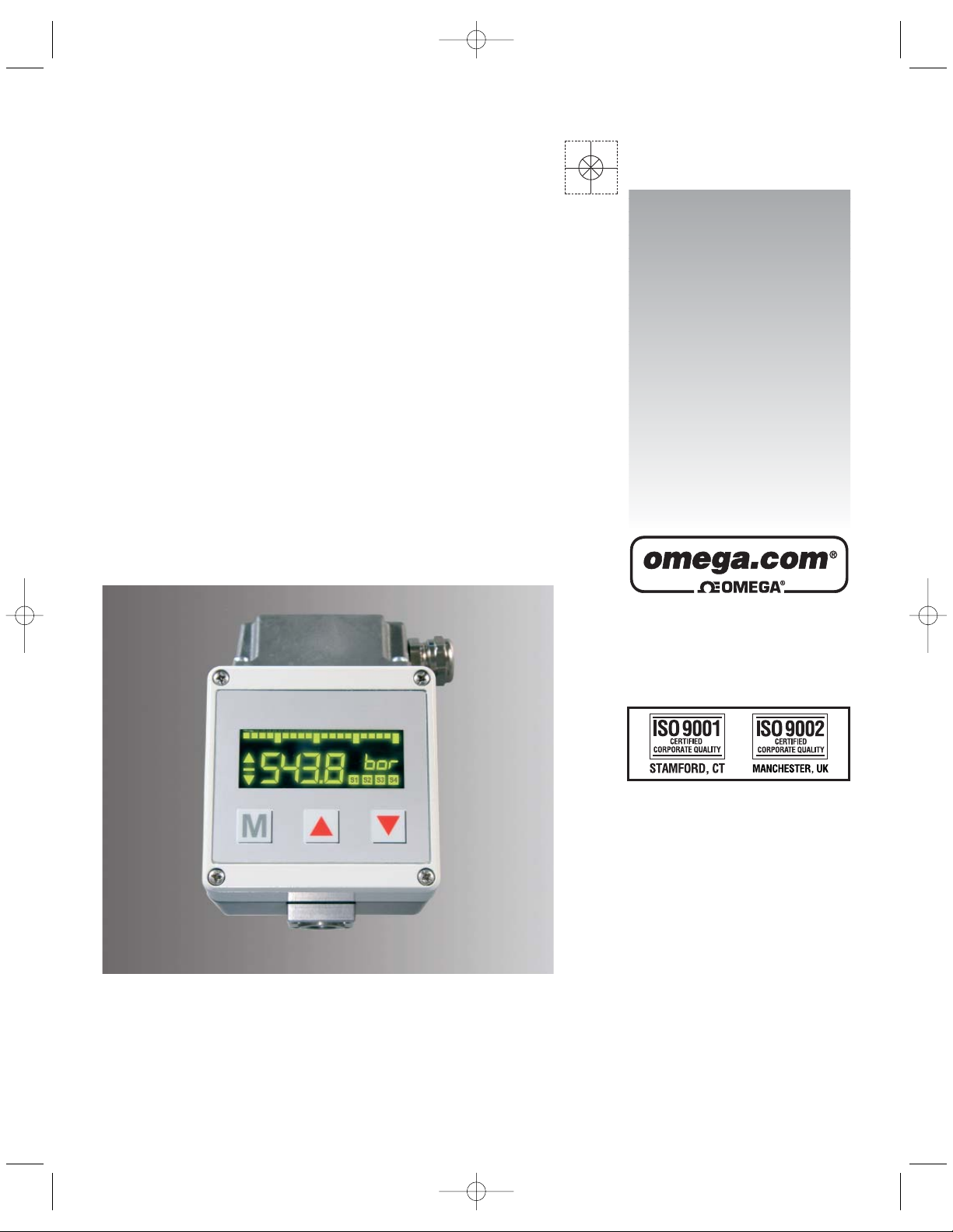
PSW3000
Operating Instructions Pressure Switch
with 4 Relay Outputs
Shop online at
User
’
s Guide
PSW3000.qxp 6/12/2008 10:48 AM Page cov-3
Page 2

2
Servicing North America:
U.S.A.: One Omega Drive, P.O. Box 4047
ISO 9001 Certified Stamford, CT 06907-0047
TEL: (203) 359-1660
FAX: (203) 359-7700
e-mail: info@omega.com
Canada: 976 Bergar
Laval (Quebec) H7L 5A1, Canada
TEL: (514) 856-6928
FAX: (514) 856-6886
e-mail: info@omega.ca
For immediate technical or application assistance:
U.S.A. and Canada: Sales Service: 1-800-826-6342/1-800-TC-OMEGA
®
Customer Service: 1-800-622-2378/1-800-622-BEST
®
Engineering Service: 1-800-872-9436/1-800-USA-WHEN
®
Mexico: En Espan˜ ol: (001) 203-359-7803
e-mail: espanol@omega.com
FAX: (001) 203-359-7807
info@omega.com.mx
Servicing Europe:
Czech Republic: Frystatska 184, 733 01 Karviná, Czech Republic
TEL: +420 (0)59 6311899
FAX: +420 (0)59 6311114
Toll Free: 0800-1-66342
e-mail: info@omegashop.cz
Germany/Austria: Daimlerstrasse 26, D-75392 Deckenpfronn, Germany
TEL: +49 (0)7056 9398-0
FAX: +49 (0)7056 9398-29
Toll Free in Germany: 0800 639 7678
e-mail: info@omega.de
United Kingdom: One Omega Drive, River Bend Technology Centre
ISO 9002 Certified Northbank, Irlam, Manchester
M44 5BD United Kingdom
TEL: +44 (0)161 777 6611
FAX: +44 (0)161 777 6622
Toll Free in United Kingdom: 0800-488-488
e-mail: sales@omega.co.uk
OMEGAnet®Online Service Internet e-mail
omega.com info@omega.com
It is the policy of OMEGA Engineering, Inc. to comply with all worldwide safety and EMC/EMI
regulations that apply. OMEGA is constantly pursuing certification of its products to the European New
Approach Directives. OMEGA will add the CE mark to every appropriate device upon certification.
The information contained in this document is believed to be correct, but OMEGA accepts no liability for any
errors it contains, and reserves the right to alter specifications without notice.
WARNING: These products are not designed for use in, and should not be used for, human applications.
PSW3000.qxp 6/12/2008 10:48 AM Page cov-4
Page 3
3
1. Product Description
2. Starting operations
Intended Applications
- The pressure switch / trip amplifier is a device to monitor system pressure, temperature,
flow, level, etc. and has four switching outputs and one analog output.
- The pressure switch is only to be installed in systems where the maximum pressure Pmax is
not exceeded (according to the values on the type label).
- Attention: This device is not designed to be used as the only safety relevant element in
pressurized systems according PED 97/23/EC.
Only assemble or disassemble the device when depressurized!
- The pressure switch should be installed and operated only by authorized personel.
- Front cover and device bottom form a function unit. Exchanging the parts can result in
measuring errors or malfunctioning. See serial number inside the front cover. For wall
mounting, remove the four front cover screws and the front cover, then fasten the device with
four screws to the wall, and finally remount the front cover. To damp strong vibrations shock,
mounts must be used.
- Mount the pressure connection (G 1/4 female) of the PSW3000 to the pressure system with a
flexible pipe and tighten with a 45 Nm torque. For pressure peaks damping, screws must be
used.
- The electrical connection (supply, analog output switching contacts) must be carried out
according to the connection tables depicted on the top of the device by removing the cover
cap and insert the cable through the cable gland PG 13,5. If required, additional cable glands
can be installed in the cover cap by breaking out the perforated cavities.
- The electrical connection must be carried out in accordance with the VDE 0100 regulations. In
order to ensure trouble-free operation it is essential to connect the protective lead.
When operating from 230 V AC loads at the switch contacts independent cables must be
installed for supply and switches (cover cap with two cable screw connections).
- If inductive loads (magnets, contactors, etc.) are connected to the switch relays, suitable
protective devices (varistors etc.) must be provided.
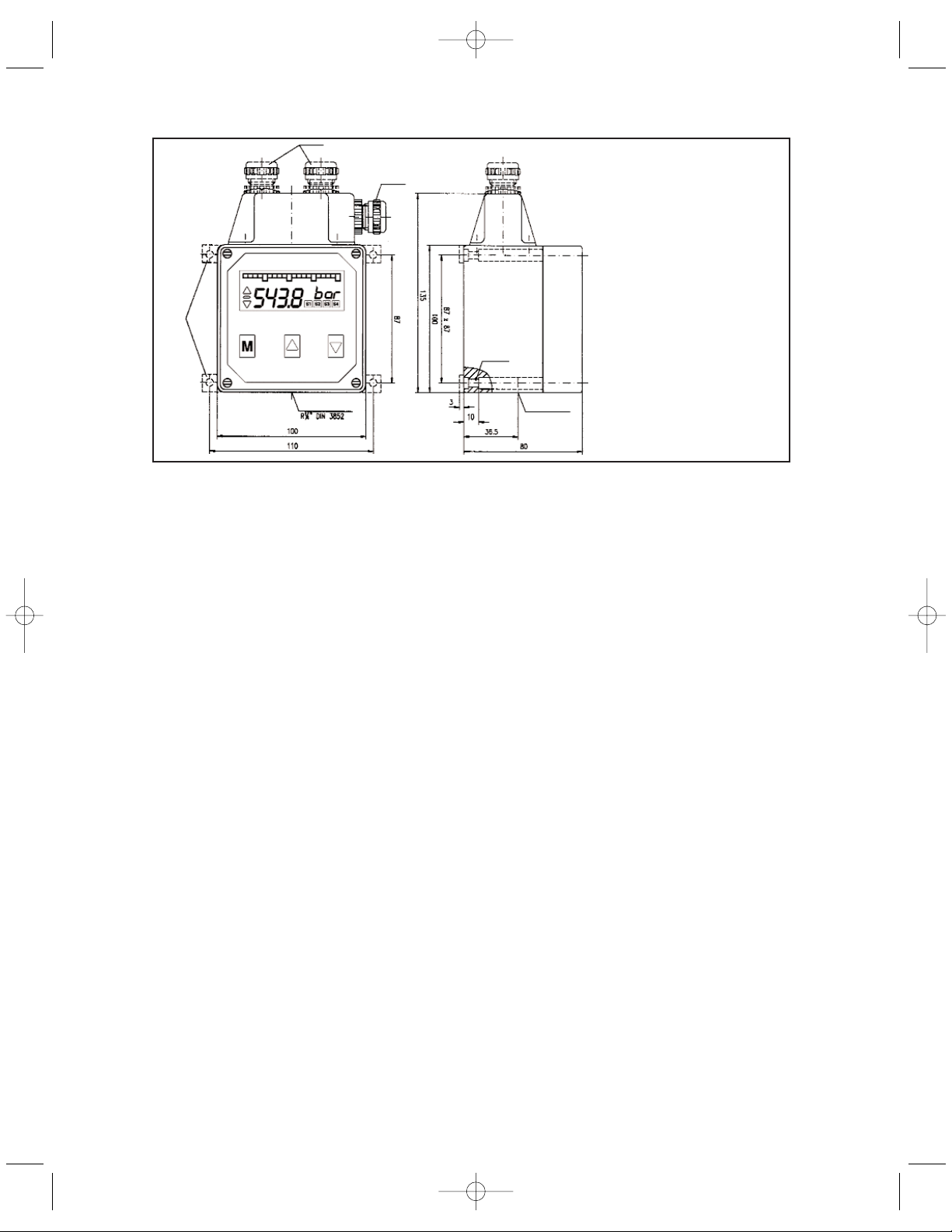
PSW3000
Dimensions (in mm)
PSW3000.qxp 6/12/2008 10:48 AM Page cov-5
Page 4

3. Operating elements
Contact rating : max. 120 V DC / 250 V AC
Switching power : max. 120 W / 1250 V AC
Switching capacitiy : 220 V AC / 3 A VDE 0660 T.2
Constant current : max. 5 A
Switching rate : max. 20/s
20-part bargraph
Sign
Trend arrows
Menu buttons
8-digit 14-segment display
Switchpoint display SP1...SP4
Cover screws
4
PSW3000.qxp 6/12/2008 10:48 AM Page cov-6
Page 5

Main Menu Sub Menu Value Description
Measuring
mode
.... Display of the actually measured value and the measuring
unit
MENU
UNLK
LOCK
Display keylock
No keylock, all parameters can be adjusted
Keylock active, all parameters visibal but can not be
changed
SP.1 ... SP.4
MODE
ON
OFF
LEV
DEL
STND
WIND
ERRO
....
....
HLFS
LLFS
0,0s..9,9 s
Switchpoint menu SP1..SP4
Standard evaluation (rising/falling)
Window technology
Error output
Switch-on value for SP1..SP4; if the ON-value is smaller
than the OFF-value, the switch evaluatiuon is falling
Switch-off value SP1..SP4
Inversion of the switching output SP1...SP4
High-level-fail-safe (Normally Open function)
Low-level-fail-save (Normally Closed function)
Switch-on / switch-off delay for SP1...SP2 in seconds
ANOP
ANOP
AOZS
AOFS
ON
OFF
....
Analog output menu
Analog output in operation
Analog output switched off
Scale the analog output - start value (e.g. 0 bar=4mA)
Scale the analog output - end value (e.g. 400bar=20mA)
DISP
UNIT
DAMP
OFFS
CUT
BGZS
BGFS
bar
PSI
MPa
0,0s..9,9 s
....
....
....
....
Display menu
Adjustment of the measuring unit, the recalculation to the
new unit value is done automatically
Damping of the displayed measuring value in seconds
Measuring value -Offset, means shifting the display range
Cut-Off, means signal-surpression within the cut-off
range
Scale the bargraph - start value
Scale the bargraph - end value
PEAK
MIN
CLRM
MAX
CLRX
....
NO
YES
....
NO
YES
Peakholding menu
Display the peak value “Min“
no deletion
delete “Min“ -value
Display the peak value “Max“
no deletion
delete “Max“ -value
List of functions:
5
PSW3000.qxp 6/12/2008 10:48 AM Page cov-7
Page 6

Display Error Cause
max Positive excess of the measuring range The measured value exceeds the max. of the range
min Negative excess of the measuring range The measured value is lower than the min. of the range
anao Failure of the analog output Output loop is not closed or short circuited
sens Sensor failure (internal) Sensor bridge not in balance, might be been overloade
data Stored data failure (EEProm) (internal) Memory failure
prog Processor failure (internal) Microcontroller failure
cal Calibration failure (internal) Calibration values are wrong
6
4. Operation
After the unit is switched on, the unit starts an automatic self-test.
The device is menu operated and configured by the three keys on the front.
With the “M“ key (= mode) you change between the operation / indicating level to the dialog
values and the adjusted / actual values. With the keys (““= up) and (““= down) you change
between the dialog values in the menu or change the values / functions in the menus.
A change of any configuration starts always with the M-Mode and indicated by the flashing
cursor. After a change has been made the M-mode key must be pressed to confirm each
configuration; to set numbers, each digit has to be confirmed with the M-Mode before adjusting
the next one. By confirming the last digit the new configuration will be stored in the memory.
Pushing the down key at the end of the sub-menu the software will switch automatically to the
main-menu.
For a quick termination of programming you can change into the measuring mode from any level in the menu
by pressing the M-key for 5 seconds.
If the dialog is not continued within two minutes the device automatically returns to the measuring mode
without accepting the new values (see also: “List of functions“).
5. Key lock
Activating the (““= up) and (““= down) keys together for more than 5 seconds will block any
changings in all menues; shown by “LOCK“ in the display.
In this mode, all configuration values can be checked only, but not changed.
Repeating this action will unlock the configuration menu and shown by “UNLK“ in the display.
6. Error handling
The internal self-check software will monitor the proper functioning of the unit. When any of the following
failures will occur, the flashing display will indicate the following text:
PSW3000.qxp 6/12/2008 10:48 AM Page cov-8
Page 7

7
PSW3000.qxp 6/12/2008 10:48 AM Page cov-9
Page 8

WARRANTY/DISCLAIMER
OMEGA ENGINEERING, INC. warrants this unit to be free of defects in materials and workmanship for a
period of 13 months from date of purchase. OMEGA’s WARRANTY adds an additional one (1) month
grace period to the normal one (1) year product warranty to cover handling and shipping time. This
ensures that OMEGA’s customers receive maximum coverage on each product.
If the unit malfunctions, it must be returned to the factory for evaluation. OMEGA’s Customer Service
Department will issue an Authorized Return (AR) number immediately upon phone or written request.
Upon examination by OMEGA, if the unit is found to be defective, it will be repaired or replaced at no
charge. OMEGA’s WARRANTY does not apply to defects resulting from any action of the purchaser,
including but not limited to mishandling, improper interfacing, operation outside of design limits,
improper repair, or unauthorized modification. This WARRANTY is VOID if the unit shows evidence of
having been tampered with or shows evidence of having been damaged as a result of excessive corrosion;
or current, heat, moisture or vibration; improper specification; misapplication; misuse or other operating
conditions outside of OMEGA’s control. Components in which wear is not warranted, include but are not
limited to contact points, fuses, and triacs.
OMEGA is pleased to offer suggestions on the use of its various products. However,
OMEGA neither assumes responsibility for any omissions or errors nor assumes liability for any
damages that result from the use of its products in accordance with information provided by
OMEGA, either verbal or written. OMEGA warrants only that the parts manufactured by the
company will be as specified and free of defects. OMEGA MAKES NO OTHER WARRANTIES OR
REPRESENTATIONS OF ANY KIND WHATSOEVER, EXPRESSED OR IMPLIED, EXCEPT THAT OF
TITLE, AND ALL IMPLIED WARRANTIES INCLUDING ANY WARRANTY OF MERCHANTABILITY
AND FITNESS FOR A PARTICULAR PURPOSE ARE HEREBY DISCLAIMED. LIMITATION OF
LIABILITY: The remedies of purchaser set forth herein are exclusive, and the total liability of
OMEGA with respect to this order, whether based on contract, warranty, negligence,
indemnification, strict liability or otherwise, shall not exceed the purchase price of the
component upon which liability is based. In no event shall OMEGA be liable for
consequential, incidental or special damages.
CONDITIONS: Equipment sold by OMEGA is not intended to be used, nor shall it be used: (1) as a “Basic
Component” under 10 CFR 21 (NRC), used in or with any nuclear installation or activity; or (2) in medical
applications or used on humans. Should any Product(s) be used in or with any nuclear installation or
activity, medical application, used on humans, or misused in any way, OMEGA assumes no responsibility
as set forth in our basic WARRANTY/DISCLAIMER language, and, additionally, purchaser will indemnify
OMEGA and hold OMEGA harmless from any liability or damage whatsoever arising out of the use of the
Product(s) in such a manner.
RETURN REQUESTS/INQUIRIES
Direct all warranty and repair requests/inquiries to the OMEGA Customer Service Department. BEFORE
RETURNING ANY PRODUCT(S) TO OMEGA, PURCHASER MUST OBTAIN AN AUTHORIZED RETURN
(AR) NUMBER FROM OMEGA’S CUSTOMER SERVICE DEPARTMENT (IN ORDER TO AVOID
PROCESSING DELAYS). The assigned AR number should then be marked on the outside of the return
package and on any correspondence.
The purchaser is responsible for shipping charges, freight, insurance and proper packaging to prevent
breakage in transit.
FOR W
ARRANTY RETURNS, please have the
following information available BEFORE
contacting OMEGA:
1. Purchase Order number under which the product
was PURCHASED,
2. Model and serial number of the product under
warranty, and
3. Repair instructions and/or specific problems
relative to the product.
FOR NON-WARRANTY REPAIRS,
consult OMEGA
for current repair charges. Have the following
information available BEFORE contacting OMEGA:
1. Purchase Order number to cover the COST
of the repair,
2. Model and serial number of the product, and
3. Repair instructions and/or specific problems
relative to the product.
OMEGA’s policy is to make running changes, not model changes, whenever an improvement is possible. This affords
our customers the latest in technology and engineering.
OMEGA is a registered trademark of OMEGA ENGINEERING, INC.
© Copyright 2007 OMEGA ENGINEERING, INC. All rights reserved. This document may not be copied, photocopied,
reproduced, translated, or reduced to any electronic medium or machine-readable form, in whole or in part, without the
prior written consent of OMEGA ENGINEERING, INC.
PSW3000.qxp 6/12/2008 10:48 AM Page cov-10
Page 9

M-4676/0508
Where Do I Find Everything I Need for
Process Measurement and Control?
OMEGA…Of Course!
Shop online at omega.com
TEMPERATURE
䡺⻬
Thermocouple, RTD & Thermistor Probes, Connectors, Panels & Assemblies
䡺⻬
Wire: Thermocouple, RTD & Thermistor
䡺⻬
Calibrators & Ice Point References
䡺⻬
Recorders, Controllers & Process Monitors
䡺⻬
Infrared Pyrometers
PRESSURE, STRAIN AND FORCE
䡺⻬
Transducers & Strain Gages
䡺⻬
Load Cells & Pressure Gages
䡺⻬
Displacement Transducers
䡺⻬
Instrumentation & Accessories
FLOW/LEVEL
䡺⻬
Rotameters, Gas Mass Flowmeters & Flow Computers
䡺⻬
Air Velocity Indicators
䡺⻬
Turbine/Paddlewheel Systems
䡺⻬
Totalizers & Batch Controllers
pH/CONDUCTIVITY
䡺⻬
pH Electrodes, Testers & Accessories
䡺⻬
Benchtop/Laboratory Meters
䡺⻬
Controllers, Calibrators, Simulators & Pumps
䡺⻬
Industrial pH & Conductivity Equipment
DATA ACQUISITION
䡺⻬
Data Acquisition & Engineering Software
䡺⻬
Communications-Based Acquisition Systems
䡺⻬
Plug-in Cards for Apple, IBM & Compatibles
䡺⻬
Datalogging Systems
䡺⻬
Recorders, Printers & Plotters
HEATERS
䡺⻬
Heating Cable
䡺⻬
Cartridge & Strip Heaters
䡺⻬
Immersion & Band Heaters
䡺⻬
Flexible Heaters
䡺⻬
Laboratory Heaters
ENVIRONMENTAL
MONITORING AND CONTROL
䡺⻬
Metering & Control Instrumentation
䡺⻬
Refractometers
䡺⻬
Pumps & Tubing
䡺⻬
Air, Soil & Water Monitors
䡺⻬
Industrial Water & Wastewater Treatment
䡺⻬
pH, Conductivity & Dissolved Oxygen Instruments
PSW3000.qxp 6/12/2008 10:48 AM Page cov-2
 Loading...