

Page 1
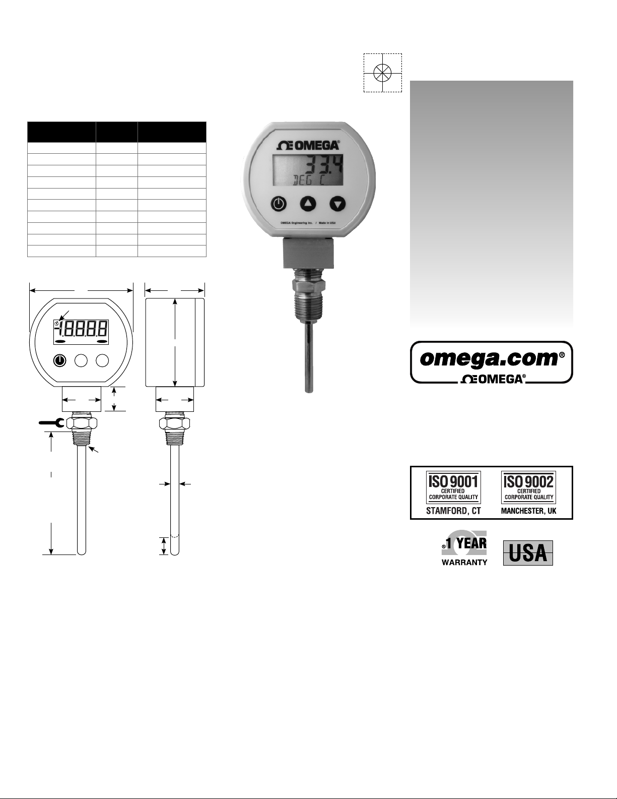
PRTXB Series
RTD Process Thermometers
M-4998/1110
3.5"
8
8
8
PROBE
LENGTH
2.5"
2.5"
4"
4"
6"
6"
9"
9"
12"
12"
ALARM 2
MODEL
PRTXB-2
PRTXB-2-SL
PRTXB-4
PRTXB-4-SL
PRTXB-6
PRTXB-6-SL
PRTXB-9
PRTXB-9-SL
PRTXB-12
PRTXB-12-SL
*
Thermowell required for spring-loaded versions
Low battery
indication
ALARM 1
XXXXX
8
8
PROBE
TYPE
Fixed
Spring-Loaded
Fixed
Spring-Loaded
Fixed
Spring-Loaded
Fixed
Spring-Loaded
Fixed
Spring-Loaded
2.0"
3.0"
User’s Guide
*
*
*
*
*
Shop online at
Turn at
hex
fitting
only!
Stem
Length
Measured from
top of full threads
to tip of probe.
Length L =
thermowell “A” or
“element length”
Range and Resolution
–58.0°F to 392.0°F, –50.0°C to 200.0°C or 220K to 475K
0.1 degree resolution
User selectable °F, °C, or K
Accuracy
Includes linearity, hysteresis, repeatability
±0.3°C at 0°C, ±1.1°C at 150°C
11-point linearization table
Display
4 readings per second nominal display update rate
4 digit LCD, 0.5" H, 5 character 0.25" H alphanumeric
BL models: red LED backlight
Sensor
IEC-751 Class B 100 Platinum RTD, 0.00385 alpha curve
1
/2" NPT male, 316 stainless steel
Spring-loaded probe versions fit standard thermowells
Auto Shutoff Time
Factory default 5 minutes. User settable to 1, 2, 5, 10, 15, 20,
30 minutes, 1, 2, 4, 8 hours, or manual on/off.
OFF warning before auto shutoff to allow reset of timer
1.37"
L
0.75"
Hex nipple
1/2" NPT x 1/2" NPT
316 stainless
Continuous weld
on non-spring
loaded models
Spring-loaded models
approx. 0.25" longer
to compress element
in thermowell.
0.50" max.
compression
0.25" dia.
1.25"
Batteries, Battery Life, Low Battery Indication
B: 2 AA alkaline, approx. 1000 hours
BL: 2 AA alkaline, approx. 150 to 750 hours depending on
backlight usage.
BL: Button press activates backlighting for 1 minute
Low battery symbol on display
Controls and Functions
Three front buttons for power on/off, min/max functions,
selection of °F, °C, or K, auto shutoff times, calibration and,
configuration options
User-defined pass codes for configuration and calibration to
prevent unauthorized changes
Maximum and Minimum Readings
User-configurable maximum and/or minimum temperature
indication. Factory default configuration MAX/MIN disabled.
Choice of MAX only, MIN only, MAX/MIN, or none
Option to retain or clear MAX/MIN temperatures at shutoff
Out-of-Range
ALARM1 under range indication on display
ALARM2 over range indication on display
omega.com
e-mail: info@omega.com
For latest product manuals:
omegamanual.info
MADE IN
Calibration
User settable pass code required to enter calibration mode
Zero and span temperature calibration
Non-interactive zero, span, and linearity, ±10% of range
Weight
Product: 12 ounces (approximately)
Shipping: 1 pound (approximately)
Housing
ABS/polycarbonate NEMA 4X case, polycarbonate label, rubber
rear gasket
Connection, Material, Media Compatibility
1/2" NPT male fitting, 316L stainless steel
All wetted parts are 316L stainless steel
Thermowell required for spring-loaded versions
Storage Temperature
–40 to 203°F (–40 to 95°C)
Operating Range
–4 to 185°F (–20 to 85°C) at housing
Page 2
2
PRTXB Series RTD Process Thermometers
Description
The PRTXB series is microprocessor controlled industrial RTD
temperature indicator with a digital temperature display in a
rugged NEMA 4X housing.
The temperature reading is linearized for the digital display. The
temperature display may be set up to read °F, °C, or kelvin and
the auto shutoff time may be set as needed.
The unit is capable of automatically capturing and storing
maximum and maximum readings. The min/max functionality
can be set up as required, and the readings can be either saved
or cleared when the unit shuts off.
Installation and Precautions
Read these instructions before installation. Configuration may
be easier before installation.
The spring-loaded versions must be used with a thermowell.
Use a thermowell appropriate for the process.
The non-spring-loaded versions can be used in non-pressurized
applications or applications with no flow. Due to the hardness of
316 stainless steel, it is recommended that a thread sealant be
used to ensure leak-free operation.
Do not exceed maximum allowable housing temperature.
Install or remove using wrench on probe hex fitting only. Do not
attempt to tighten or loosen by turning the housing.
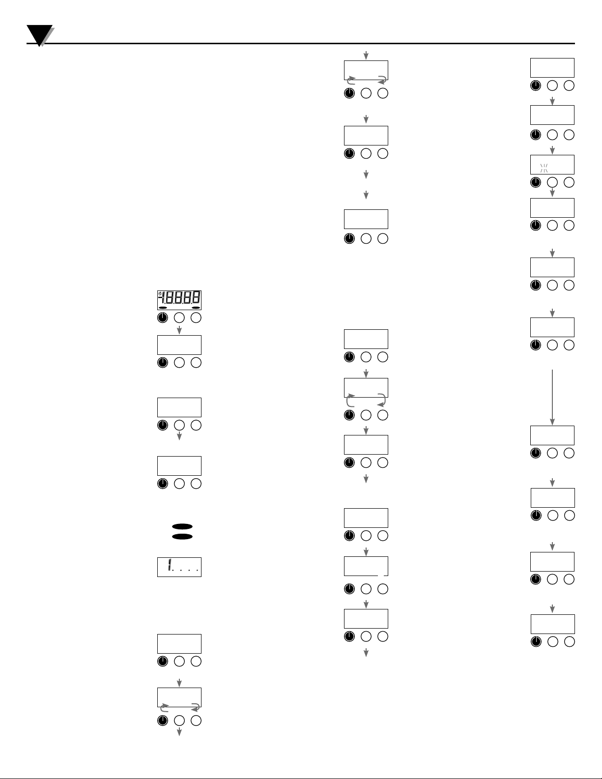
Operation
Press and release the power button to power
up the unit. The unit tests all LCD segments
and displays the RTD temperature on the
upper display and the temperature units on
the lower display. Readings are updated
approximately 4 times per second.
The RTD probe has a time constant of
approximately 10 seconds, typical of an RTD
probe in a stainless sheath. Time constant is
characterized as the RTD changing to 63.2%
of its new temperature span in one time
constant, and 95% of its new temperature
span in three time constants.
If the unit is configured with an auto shutoff
time, a five second warning period is
provided prior to auto shutoff, during which
the display indicates OFF. The auto shutoff
timer is reset whenever any button is pressed
and released.
To shut off the unit manually at any time,
press and hold the power button until the
display indicates OFF (up to about 5 seconds
total if MAX/MIN is enabled) and then release
the button.
Out-of-Range Indications
If the RTD temperature goes above 392°F or
200°C, ALARM1 will be displayed.
If the RTD temperature goes below –58°F or
–50°C, ALARM2 will be displayed.
If the RTD temperature continues beyond
these limits, the display will eventually
indicate 1.-.-.-.
MAX/MIN Operation (if enabled)
The factory default setting has min/max disabled. To turn this
feature on, see the section titled User Configuration Mode. The
unit may be configure to use max, min, neither, or both.
To step the unit through the display modes,
press and hold the power button about 1
second until the display indicates MAX or
MIN and then release the button. The display
mode cycle repeats through the following
steps.
MAX Mode
The display indicates the stored maximum
reading and the lower display alternates
between indicating MAX and the temperature
units. The thermometer may be left in this
mode if desired.
ALARM 1
XXXXX
8
8
8
ALARM 2
8
8
75.0
deg f
off
deg f
Press any button to
keep on
75.0
deg f
Press and hold
to turn off
ALARM 1
ALARM 2
DEG F
75.0
deg f
Press and hold
about 1 sec.
i25.5
deg f
max
MIN Mode
Press and hold the power button about 1
second The display indicates the stored
minimum reading and the lower display
alternates between indicating MIN and the
temperature units. The thermometer may be
left in this mode if desired.
Return to Normal Mode
To return from minimum or maximum
reading mode to the normal operating
mode, press and hold the power button for
about 1 second until the display indicates
the temperature units and then release the
button. The unit returns to the normal mode.
The stored maximum and minimum values
are not cleared and continue to be updated.
Reset MAX and MIN
To manually reset the stored maximum
and minimum readings, press and continue
to hold the power button until the display
indicates clr (about 3 seconds total) and then
release the button. The stored maximum and
minimum values are cleared. The unit returns
to the normal mode.
The Min/Max memory may be configured to be automatically
cleared when the unit shuts down, or may be configured to
retain the values when the unit is shut off. See the section titled
User Configuration Mode for these options.
Temperature Unit Selection
To change temperature units, press and hold
the button until the temperature indication
is blanked and only the temperature units are
displayed.
Then use the and buttons to select the
desired temperature units. Standard units are
Fahrenheit, Celsius, and kelvin.
When the desired units are displayed, press
and release the power button to save the
selection and exit the change mode.
If no buttons are pressed for 15 seconds, the
unit will automatically save the selection and
exit the change mode.
Auto Shutoff Time Selection
To change the auto shutoff time, press and
hold the button until the auto shutoff time
is displayed.
The lower display will indicate AST M if the
auto shutoff time displayed is in minutes, and
AST H if it is in hours.
An auto shutoff time of zero signifies that the
auto shutoff feature is disabled.
Use the and buttons to select 0, or 1,
2, 5, 10, 15, 20, or 30 minutes, or 1, 2, 4,
or 8 hours.
When the desired auto shutoff time is
displayed, press and release the power
button to save the selection and exit the
change mode.
If no buttons are pressed for 15 seconds,
the unit will automatically save the displayed
selection and exit the change mode.
i25.5
deg f
min
Press until MIN
is displayed
deg f
Press and hold
about 1 sec.
normal mode
or
clr
mx/mn
Press until clr
is displayed
deg f
Press &
deg f
deg C
Kelvn
or
deg C
Save & exit
normal mode
AST M
Press & hold
i0
ast m
ast h
or
AST H
Save & exit
normal mode
hold
5
or
4
User Configuration Mode
With the unit off, press and hold the
button.
Then press the power button.
Release all buttons when the display
indicates CFG.
Before the unit enters the configuration
mode, the display initially indicates _ _ _ _
with the first underscore blinking, and with
CFGPC on the lower display.
The unit will automatically revert to normal
operation if no buttons are operated for
approximately 15 seconds. To cancel and
return to normal operation, press and release
the power button without entering any pass
code characters.
Enter the user-modifiable configuration pass
code (3510 factory default).
Use the and buttons to set the leftmost digit to 3.
Press and release the power button to index
to the next position. The 3 will remain, and
the second position will be blinking.
Use the and buttons to select 5.
Press and release the power button to index
to the next position. 3 5 will remain, and the
third position will be blinking.
Use the and buttons to select 1.
Press and release the power button to index
to the next position. 3 5 1 will remain, and
the fourth position will be blinking.
Use the and buttons to select 0.
Press and release the power button to
proceed with configuration procedures. Note:
If an incorrect pass code is entered, the unit
will return to the start of the pass code entry
sequence.
MAX/MIN Capture Configuration
The upper display will be blank.
Use the and buttons to select from the
following.
MX/MN Both highest and lowest values will
be captured
MX/-- Only highest value will be captured
--/MN Only lowest value will be captured
--/-- Capture feature is disabled
Press and release the power button to move
on to the next parameter.
Auto/Manual MAX/MIN Clearing
The upper display will indicate clr.
Use the and buttons to select from the
following.
AUTO Maximum and minimum values will
automatically be cleared whenever
the unit shuts off.
MAN Maximum and minimum values will
be retained and must be cleared
manually as desired.
Press and release the power button to save
the user configuration and restart the unit.
1
2
cf6
Release buttons
____
cfgpc
3___
cfgpc
or
Increment
Move to
up or down
next #
35 i0
cfgpc
or
Increment
Move to
up or down
next #
35 i0
cfgpc
Press to enter con-
fi guration mode
--/--
or
Select min
max modes
MX/mn
Press to save and
move to next
clr
auto
or
Select auto or
manual clear
clr
man
Press to save and
restart
Page 3

PRTXB Series RTD Process Thermometers
3
Calibration
The PRTXB is factory calibrated and there is generally no need
to alter calibration settings. Required calibration equipment
includes a temperature reference of at least four times the
unit’s accuracy, a dry-block calibrator or a temperature
controlled bath.
Calibration may be performed in any of the available
temperature units, the use of Fahrenheit or Celsius is assumed
in this procedure. Select the temperature units for calibration
prior to entering the calibration mode.
The unit enters and remains in the calibration mode until
restarted manually or power is removed. While in the calibration
mode, the auto shutoff timer is disabled, and the Min/Max
feature is disabled.
The unit is calibrated at two points, at ice point and at a
temperature above ice point.
For general service, the full scale temperature is normally used
for the second point. However, if a particular temperature is of
critical interest it may be used instead for greatest accuracy at
that point.
Enter Calibration Mode
To enter the calibration mode, begin with
the unit powered off, and press and hold the
button.
Then press the power button.
Release all buttons when the display
indicates CAL.
Before the unit enters the calibration mode,
the display initially indicates _ _ _ _ with the
first underscore blinking, and with CALPC on
the lower display.
Note: The unit will automatically revert to
normal operation if no buttons are operated
for approximately 15 seconds.
To cancel and return to normal operation,
press and release the power button without
entering any pass code characters.
Enter the user-modifiable pass code (3510
factory default).
Use the and buttons to set the leftmost digit to 3.
Press and release the power button to index
to the next position. The 3 will remain, and
the second position will be blinking.
Use the and buttons to select 5.
Press and release the power button to index
to the next position. 3 5 will remain, and the
third position will be blinking.
Use the and buttons to select 1.
Press and release the power button to index
to the next position. 3 5 1 will remain, and
the fourth position will be blinking.
Use the and buttons to select 0.
Press and release the power button to
proceed with calibration.
Note: If an incorrect pass code is entered, the
unit will return to the start of the pass code
entry sequence.
Calibration Procedure
Upon successful pass code entry, the
upper display will indicate the RTD probe
temperature. The lower display will alternate
as indicated below.
Note: To store the calibration parameters
and exit calibration mode at any time, press
and hold the power button until the display
indicates - - - -.
2
cal
Release buttons
____
calpc
3___
calpc
Increment
Move to
up or down
next #
35 i0
calpc
Increment
Move to
up or down
next #
35 i0
calpc
Press to enter
calibration mode
75.0
def F
cal
or
or
1
Ice-Point Calibration
When the applied temperature is below
approximately 12 °C (or 54 °F), the unit will
automatically select the ice-point calibration
mode.
Apply 0.0 °C or 32.0 °F to the RTD.
The lower display will alternate between ICE
and DEG C or DEG F.
Use the and buttons to adjust the upper
display to indicate 0.0 °C or 32.0 °F.
Span Calibration
Apply full-scale temperature to the RTD.
The lower display segments will alternate
between CAL and DEG C or DEG F.
Use the and buttons to adjust the upper
display segments to indicate the applied
temperature value.
To store the calibration parameters and exit
calibration mode, press and hold the power
button until the display indicates - - - - .
Changing the Pass Codes
The factory default pass code of 3510 may be changed if
desired. Separate pass codes may be used for min/max
configuration access and calibration access.
Configuration Pass Code Access
With the unit off, press and hold the
button.
Then press the power button.
Release all buttons when the display
indicates CFG.
Calibration Pass Code Access
With the unit off, press and hold the button
to view and/or change the user calibration
pass code.
Then press the power button.
Release all buttons when the display
indicates CAL.
View/Change Pass Code
Before the unit enters the view or change
pass code mode, the display initially indicates
_ _ _ _ with the first underscore blinking,
and with CFGPC or CALPC on the lower
display.
Note: The unit will automatically revert to
normal operation if no buttons are operated
for approximately 15 seconds.
To cancel and return to normal operation,
press and release the power button without
entering any pass code characters.
Enter Access Code 1220
Use the and buttons to set the leftmost digit to 1.
Press and release the power button to index
to the next position. The 1 will remain, and
the second position will be blinking.
Use the and buttons to select 2.
Press and release the power button to index
to the next position. 1 2 will remain, and the
third position will be blinking.
Use the and buttons to select 2.
Press and release the power button to index
to the next position. 1 2 2 will remain, and
the fourth position will be blinking.
Use the and buttons to select 0.
Note: If an incorrect access code was
entered, the unit will return to the start of the
access code entry sequence.
32.0
deg F
392.0
deg F
- - - -
Press to save and
2
Release buttons
____
cfgpc
2
Release buttons
____
calpc
i___
cfgpc
Move to
next #
i220
cfgpc
Move to
next #
ice
or
Increment up
or down
cal
or
Increment up
or down
restart
1
cf6
- or -
cal
or
Increment
up or down
or
Increment
up or down
Press and release the power button to
proceed.
The display will indicate the existing userdefined pass code with CFGPC or CALPC on
the lower display. To exit without changes,
press the power button.
Operate the and button to select
the first character of the new pass code.
Characters 0-9 and A, b, C, d, E, F may be
used.
When the correct first character is being
displayed, press and release the power
button to proceed to the next pass code
character.
Repeat above until the entire pass code is
complete.
To exit the view or change pass code mode,
press and hold the power button.
Release the button when the display
indicates - - - - to restart the unit.
1
35 i0
cfgpc
Press to enter pass
code confi guration
mode
35 i0
cfgpc
or
Increment
Move to
up or down
next #
A250
cfgpc
Increment
Move to
up or down
next #
A250
cfgpc
Press to save and
restart
Page 4

Servicing Europe:
Benelux: Postbus 8034, 1180 LA Amstelveen, The Netherlands
OMEGAnet
www.omega.com info@omega.com
USA: One Omega Drive, Box 4047
ISO 9001 Certified Stamford CT 06907-0047
Canada: 976 Bergar
For immediate technical or application assistance:
USA and Canada: Sales Service: 1-800-826-6342 / 1-800-TC-OMEGA
Mexico: En Espan˜ ol: (001) 203-359-7803 e-mail:espanol@omega.com
FAX: (001) 203-359-7807 info@omega.com.mx
It is the policy of OMEGA to comply with all worldwide safety and EMC/EMI regulations that apply. OMEGA is constantly pursuing certification of its products to the
European New Approach Directives. OMEGA will add the CE mark to every appropriate device upon certification.
The information contained in this document is believed to be correct, but OMEGA Engineering, Inc. accepts no liability for any errors it contains, and reserves the right to alter specifications without
notice. WARNING: These products are not designed for use in, and should not be used for, human applications.
®
Online Service Internet e-mail
Servicing North America:
Tel: (203) 359-1660 FAX: (203) 359-7700
e-mail: info@omega.com
Laval (Quebec) H7L 5A1, Canada
Tel: (514) 856-6928 FAX: (514) 856-6886
e-mail: info@omega.ca
®
Customer Service: 1-800-622-2378 / 1-800-622-BEST
Engineering Service: 1-800-872-9436 / 1-800-USA-WHEN
TELEX: 996404 EASYLINK: 62968934 CABLE: OMEGA
®
Toll Free in Benelux: 0800 0993344
Czech Republic: Frystatska 184, 733 01 Karviná, Czech Republic
Tel: +420 (0)59 6311899 FAX: +420 (0)59 6311114
Toll Free: 0800-1-66342 e-mail: info@omegashop.cz
France: 11, rue Jacques Cartier, 78280 Guyancourt, France
e-mail: sales@omega.fr
Germany/Austria: Daimlerstrasse 26, D-75392 Deckenpfronn, Germany
e-mail: info@omega.de
United Kingdom: One Omega Drive, River Bend Technology Centre
ISO 9002 Certified Northbank, Irlam, Manchester
®
M44 5BD United Kingdom
Toll Free in United Kingdom: 0800-488-488
e-mail: sales@omega.co.uk
Tel: +31 (0)20 3472121 FAX: +31 (0)20 6434643
e-mail: sales@omegaeng.nl
Tel: +33 (0)1 61 37 2900 FAX: +33 (0)1 30 57 5427
Toll Free in France: 0800 466 342
Tel: +49 (0)7056 9398-0 FAX: +49 (0)7056 9398-29
Toll Free in Germany: 0800 639 7678
Tel: +44 (0)161 777 6611
FAX: +44 (0)161 777 6622
WARRANTY/DISCLAIMER
OMEGA ENGINEERING, INC. warrants this unit to be free of defects in materials and workmanship for a period of 13 months from date of purchase.
OMEGA’s WARRANTY adds an additional one (1) month grace period to the normal one (1) year product warranty to cover handling and shipping
time. This ensures that OMEGA’s customers receive maximum coverage on each product.
If the unit malfunctions, it must be returned to the factory for evaluation. OMEGA’s Customer Service Department will issue an Authorized Return (AR)
number immediately upon phone or written request. Upon examination by OMEGA, if the unit is found to be defective, it will be repaired or replaced
at no charge. OMEGA’s WARRANTY does not apply to defects resulting from any action of the purchaser, including but not limited to mishandling,
improper interfacing, operation outside of design limits, improper repair, or unauthorized modification. This WARRANTY is VOID if the unit shows
evidence of having been tampered with or shows evidence of having been damaged as a result of excessive corrosion; or current, heat, moisture or
vibration; improper specification; misapplication; misuse or other operating conditions outside of OMEGA’s control. Components which wear are not
warranted, including but not limited to contact points, fuses, and triacs.
OMEGA is pleased to offer suggestions on the use of its various products. However, OMEGA neither assumes responsibility for any omissions or errors
nor assumes liability for any damages that result from the use of its products in accordance with information provided by OMEGA, either verbal or
written. OMEGA warrants only that the parts manufactured by it will be as specified and free of defects. OMEGA MAKES NO OTHER WARRANTIES OR
REPRESENTATIONS OF ANY KIND WHATSOEVER, EXPRESS OR IMPLIED, EXCEPT THAT OF TITLE, AND ALL IMPLIED WARRANTIES INCLUDING ANY
WARRANTY OF MERCHANTABILITY AND FITNESS FOR A PARTICULAR PURPOSE ARE HEREBY DISCLAIMED. LIMITATION OF LIABILITY: The remedies
of purchaser set forth herein are exclusive, and the total liability of OMEGA with respect to this order, whether based on contract, warranty, negligence,
indemnification, strict liability or otherwise, shall not exceed the purchase price of the component upon which liability is based. In no event shall OMEGA be
liable for consequential, incidental or special damages.
CONDITIONS: Equipment sold by OMEGA is not intended to be used, nor shall it be used: (1) as a “Basic Component” under 10 CFR 21 (NRC), used
in or with any nuclear installation or activity; or (2) in medical applications or used on humans. Should any Product(s) be used in or with any nuclear
installation or activity, medical application, used on humans, or misused in any way, OMEGA assumes no responsibility as set forth in our basic
WARRANTY / DISCLAIMER language, and, additionally, purchaser will indemnify OMEGA and hold OMEGA harmless from any liability or damage
whatsoever arising out of the use of the Product(s) in such a manner.
Direct all warranty and repair requests/inquiries to the OMEGA Customer Service Department. BEFORE RETURNING ANY PRODUCT(S) TO
OMEGA, PURCHASER MUST OBTAIN AN AUTHORIZED RETURN (AR) NUMBER FROM OMEGA’S CUSTOMER SERVICE DEPARTMENT (IN
ORDER TO AVOID PROCESSING DELAYS). The assigned AR number should then be marked on the outside of the return package and on any
correspondence.
The purchaser is responsible for shipping charges, freight, insurance and proper packaging to prevent breakage in transit.
PATENT NOTICE: U. S. Pat. No. 6,074,089; 5,465,838 / Canada 2,228,333; 2,116,055 / UK GB 2,321,712 / Holland 1008153 / Israel 123052 / France
2 762 908 / EPO 0614194. Other patents pending.
FOR WARRANTY RETURNS, please have the following information
available BEFORE contacting OMEGA:
1. Purchase Order number under which the product was PURCHASED,
2. Model and serial number of the product under warranty, and
3. Repair instructions and/or specific problems relative to the product.
OMEGA’s policy is to make running changes, not model changes, whenever an improvement is possible. This affords our customers the latest in technology and
engineering.
OMEGA is a registered trademark of OMEGA ENGINEERING, INC.
© Copyright 2004 OMEGA ENGINEERING, INC. All rights reserved. This document may not be copied, photocopied, reproduced, translated, or reduced to any electronic
medium or machine-readable form, in whole or in part, without the prior written consent of OMEGA ENGINEERING, INC.
FOR NON-WARRANTY REPAIRS,
consult OMEGA for current repair charges.
Have the following information available BEFORE contacting OMEGA:
1. Purchase Order number to cover the COST of the repair,
2. Model and serial number of the product, and
3. Repair instructions and/or specific problems relative to the product.
M4998/1110
RETURN REQUESTS / INQUIRIES
 Loading...