

Omega Products PPP-700 Installation Manual
www.omega.com
e-mail: info@omega.com
User’s Guide
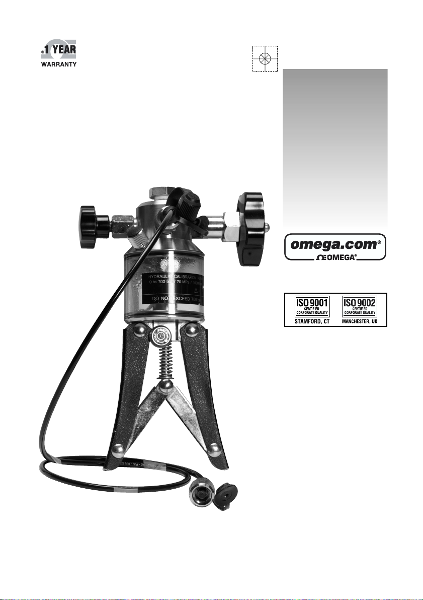
PPP-700
Hydraulic Pressure Pump
Shop online at

Servicing North America:
USA: One Omega Drive, Box 4047
ISO 9001 Certified
Stamford CT 06907-0047
Tel: (203) 359-1660 FAX: (203) 359-7700
e-mail: info@omega.com
Canada: 976 Bergar
Laval (Quebec) H7L 5A1, Canada
Tel: (514) 856-6928 FAX: (514) 856-6886
e-mail: info@omega.ca
For immediate technical or application assistance:
USA and Canada: Sales Service: 1-800-826-6342 / 1-800-TC-OMEGA
®
Customer Service: 1-800-622-2378 / 1-800-622-BEST
®
Engineering Service: 1-800-872-9436 / 1-800-USA-WHEN
®
TELEX: 996404 EASYLINK: 62968934 CABLE: OMEGA
Mexico: En Espan˜ol: (001) 203-359-7803 e-mail: espanol@omega.com
FAX: ( 001) 203-359-7807 info@omega.com.mx
Servicing Europe:
Benelux: Postbus 8034, 1180 LA Amstelveen, The Netherlands
Tel: +31 (0)20 3472121 FAX: +31 (0)20 6434643
Toll Free in Benelux: 0800 0993344
e-mail: sales@omegaeng.nl
Czech Republic: Frystatska 184/46, 733 01 Karviná, Czech Republic
Tel: +420 (0)59 6311899 FAX: +420 (0)59 6311114
Toll Free: 0800-1-66342 e-mail: info@omegashop.cz
France: 11, rue Jacques Cartier, 78280 Guyancourt, France
Tel: +33 (0)1 61 37 29 00 FAX: +33 (0)1 30 57 54 27
Toll Free in France: 0800 466 342
e-mail: sales@omega.fr
Germany/Austria: Daimlerstrasse 26, D-75392 Deckenpfronn, Germany
Tel: +49 (0)7056 9398-0 FAX: +49 (0)7056 9398-29
Toll Free in Germany: 0800 639 7678
e-mail: info@omega.de
United Kingdom: One Omega Drive, River Bend Technology Centre
ISO 9002 Certified
Northbank, Irlam, Manchester
M44 5BD United Kingdom
Tel: +44 (0)161 777 6611 FAX: +44 (0)161 777 6622
Toll Free in United Kingdom: 0800-488-488
e-mail: sales@omega.co.uk
OMEGAnet®Online Service Internet e-mail
www.omega.com info@omega.com
It is the policy of OMEGA to comply with all worldwide safety and EMC/EMI regulations that
apply. OMEGA is constantly pursuing certification of its products to the European New Approach
Directives. OMEGA will add the CE mark to every appropriate device upon certification.
The information contained in this document is believed to be correct, but OMEGA Engineering, Inc. accepts
no liability for any errors it contains, and reserves the right to alter specifications without notice.
WARNING: These products are not designed for use in, and should not be used for, human applications.

CONTENTS
1 DESCRIPTION ................................................................................. 2
1.1 Standard Accessories ........................................................................... 2
1.2 Optional Accessories ........................................................................... 2
2 OPERATION .................................................................................... 3
2.1 Reservoir Fluid Level ........................................................................... 4
3 TROUBLESHOOTING/MAINTENANCE .......................................... 5
3.1 About Bonded Seals ............................................................................. 5
3.2 Seal Replacement ................................................................................ 6
3.2.1 Main Piston Seal ....................................................................... 6
3.2.2 Fine Control Seal ...................................................................... 6
3.2.3 PPP-700 Vent Valve Seal ......................................................... 6
4 SPECIFICATIONS ............................................................................ 8
4.1 The Pump Unit ..................................................................................... 8
4.1 The Pressure Measurement Hose ....................................................... 8
5 NOTES. .......................................................................................... 10
6 WARNINGS .................................................................................... 11
(8801400) / UEPPP-700 / 010303
1

1 DESCRIPTION
The PPP-700 hydraulic pressure pump is designed to manually generate up to 700
bar (70 MPa, 10 000 psi) for quick and accurate calibration of pressure gauges,
transducers and other pressure measurement instruments.
Recommended test fluids to be used with the pump are: Low viscosity mineral
based hydraulic oils or distilled water. Do not use solvents or synthetic fluids that
will adversely affect the operation of the pump.
1.1 Standard Accessories
The standard accessories are as follows:
∗ Carrying case
∗ G 3/8 (3/8" BSP) plug to blank off the connection for an optional pressure
gauge or module.
∗ G 3/8 (3/8" BSP) to G 1/4 (1/4" BSP) adapter for connecting the optional
pressure gauge or module.
∗ A Pressure Measurement Hose for PPP-700 with two 1215 Special female
connectors.
∗ A G 1/4 (¼ BSP) male / 1215 Special male connector to connect the Pressure
Measurement Hose to the PPP-700.
∗ A 1/4" NPT male / 1215 Special male connector to connect the Pressure
Measurement Hose to the instrument to be calibrated.
∗ A filling bottle.
1.2 Optional Accessories
The optional accessories are as follows:
∗ Service kit containing a set of seals, code 8003200
∗ Relief valves for over-pressure protection
max. pressure 10 to 50 bar, code 7230600
max. pressure 50 to 200 bar, code 7231600
max. pressure 200 to 400 bar, code 7232500
max. pressure 300 to 700 bar, code 7236000
2

2 OPERATION
1. Connect the optional external pressure module or gauge to the pump (refer to the
picture on page 1) using the appropriate seals. Ensure the measurement range
of the connected module is appropriate.
2. Remove filling plug and fill reservoir with the appropriate fluid (dont exceed the
maximum level) and replace plug.
3. Connect the instrument to be tested to the Pressure Measurement Hose and
attach it to the pump. Be sure that all the output connectors are properly plugged
or connected to an instrument to avoid leakage.
4. Adjust the fine control to fully-out. Make sure the stroke selector is set to prime.
If not, squeeze handles fully in and turn the selector counterclockwise.
5. Ensure that PPP-700s vent valve is open (turn fully clockwise then one turn
counterclockwise).
6. Operate handles several times to expel air from the pump (ensure that the liquid
inlet tube remains immersed in fluid at all times).
7. Make sure no gas is left in the measurement system during the calibration procedure. Keep for example a valve connected to the measurement system open
while priming the system until all gas is removed or temporarily connect a vacuum
pump to remove gas from the measurement system. Remember to remove the
vacuum pump from the system before increasing the pressure.
8. Close PPP-700s vent valve fully clockwise.
9. Prime the system by squeezing handles together and then releasing, allowing
the fluid to enter the pump cylinder. Repeat as necessary until system is fully
primed and low pressure is indicated on either a calibrator or the test instrument.
10. Test how much pressure increase can be done using the fine control. If it is enough,
continue to step 12.
11. With handles fully squeezed in, select the high pressure position on the stroke
selector and operate handles to generate approximate pressure. The rate of the
pressure increase depends on the volume of the measurement system. Carefully
follow the reading of the pressure indicator in order to avoid exceeding the maximum pressure of the measurement system. NOTE: Smaller handle strokes enable easier pressure generation at high pressures.
12. Adjust pressure to required value using the fine control. Immediately after pressure generation, the pressure may fall slightly due to the stretching of the pressure measurement hose. Thermodynamic effects may also cause pressure variation. In that case, adjust the pressure back to required value using the fine control.
13. The principal tool for releasing pressure from the measurement system is
3
 Loading...