

Page 1
ISO 9002
CERTIFIED
CORPORATE QUALITY
MANCHESTER, UK
pH/ORP
10.20 pH
25.0 °C
User’s Guide
Shop online at
ENTER
www.omega.com
e-mail: info@omega.com
ISO 9001
CERTIFIED
CORPORATE QUALITY
STAMFORD, CT
PHTX-271 Series
pH/ORP Transmitter
Page 2

omega.com
omega.com
TM
®
OMEGAnet® Online Service Internet e-mail
www.omega.com info@omega.com
Servicing North America:
USA: One Omega Drive, P.O. Box 4047
ISO 9001 Certi ed Stamford CT 06907-0047
TEL: (203) 359-1660 FAX: (203) 359-7700
e-mail: info@omega.com
Canada: 976 Bergar
Laval (Quebec) H7L 5A1
TEL: (514) 856-6928 FAX: (514) 856-6886
e-mail: info@omega.ca
For immediate technical or application assistance:
USA and Canada: Sales Service: 1-800-826-6342 / 1-800-TC-OMEGA
Customer Service: 1-800-622-2378 / 1-800-622-BEST
Engineering Service: 1-800-872-9436 / 1-800-USA-WHEN
TELEX: 996404 EASYLINK: 62968934 CABLE: OMEGA
®
®
®
Mexico: En Español: (001) 203-359-7803 e-mail: espanol@omega.com
FAX: (001) 203-359-7807 info@omega.com.mx
Servicing Europe:
Benelux: Postbus 8034, 1180 LA Amstelveen, The Netherlands
TEL: +31 (0)20 3472121 FAX: +31 (0)20 6434643
Toll Free in Benelux: 0800 0993344
e-mail: sales@omegaeng.nl
Czech Republic: Rudé arm
TEL: +420 (0)59 6311899 FAX: +420 (0)59 6311114
Toll Free: 0800-1-66342 e-mail: info@omegashop.cz
France: 11, rue Jacques Cartier, 78280 Guyancourt, France
TEL: +33 (0)1 61 37 29 00 FAX: +33 (0)1 30 57 54 27
Toll Free in France: 0800 466 342
e-mail: sales@omega.fr
Germany/Austria: Daimlerstrasse 26, D-75392 Deckenpfronn, Germany
TEL: +49 (0)7056 9398-0 FAX: +49 (0)7056 9398-29
Toll Free in Germany: 0800 639 7678
e-mail: info@omega.de
United Kingdom: One Omega Drive, River Bend Technology Centre
ISO 9002 Certi ed Northbank, Irlam, Manchester
M44 5BD United Kingdom
TEL: +44 (0)161 777 6611 FAX: +44 (0)161 777 6622
Toll Free in United Kingdom: 0800-488-48
e-mail: sales@omega.co.uk
.
dy 1868, 733 01 Karvin. 8
It is the policy of OMEGA to comply with all worldwide safety and EMC/EMI regulations that apply. OMEGA is
constantly pursuing certi cation of its products to the European New Approach Directives. OMEGA will add the
CE mark to every appropriate device upon certi cation.
The information contained in this document is believed to be correct, but OMEGA Engineering, Inc. accepts
no liability for any errors it contains, and reserves the right to alter speci cations without notice.
WARNING: These products are not designed for use in, and should not be used for, patient-connected applications.
Page 3
Omega PHTX-271 Series pH/ORP Transmitter
pH/ORP
10.20 pH
25.0 °C
ENTER
CAUTION!
• Remove power to unit before wiring input and output connections.
• Follow instructions carefully to avoid personal injury.
Contents
1. Installation
2. Specifi cations
3. Electrical Connections
4. Menu Functions
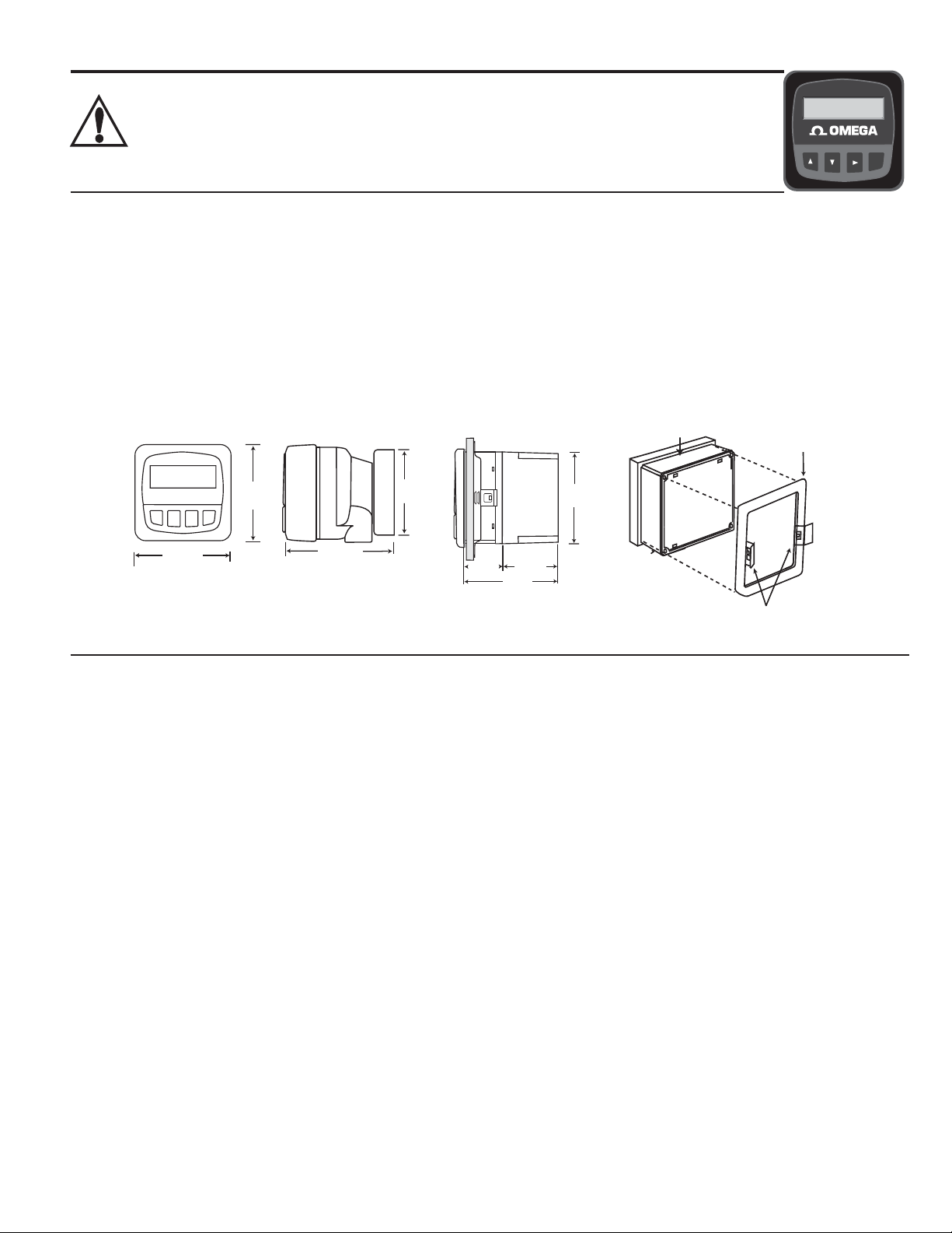
Installation
PHTX-271 series transmitters are available in two styles: panel mount and fi eld mount. The panel mount is supplied with the
necessary hardware to install the transmitter. This manual includes complete panel mounting instructions.
Field mounting requires a separate mounting kit. The FP90-UM Universal kit enables the transmitter to be installed virtually
anywhere. Detailed instructions for fi eld installation options are included with the FP90-UM Universal kit.
Panel Installation
1. The panel mount transmitter is designed for installation using a ¼ DIN Punch. For manual panel cutout, an adhesive template
is provided as an installation guide. Recommended clearance on all sides between instruments is 1 inch.
2. Place gasket on instrument, and install in panel.
3. Slide mounting bracket over back of instrument until quick-clips snap into latches on side of instrument.
4. To remove, secure instrument temporarily with tape from front or grip from rear of instrument. DO NOT RELEASE.
Press quick-clips outward and remove.
96 mm
(3.8 in.)
82 mm
(3.23 in.)
Optional
Rear
Cover
92 mm
(3.6 in.)
gasket
mounting
bracket
96 mm
(3.8 in.)
FRONT VIEW
Field &
Panel Mount
106 mm
(4.18 in.)
SIDE VIEW
Field Mount with
Universal kit
Specifi cations
General
Compatible electrodes: PH-2720-PA Preamplifi er and
PHE/ORE series electrodes
Accuracy: ± 0.03 pH, ± 2 mV ORP
Enclosure:
• Rating: NEMA 4X/IP65 front
• Case: PBT
• Panel case gasket: Neoprene
• Window: Polyurethane coated polycarbonate
• Keypad: Sealed 4-key silicone rubber
• Weight: Approx. 325g (12 oz.)
Display:
• Alphanumeric 2 x 16 LCD
• Contrast: User selected, 5 levels
• Update rate: 1 second
Electrical
• Power: 12 to 24 VDC ±5%, regulated, 21 mA max.
Sensor input range:
• pH: 0.00 to 14.00 pH
• temp. 3K Balco, -25 to 120°C (-13 to 248°F)
• ORP: -1000 to +2000 mV, isolated
(10KΩ I.D. resistance T+, T-)
Current output:
• 4 to 20 mA, isolated, fully adjustable and reversible
• Max loop impedance: 50 Ω max. @ 12 V
325 Ω max. @ 18 V
600 Ω max. @ 24 V
56 mm
41 mm
(2.2 in.)
(1.6 in.
)
97 mm
(3.8 in.)
Panel Mount with
NEMA 4X rear cover
Panel Mount
Installation Detail
quick-clips
• Update rate: 0.5 seconds
• Accuracy: ±0.03 mA @ 25°C, 24 V
Open-collector output:
• Isolated, 50 mA sink or source, 30 VDC max. pull-up voltage
• Programmable for:
• High or Low with adjustable hysteresis
• Proportional pulse (400 pulses per minute maximum)
Relay outputs (2 sets mechanical SPDT contacts):
• Maximum voltage rating: 5 A @ 30 VDC, or 5 A @ 250 VAC
resistive load
• High or Low programmable with adjustable hysteresis
• Pulse programmable (maximum 400 pulses/minute)
Environmental
• Operating temperature: -10 to 70°C (14 to 158°F)
• Storage temperature: -15 to 80°C (5 to 176°F)
• Relative humidity: 0 to 95%, non-condensing
• Maximum altitude: 2000 m (6562 ft)
• Insulation category: II
• Pollution degree: 2
Standards and Approvals
• CE
• Immunity: EN50082-2
• Emissions: EN55011
• Safety: EN61010
• Manufactured under ISO 9001 and ISO 14001
1 of 24
Page 4
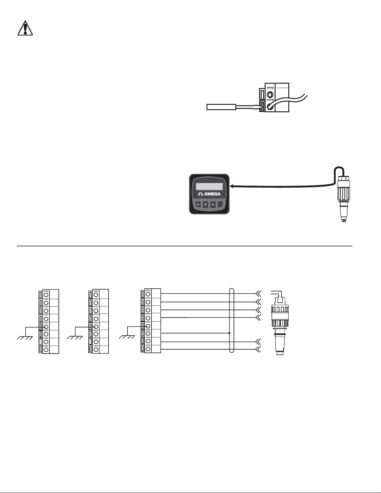
Electrical Connections
12
11
10
9
8
7
6
5
White (Temp)
Green (Temp)
Blue (ISO GND)
Brown (mV input)
Silver (Shield)
Black (V-)
Red (V+)
Preamplifier:
PH-2720-PA
pH Electrodes:
PHE series
ORP Electrodes:
ORE series
(Connecting this terminal to Earth GND
may reduce electrical interference)
18
17
16
15
14
13
12
11
16
15
14
13
12
11
10
9
***
*
PHTX-271-1
Terminals
PHTX-271-3
Terminals
PHTX-271-2
Terminals
Caution: Failure to fully open terminal jaws before
removing wire may permanently damage instrument.
Wiring Procedure
1. Remove 0.5 - 0.625 in. (13-16 mm) of insulation from wire
end.
2. Press the orange terminal lever downward with a small
screwdriver to open terminal jaws.
3. Insert exposed (non-insulated) wire end in terminal hole
until it bottoms out.
4. Release orange terminal lever to secure wire in place.
Gently pull on each wire to ensure a good connection.
Wiring Removal Procedure
1. Press the orange terminal lever downward with a small
screwdriver to open terminal jaws.
2. When fully open, remove wire from terminal.
Sensor Input Connections
Wiring Tips:
• Do not route sensor cable in conduit containing AC power
wiring. Electrical noise may interfere with sensor signal.
• Routing sensor cable in grounded metal conduit will help
prevent electrical noise and mechanical damage.
• Seal cable entry points to prevent moisture damage.
• Only one wire should be inserted into a terminal. Splice
double wires outside the terminal.
• The maximum cable length from sensor to the pH transmitter
is 400 ft. (122 m).
pH/ORP
10.20 pH
25.0 °C
2
1
ENTER
≤ 400 ft. (122 m)
ENTER
2 of 24
Page 5
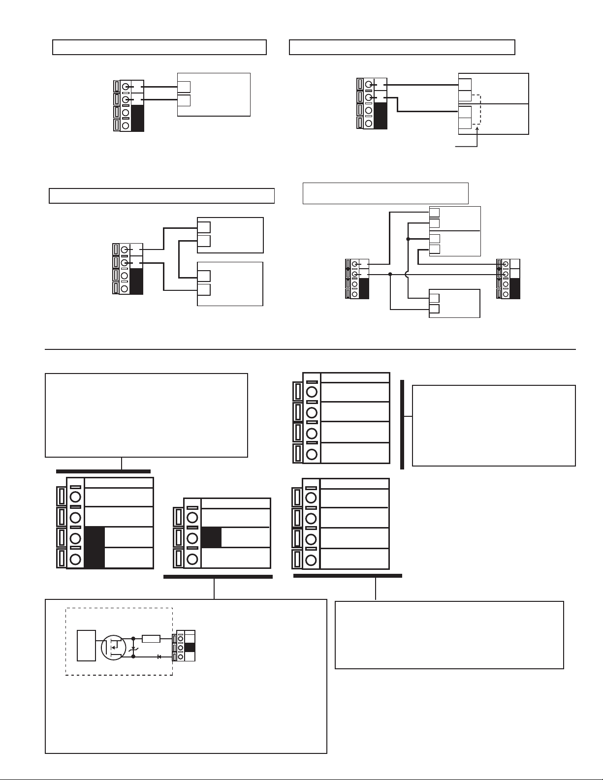
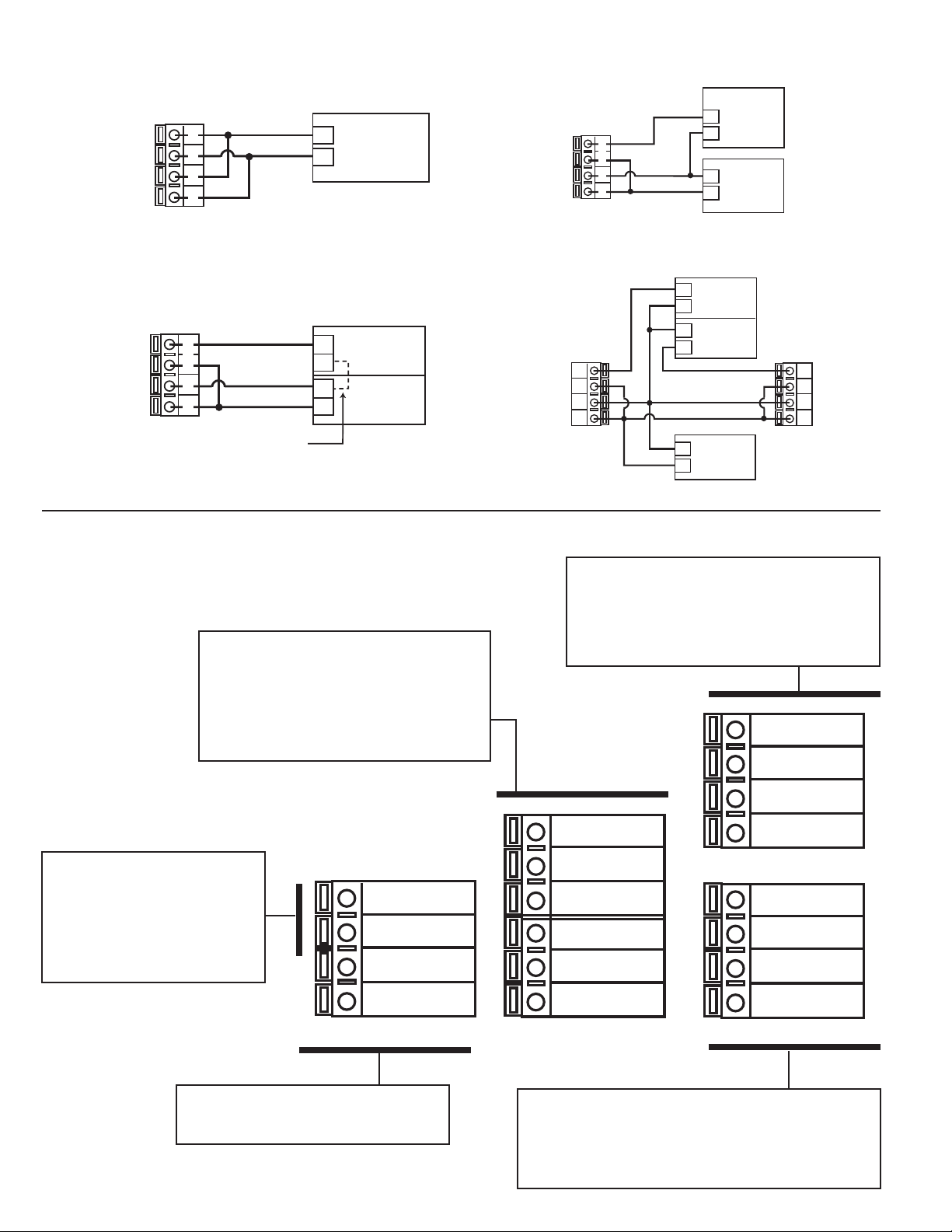
PHTX-271-1 System Power/Loop Connections
Internal open-collector
output circuit
Output --
Output +
Isolation
15Ω
S
D
Stand-alone application, no current loop used
Transmitter
Terminals
System Pwr Loop -
System Pwr Loop +
2
4
1
3
+
Power
Supply
12-24 VDC
Connection to a PLC/Recorder, separate supply
PLC or Recorder
System Pwr Loop -
System Pwr Loop +
Transmitter
Terminals
2
4
1
3
+
-
-
12-24 VDC
+
Loop Input
4-20 mA
Power
Supply
Connection to a PLC with built-in power supply
Transmitter
Terminals
System Pwr Loop -
System Pwr Loop +
Two transmitters connected to PLC/Recorder
with separate power supply
Transmitter 1
Ter min al s
System Pwr Loop -
System Pwr Loop +
2
4
1
3
Internal
PLC
Connection
2
4
1
3
+
-
+
+
+
-
+
-
Channel 1
4-20 mA in
Channel 2
4-20 mA in
Power
Supply
12-24 VDC
PLC Terminals
Loop Input
4-20 mA
Power
Supply
12-24 VDC
PLC or Recorder
Transmitter 2
Terminals
2
System Pwr Loop -
4
1
System Pwr Loop +
3
PHTX-271-1 Rear Terminals
Terminals 1 and 2: Loop Power
12-24 VDC ±10% system power and current
loop output.
Max. loop impedance:
50 Ω max. @ 12 V
325 Ω max. @ 18 V
600 Ω max. @ 24 V
System Pwr
2
Loop -
System Pwr
1
Loop +
4
3
Output -
Output +
Temp -
12
(WHITE)
11
10
9
8
7
6
5
Temp +
(GREEN)
Iso. GND
(BLUE)
mV Input
(BROWN)
Earth
GND
Sensr Gnd
(SHIELD)
V(BLACK)
V+
(RED)
Terminals 9-12: Sensor connections
• 9-10 are mV (pH or ORP) input from
the electrode.
• 11-12 are Temperature input from the
electrode
Terminals 5-8: Preamplifi er power and grounds
5-6 are DC voltages from the transmitter to power the
preamplifi er.
7-8 are ground terminals for the sensor and for earth
ground.
Terminals 3 and 4: Open-collector Output
• A transistor output, programmable in CALIBRATE menu as:
• High or Low with adjustable hysteresis
• Proportional pulse up to 400 pulses per minute
• May be disabled (Off) if not used.
3 of 24
Page 6
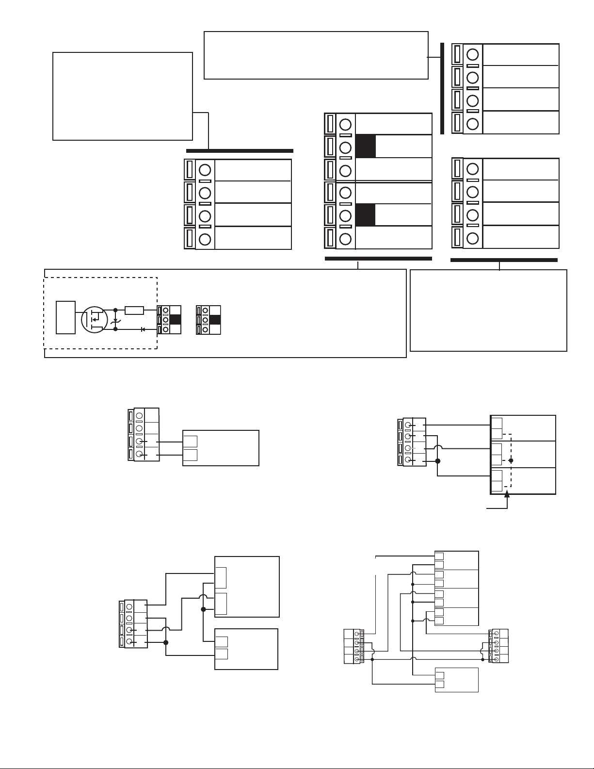
PHTX-271-2 System Power/Loop Connections
p
p
Stand-alone application, no current loop used
Transmitter
Terminals
System Pwr Loop -
System Pwr Loop +
AUX Power -
AUX Power +
4
4
3
3
2
2
1
1
+
Connection to a PLC with built-in power supply
System Pwr Loop -
System Pwr Loop +
AUX Power -
AUX Power +
Transmitter
Terminals
4
4
3
3
2
2
1
1
PLC
Internal
Connection
PLC Terminals
+
-
+
Power
Supply
12-24 VDC
Loop Input
4-20 mA
Power
Supply
12-24 VDC
Connection to a PLC/Recorder, separate supply
PLC or Recorder
Transmitter
Terminals
System Pwr Loop -
System Pwr Loop +
AUX Power -
AUX Power +
Two transmitters connected to PLC/Recorder
with separate power supply
System Pwr Loop -
System Pwr Loop +
AUX Power -
AUX Power +
4
4
3
3
2
2
1
1
Transmitter 1
Terminals
4
3
2
1
+
-
+
-
12-24 VDC
+
+
-
+
Channel 1
4-20 mA in
Channel 2
4-20 mA in
Power
Supply
Loop Input
4-20 mA
Power
Supply
12-24 VDC
PLC or Recorder
Transmitter 2
Terminals
4
System Pwr Loo
4
3
System Pwr Loo
3
2
AUX Power -
2
1
AUX Power +
1
PHTX-271-2 Rear Terminals
Terminals 5-10: Relay Outputs
Two sets mechanical SPDT contacts,
programmable (see CALIBRATE menu) as:
• High or Low with adjustable hysteresis
• proportional pulse based on pH or ORP
• May be disabled (Off) if not used.
Terminals 3 and 4: Loop Power
12-24 VDC ±10% system power
and current loop output.
Max. loop impedance:
50 Ω max. @ 12 V
325 Ω max. @ 18 V
600 Ω max. @ 24 V
System Pwr
4
Loop -
System Pwr
3
Loop +
AUX
2
Power -
AUX
Power +
1
Terminals 15-18: Sensor connections
• 15-16 are mV (pH or ORP) input from
the electrode.
• 17-18 are temperature input from the
pH electrode or10KΩ identifying resistor
from the ORP electrode.
18
17
16
Relay 2
10
9
8
7
6
5
(NO)
Relay 2
(COM)
Relay 2
(NC)
Relay 1
(NO)
Relay 1
(COM)
Relay 1
(NC)
15
14
13
12
11
Temp (WHITE)
Temp +
(GREEN)
Iso. GND
(BLUE)
mV Input
(BROWN)
Earth
GND
Sensr Gnd
(SHIELD)
V(BLACK)
V+
(RED)
4 of 24
Terminals 1 and 2: AUXILIARY power
Provides power for relay operation.
Terminals 11-14: Preamplifi er power and grounds
• 11-12 are DC voltages from the transmitter to power
the preamplifi er.
• 13-14 are ground terminals for the sensor and for
earth ground
Page 7
PHTX-271-3 Rear Terminals
Terminals 1-4: Loop Power
12-24 VDC ±10% system power
and current loop output.
Max. loop impedance:
50 Ω max. @ 12 V
325 Ω max. @ 18 V
600 Ω max. @ 24 V
Terminals 13-16: Sensor connections
13-14 are mV (pH or ORP) input from the electrode.
15-16 are Temperature input from the pH electrode or
10K Ω id resistor from ORP electrode
Output 2-
8
16
15
14
13
Temp (WHITE)
Temp +
(GREEN)
Iso. GND
(BLUE)
mV Input
(BROWN)
4
3
2
1
Internal open-collector
output circuit
15W
S
Isolation
D
PHTX-271-3 System Power/Loop Connections
Stand-alone application, no current loop used
Loop 2 -
Loop 2 +
System Power Loop 1 -
System Power Loop 1 +
Transmitter Terminals
Outputs
1
2
_
+
NC
4
NC
3
2
1
_
+
Power
Supply
12-24 VDC
Loop 2 -
Loop 2 +
System Pwr
Loop 1 -
System Pwr
Loop 1 +
7
6
5
Output 2+
Output 1-
Output 1+
Terminals 5-8: Open-collector Outputs
Two transistor outputs, programmable in
CALIBRATE menu as:
• High or Low with adjustable
hysteresis
• Proportional pulse up to 400 pulses
per minute
• May be disabled (Off) if not used.
Connection to a PLC with built-in power supply
Loop 2 -
Loop 2 +
System Power Loop 1 -
System Power Loop 1 +
12
11
10
9
Terminals 9-12: Preamplifi er
power and grounds
• 9-10 are DC voltages from the
8750 to power the preamplifi er.
• 11-12 are ground terminals for
the sensor and for earth ground.
Transmitter
Ter mina ls
4
3
2
1
Internal
PLC Connection
PLC Terminals
+
_
+
_
+
_
Earth
GND
Sensr Gnd
(SHIELD)
V(BLACK)
V+
(RED)
Channel 2
4-20 mA
Channel 1
4-20 mA
Power
Supply
12-24 VDC
Connection to a PLC/Recorder separate supply
PLC or Recorder
+
Channel 2
Transmitter
Ter mina ls
Loop 2 -
Loop 2 +
System Power Loop 1 -
System Power Loop 1 +
4
3
2
1
_
+
_
_
+
4-20 mA
Channel 1
4-20 mA
Power
Supply
12-24 VDC
The current loop is a passive circuit.
12-24 VDC must be provided from an external source.
Two transmitters connected to
PLC/Recorder
with separate power supply
Transmitter 1
Ter min als
Loop 2 -
4
Loop 2 +
System Power Loop 1 -
System Power Loop 1 +
3
2
1
PLC or Recorder
+
Channel 1
_
4-20 mA
+
Channel 2
_
4-20 mA
+
Channel 3
_
4-20 mA
+
Channel 4
_
4-20 mA
Power
_
Supply
+
12-24 VDC
Transmitter 2
Ter min als
4
3
2
1
Loop 2 -
Loop 2 +
System Power Loop 1 -
System Power Loop 1 +
5 of 24
Page 8
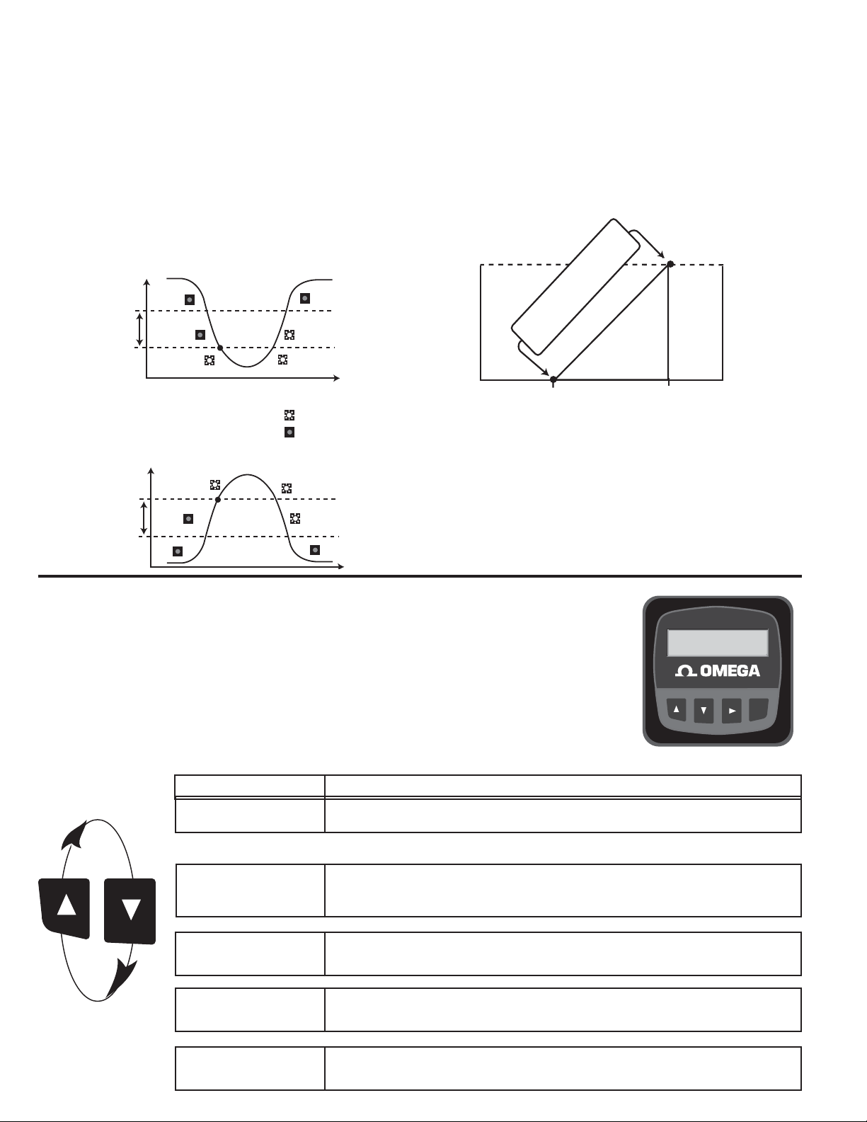
Open Collector and Relay Outputs
Hysteresis
Time
Low Setpoint
Process
Hysteresis
Output active
Output inactive
High Setpoint
Process
10
5
Open collector or Relay Output
PlsRate: 0 to 100 Pulses/min.
endpoint
Pulse rate
0 pulses
100 pulses
Starting point
Open Collector or Relay Output
pH/ORP
10.20 pH
25.0 °C
ENTER
The Open Collector and relay outputs can be used as a switch
that responds when the process value moves above or below a
setpoint, or they can be used to generate a pulsing signal with a
rate proportional to the process value.
• Low:
Output triggers when process variable is less than the setpoint.
The output will relax when the process moves above the setpoint
plus the hysteresis value.
• High:
Output triggers when process variable is greater than the
setpoint. The output will relax when the process moves below the
setpoint plus the hysteresis value.
• Proportional Pulsing
The output will generate a 100 mS pulse at the rate defi ned by
settings in the CALIBRATE menu (see page 6)
In the example below:
• The output will be 0 pulses/min. at pH values less than 5.0.
• The output will be 50 pulses/min. at 7.5 pH.
• The output will be 100 pulses/min. at pH values above 10 pH.
VIEW menu
• During normal operation, the transmitter displays the VIEW menu.
• When using the CALIBRATE or OPTIONS menus, the transmitter will return to the VIEW menu if no
activity occurs for 10 minutes.
• To select the item you want displayed, press the UP or DOWN arrow keys. The items will scroll in a
continuous loop. Changing the display selection does not interrupt system operations.
• No key code is necessary to change display selection.
• Output settings cannot be edited from the VIEW menu.
View Menu for PHTX-271 Series
Display Description
Monitor the Temperature input from the sensor.
This is the Permanent display.
Monitor the millivolt input from the electrode. Use this display to determine the
relative condition of your electrode during periodic calibration. (7 pH buffer = 0
mV, ±50 mV)
Monitor the 4-20 mA Loop output.
Monitor date for scheduled maintenance or date of last calibration.
Easy Cal is the fastest and simplest periodic calibration method. Requires 4 pH,
7 pH and 10 pH. (Any two)
6 of 24
7.00 pH
12.6 °C
All of the VIEW displays below are temporary. The permanent display will return after ten minutes.
Input:
307 mV
Loop Output:
14.16 mA
Last CAL:
6-30-00 >
EASY
CAL: >
Page 9
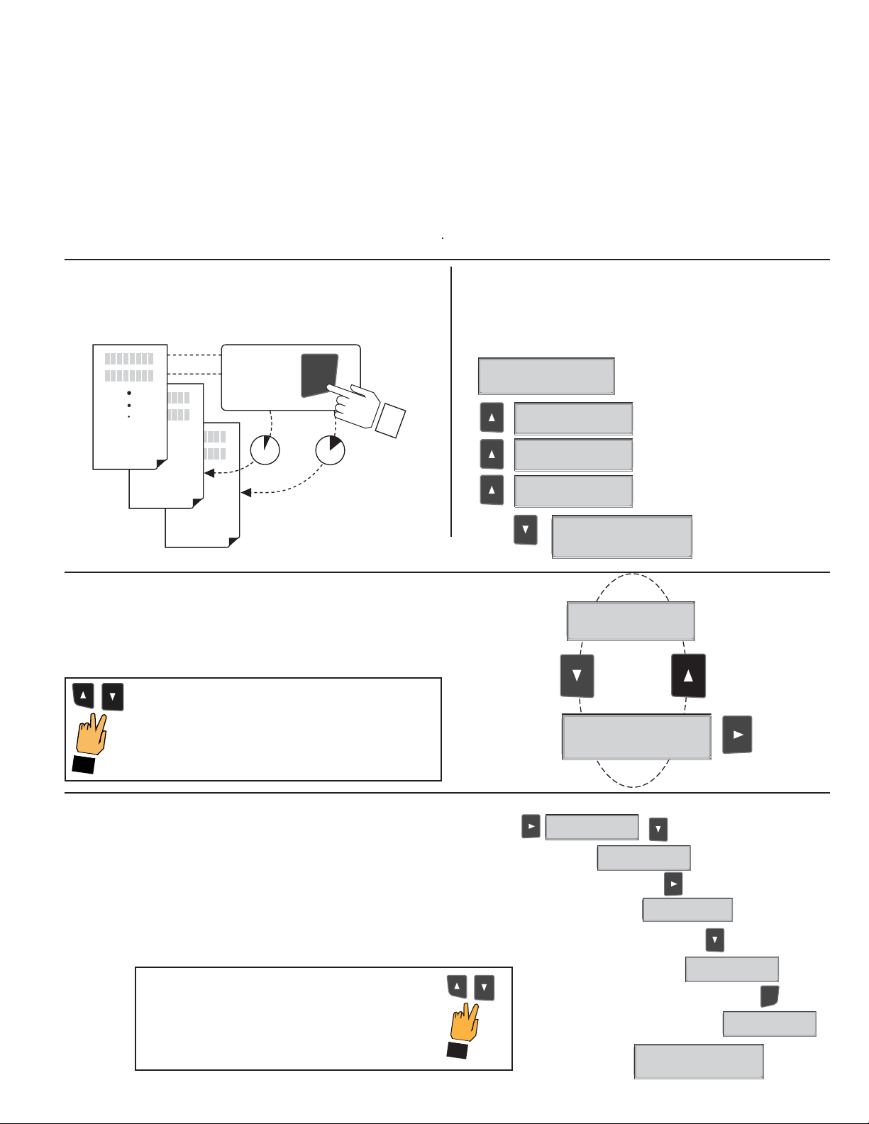
PHTX-271 Editing Procedure:
OPTIONS
CALIBRATE
VIEW
2s 5s
Press &
hold for
access:
ENTER
Step 1. Press and hold ENTER key:
• 2 seconds to select the CALIBRATE menu
• 5 seconds to select the OPTIONS menu.
Step 2. The Key Code is UP-UP-UP-DOWN keys in sequence.
• After entering the Key Code, the display will show the fi rst item in the selected menu.
Step 3. Scroll menu with UP or DOWN arrow keys.
Step 4. Press RIGHT ARROW key to select menu item to be edited.
• The fi rst display element will begin fl ashing.
Step 5. Press UP or DOWN keys to edit the fl ashing element.
• RIGHT ARROW key advances the fl ashing element.
Step 6. Press ENTER key to save the new setting and return to Step 3.
Notes on Step 1:
• The View Menu is normally displayed.
• The CALIBRATE and OPTIONS menus require a KEY CODE.
Notes on Step 2:
If no key is pressed for 5 minutes while display is showing "Enter
Key Code", the display will return to the VIEW menu.
CALIBRATE: ----
Enter Key Code
Notes on Steps 3 and 4:
• Refer to pages 6 and 7 for complete listing of menu items and their use.
• From the Step 3 display, pressing the UP and DOWN keys simultaneously will
return the display to the VIEW menu.
• If no key is pressed for 10 minutes, display will also return to the VIEW menu.
CALIBRATE: *---
Enter Key Code
CALIBRATE: **--
Enter Key Code
CALIBRATE: ***-
Enter Key Code
Set:
Temperature >
Temperature >
First item in
CALIBRATE menu
Set:
Step 3
Step 3: Finished Editing?
Press the UP and DOWN keys simultaneously after
saving the last setting to return to normal operation.
Notes on Steps 5 and 6:
• All output functions remain active during editing.
• Only the fl ashing element can be edited.
• RIGHT ARROW key advances the fl ashing element in a continuous loop.
• Edited value is effective immediately after pressing ENTER key.
• If no key is pressed for 10 minutes unit will restore the last saved value and return to step 3.
• Step 6 (pressing ENTER key) always returns you to Step 3.
• Repeat steps 3-6 until all editing is completed.
Step 5: Made an Error?
Press the UP and DOWN keys simultaneously
while any element is fl ashing. This will recall the
last saved value of the item being edited and
return you to Step 3.
Output Setpnt:
10.0 pH >
Output Setpnt:
10.00 pH
Output Setpnt:
00.00 pH
Output Setpnt:
0.00 pH
0
Step 6
Output Setpnt:
9.00 pH >
Step 5
Output Setpnt:
9
.00 pH
0
Output Setpnt:
Saving
Step 4
ENTER
7 of 24
Page 10

Calibrate Menu for PHTX-271-1 pH
Display
(Factory settings shown)
Description
Set:
Temperature >
Provides a maximum 25ºC offset to match temperature measurement to external reference.
Set:
Standard >
Set:
Slope >
Applies a linear offset to the pH measurement. If you are using a single-point calibration,
use this function. The ideal value is the average pH of your application. (A sample of your
application at process temperature is recommended.)
Applies a slope to the pH measurement. This function should only be used in a two-point
calibration. The slope value and the standard value must be at least 2 pH units apart.
The ideal values are the minimum and maximum values of your process.
Loop Range: pH
Select the minimum and maximum values for the 4-20 mA Current loop output.
0.00 → 14.00 >
Output Source:
pH >
Select pH or Temperature as the source for the Open Collector Output.
Output Mode:
Select the mode of operation for the Open Collector output: High, Low or proportional Pulse.
The signal may be disabled if not in use.
Low >
Output Setpnt:
4.00 pH >
In Low or High Mode, the Open Collector output will be activated when the pH reaches this
value.
Output Hys:
In Low or High mode, the Open Collector output will be deactivated at Setpoint ± Hysteresis,
depending on High or Low Setpoint selection. (See details on page 4.)
0.50 pH >
Output Range: pH
In Pulse mode, set the pH values for zero and for maximum pulse rate.
4.00 → 8.00 >
Output PlsRate:
In Pulse mode, set the maximum pulse rate, up to 400 pulses per minute.
120 Pulses/min >
Last CAL:
6-30-01 >
Use this “note pad” to record important dates, such as annual recertifi cation or scheduled
maintenance.
8 of 24
Page 11

Options Menu for PHTX-271-1 pH
Display
(Factory settings shown)
Contrast:
3 >
Averaging:
O >
Output Active:
Low >
Adjust the LCD contrast for best viewing. A setting of 1 is lower contrast, 5 is higher.
Select lower contrast if the display is in warmer ambient surroundings.
OFF provides the most instantaneous output response to changes in input value.
LOW averaging = 4 seconds, HIGH averaging = 8 seconds of input signal.
Active HIGH: This setting is used to turn a device (pump, valve) ON at the setpoint.
Active LOW: This setting is used to turn a device (pump, valve) OFF at the setpoint.
Temp Display:
°C >
Loop Adjust:
4.00 mA >
Loop Adjust:
20.00 mA >
Select temperature units: ºC or ºF.
Adjust the minimum and maximum current output. The display value represents the
precise current output.
Adjustment limits:
• 3.80 mA < 4.00 mA > 5.00 mA
• 19.00 mA < 20.00 mA > 21.00 ma
Use this setting to match the PHTX-271 loop current to any external device.
Test Loop:
>
Test Output:
Press UP or DOWN keys to manually order any output current value from 3.6 mA to 21.00
mA to test current loop output.
Press UP or DOWN keys to manually toggle the state of the open collector output.
>
Description
9 of 24
Page 12

Calibrate Menu for PHTX-271-1 ORP
Display
(Factory settings shown)
Description
Set:
Standard >
Set:
Slope >
Loop Range: mV
-1000 → +1000 >
Output Mode:
Applies a linear offset to the ORP measurement. If you are using a single-point calibration,
use this function. The ideal value is the average pH of your application. (A sample of your
application at process temperature is recommended.)
Applies a slope to the ORP measurement. This function should only be used in a two-point
calibration. The slope value and the standard value must be at least 2 pH units apart. The
ideal values are the minimum and maximum values of your application.
Select the minimum and maximum ORP values for the 4-20 mA Current loop output.
Maximum settings are -1000 mV to +2000 mV.
Select the desired mode of operation for the Open Collector output: High, Low or
proportional Pulse. The signal may also be disabled if not in use.
O >
Output Setpnt:
-500 mV >
Output Hys:
10 mV >
Output Range: mV
-500 → +500 >
In Low or High Mode, the Open Collector output will be deactivated when the ORP reaches
this value.
In Low or High mode, the Open Collector output will be deactivated at Setpoint ± Hysteresis,
depending on High or Low Setpoint selection. (See details on page 4.)
In Pulse mode, set the ORP values for zero and for maximum pulse rate.
Output PlsRate:
120 pulses/min >
Last Cal:
6-30-01 >
In Pulse mode, set the maximum pulse rate, up to 400 pulses per minute.
Use this “note pad” to record important dates, such as annual recertifi cation or scheduled
maintenance.
10 of 24
Page 13

Options Menu for PHTX-271-1 ORP
Display
(Factory settings shown)
Contrast:
3 >
Averaging:
O >
Output1 Active:
Low >
Adjust the LCD contrast for best viewing. A setting of 1 is lower contrast, 5 is higher.
Select lower contrast if the display is in warmer ambient surroundings.
OFF provides the most instantaneous output response to changes in input value.
LOW averaging = 4 seconds, HIGH averaging = 8 seconds of input signal.
Longer averaging produces more stable display and output response.
Active HIGH: This setting is used to turn a device (pump, valve) ON at the setpoint.
Active LOW: This setting is used to turn a device OFF at the setpoint.
Loop 1 Adjust:
4.00 mA >
Loop 1 Adjust:
20.00 mA >
Adjust the minimum and maximum current output. The display value represents the
precise current output.
Adjustment limits:
• 3.80 mA < 4.00 mA > 5.00 mA
• 19.00 mA < 20.00 mA > 21.00 ma
Use this setting to match thePHTX-271 loop current to any external device.
Description
Test Loop1:
>
Test Output1:
Press UP or DOWN keys to manually order any output current value from 3.6 mA to
21.00 mA to test current loop output.
Press UP or DOWN keys to manually toggle the state of the open collector output.
>
All Loop1 and Output1 functions will repeat for Loop2 and Output2.
11 of 24
Page 14

Calibrate Menu for PHTX-271-2 pH
Display
(Factory settings shown)
Set:
Temperature >
Set:
Standard >
Set:
Slope >
Loop Range: pH
0.00 → 14.00 >
Provides a maximum 25ºC offset to match temperature measurement to external reference.
Applies a linear offset to the pH measurement. If you are using a single-point calibration,
use this function. The ideal value is the average pH of your application. (A sample of your
application at process temperature is recommended.)
Applies a slope to the pH measurement. This function should only be used in a two-point
calibration. The slope value and the standard value must be at least 2 pH units apart.
The ideal values are the minimum and maximum values of your process.
Select the minimum and maximum values for the 4-20 mA Current loop output.
Description
Relay1 Source:
pH >
Select pH or Temperature as the source for this relay.
Relay1 Mode:
O >
Relay1 Setpnt:
4.00 pH >
Relay1 Hys:
0.51 pH >
Relay1 Range:
Select the mode of operation for this relay: High, Low or proportional Pulse.
The signal may be disabled if not in use.
In Low or High Mode, the relay will be activated when the pH reaches this value.
In Low or High mode, the relay will be deactivated at Setpoint ± Hysteresis, depending on
High or Low Setpoint selection. (See details on page 4.)
In Pulse mode, set the ph values for zero and for maximum pulse rate.
4.00 → 8.00 >
Relay1 Plsrate:
In Pulse mode, set the maximum pulse rate, up to 400 pulses per minute.
120 Pulses/min >
Last CAL:
6-30-01 >
Use this “note pad” to record important dates, such as annual recertifi cation or scheduled
maintenance.
All Relay1 functions will repeat for Relay2.
12 of 24
Page 15

Options Menu for PHTX-271-2 pH
Display
(Factory settings shown)
Contrast:
3 >
Averaging:
O >
Temp Display:
°C >
Loop Adjust:
4.00 mA
Loop Adjust:
20.00 mA >
Adjust the LCD contrast for best viewing. A setting of 1 is lower contrast, 5 is higher.
Select lower contrast if the display is in warmer ambient surroundings.
OFF provides the most instantaneous output response to changes in input value.
LOW averaging = 4 seconds, HIGH averaging = 8 seconds of input signal.
Select temperature units: ºC or ºF.
Adjust the minimum and maximum current output. The display value represents the
precise current output.
Adjustment limits:
• 3.80 mA < 4.00 mA > 5.00 mA
• 19.00 mA < 20.00 mA > 21.00 ma
Use this setting to match the PHTX-271 loop current to any external device.
Test Loop:
>
Test Relay 1:
>
Test Relay 2:
Press UP or DOWN keys to manually order any output current value from 3.6 mA to
21.00 mA to test current loop output.
Press UP or DOWN keys to manually toggle the state of the open collector output.
Press UP or DOWN keys to manually toggle the state of the open collector output.
>
All Relay1 functions will repeat for Relay2.
Description
13 of 24
Page 16

Calibrate Menu for PHTX-271-2 ORP
Display
(Factory settings shown)
Description
Set:
Standard >
Set:
Slope >
Loop Range: mV
-1000 > +1000 >
Relay1 Mode:
O >
Relay1 Setpnt:
-500 mV >
Relay1 Hys:
10 mV >
Relay1 Range: mV
-500 → +500 >
Applies a linear offset to the ORP measurement. If you are using a single-point calibration,
use this function. The ideal value is the average pH of your application. (A sample of your
application at process temperature is recommended.)
Applies a slope to the ORP measurement. This function should only be used in a two-point
calibration. The slope value and the standard value must be at least 2 pH units apart. The
ideal values are the minimum and maximum values of your application.
Select the minimum and maximum ORP values for the 4-20 mA Current loop output.
Maximum settings are -1000 mV to +2000 mV.
Select the mode of operation for this relay: High, Low or proportional Pulse.
The signal may also be disabled if not in use.
In Low or High Mode, the relay will be activated when the ORP reaches this value.
In Low or High mode, the relay will be deactivated at Setpoint ± Hysteresis, depending on
High or Low Setpoint selection. (See details on page 4.)
In Pulse mode, set the ORP values for zero and for maximum pulse rate.
Relay1 PlsRate:
120 pulses/min >
Last Cal:
6-30-01 >
All Relay1 functions will repeat for Relay2.
In Pulse mode, set the maximum pulse rate, up to 400 pulses per minute.
Use this “note pad” to record important dates, such as annual recertifi cation or scheduled
maintenance.
14 of 24
Page 17

Options Menu for PHTX-271-2 ORP
Display
(Factory settings shown)
Contrast:
3 >
Averaging:
O >
Adjust the LCD contrast for best viewing. A setting of 1 is lower contrast, 5 is higher.
Select lower contrast if the display is in warmer ambient surroundings.
OFF provides the most instantaneous output response to changes in input value.
LOW averaging = 4 seconds, HIGH averaging = 8 seconds of input signal.
Longer averaging produces more stable display and output response.
Loop Adjust:
4.00 mA >
Loop Adjust:
20.00 mA >
Adjust the minimum and maximum current output. The display value represents the
precise current output.
Adjustment limits:
• 3.80 mA < 4.00 mA > 5.00 mA
• 19.00 mA < 20.00 mA > 21.00 ma
Use this setting to match the PHTX-271 loop current to any external device.
Test Loop:
Press UP or DOWN keys to manually order any output current value from 3.6 mA to
21.00 mA to test current loop output.
>
Description
Test Relay 1:
Press UP or DOWN keys to manually toggle the state of the relay.
>
Test Relay 2:
>
All Relay1 functions will repeat for Relay2.
Press UP or DOWN keys to manually toggle the state of the relay.
15 of 24
Page 18

Calibrate Menu for PHTX-271-3 pH
Display
(Factory settings shown)
Set:
Temperature >
Set:
Standard >
Set:
Slope >
Loop1 Range: pH
0.00 → 14.00 >
Provides a maximum 25ºC offset to match temperature measurement to external reference.
Applies a linear offset to the pH measurement. If you are using a single-point calibration,
use this function. The ideal value is the average pH of your application. (A sample of your
application at process temperature is recommended.)
Applies a slope to the pH measurement. This function should only be used in a two-point
calibration. The slope value and the standard value must be at least 2 pH units apart.
The ideal values are the minimum and maximum values of your process.
Select the minimum and maximum values for the 4-20 mA Current loop output.
Description
Output1 Source:
pH >
Output1 Mode:
Low >
Output1 Setpnt:
4.00 pH >
Output1 Hys:
0.50 pH >
Output1 Range:
Select pH or Temperature as the source for the Open Collector Output.
Select the mode of operation for the Open Collector output: High, Low or proportional Pulse.
The signal may be disabled if not in use.
In Low or High Mode, the Open Collector output will be activated when the pH reaches this
value.
In Low or High mode, the Open Collector output will be deactivated at Setpoint ± Hysteresis,
depending on High or Low Setpoint selection. (See details on page 4.)
In Pulse mode, set the pH values for zero and for maximum pulse rate.
4.00 → 8.00 >
Output1 PlsRate:
In Pulse mode, set the maximum pulse rate, up to 400 pulses per minute.
120 Pulses/min >
Last CAL:
6-30-01 >
Use this “note pad” to record important dates, such as annual recertifi cation or scheduled
maintenance.
All Loop1 and Output1 functions will repeat for Loop2 and Output2.
16 of 24
Page 19

Options Menu for PHTX-271-3 pH
Display
(Factory settings shown)
Contrast:
3 >
Averaging:
O >
Output1 Active:
Low >
Temp Display:
°C >
Loop1 Adjust:
4.00 mA >
Loop1 Adjust:
20.00 mA >
Adjust the LCD contrast for best viewing. A setting of 1 is lower contrast, 5 is higher.
Select lower contrast if the display is in warmer ambient surroundings.
OFF provides the most instantaneous output response to changes in input value.
LOW averaging = 4 seconds, HIGH averaging = 8 seconds of input signal.
Active HIGH: This setting is used to turn a device (pump, valve) ON at the setpoint.
Active LOW: This setting is used to turn a device (pump, valve) OFF at the setpoint.
Select temperature units: ºC or ºF.
Adjust the minimum and maximum current output. The display value represents the
precise current output.
Adjustment limits:
• 3.80 mA < 4.00 mA > 5.00 mA
• 19.00 mA < 20.00 mA > 21.00 mA
Use this setting to match the PHTX-271 loop current to any external device.
Test Loop1:
>
Test Output1:
>
Press UP or DOWN keys to manually order any output current value from 3.6 mA to 21.00
mA to test current loop output.
Press UP or DOWN keys to manually toggle the state of the open collector output.
Description
All Output1 and Loop1 functions will repeat for output 2 and loop 2.
17 of 24
Page 20

Calibrate Menu for PHTX-271-3 ORP
Display
(Factory settings shown)
Description
Set:
Standard >
Set:
Slope >
Loop Range: mV
-1000 → +1000 >
Output1 Mode:
O >
Output1 Setpnt:
-500 mV >
Output1 Hys:
Applies a linear offset to the ORP measurement. If you are using a single-point calibration,
use this function. The ideal value is the average pH of your application. (A sample of your
application at process temperature is recommended.)
Applies a slope to the ORP measurement. This function should only be used in a two-point
calibration. The slope value and the standard value must be at least 2 pH units apart. The
ideal values are the minimum and maximum values of your application.
Select the minimum and maximum ORP values for the 4-20 mA Current loop output.
Maximum settings are -1000 mV to +2000 mV.
Select the mode of operation for the Open Collector output: High, Low or proportional
Pulse.
The signal may also be disabled if not in use.
In Low or High Mode, the Open Collector output will be activated when the ORP reaches
this value.
In Low or High mode, the Open Collector output will be deactivated at Setpoint ±
Hysteresis, depending on High or Low Setpoint selection. (See details on page 4.)
10 mV >
Output1 Range: mV
In Pulse mode, set the ORP values for zero and for maximum pulse rate.
-500 → +500 >
Output1 PlsRate:
120 pulses/min >
In Pulse mode, set the maximum pulse rate, up to 400 pulses per minute.
Last Cal:
6-30-01 >
All Loop1 and Output1 functions will repeat for Loop2 and Output2.
Use this “note pad” to record important dates, such as annual recertifi cation or scheduled
maintenance.
18 of 24
Page 21

Options Menu for PHTX-271-3 ORP
Display
(Factory settings shown)
Contrast:
Adjust the LCD contrast for best viewing. A setting of 1 is lower contrast, 5 is higher.
Select lower contrast if the display is in warmer ambient surroundings.
3 >
Averaging:
OFF provides the most instantaneous output response to changes in input value.
O >
LOW averaging = 4 seconds, HIGH averaging = 8 seconds of input signal.
Longer averaging produces more stable display and output response.
Output1 Active:
Active HIGH: This setting is used to turn a device (pump, valve) ON at the setpoint.
Low >
Active LOW: This setting is used to turn a device OFF at the setpoint.
Loop 1 Adjust:
4.00 mA >
Loop 1 Adjust:
20.00 mA >
Adjust the minimum and maximum current output. The display value represents the
precise current output.
Adjustment limits:
• 3.80 mA < 4.00 mA > 5.00 mA
• 19.00 mA < 20.00 mA > 21.00 mA
Use this setting to match the PHTX-271 loop current to any external device.
Description
Test Loop1:
>
Press UP or DOWN keys to manually order any output current value from 3.6 mA to
21.00 mA to test current loop output.
Test Output1:
Press UP or DOWN keys to manually toggle the state of the open collector output.
>
All Loop1 and Output1 functions will repeat for Loop2 and Output2.
19 of 24
Page 22

EASY CAL Procedure - pH
• This procedure simplifi es system calibration using standard 4.0, 7.0, 10.0 pH buffers. If these pH buffer values are not available,
calibrate the system via the CALIBRATE menu, using the STANDARD and SLOPE settings.
• Access the CALIBRATE menu and set sensor temperature before performing EASY CAL for new electrode installations.
• Access EASY CAL menu from the view menu.
EASY CAL: ----
Enter Key Code
Press UP, UP, UP, DOWN buttons in sequence to enter menu,
_ _ _ _
XXXX will appear during code entry.
To Calibrate:
Place Sensor in
pH Buffer #1
Place electrode tip in
first pH buffer
pH 7.0 = 0 mV
pH 4.0 = 177
pH 10 = -177
Limit ± 50 mV
Place Sensor in
pH Buffer #2
Place electrode tip
in second pH buffer.
1
2
To exit menus and return to
VIEW press UP and DOWN
button at the same time
Response:
* 6.90 pH
-005 mV
Allow for stabilization
30 seconds*
* 3.93 pH
+179 mV
Allow for stabilization
30 seconds*
Display returns to VIEW
Menu in 10 minutes or
when ENTER is pressed
To Accept:
* 6.90 pH
-005 mV
ENTER
to accept
* 7.00 pH
-005 mV
* 3.93 pH
+179 mV
ENTER
Press to accept
second buffer calibration.
* 4.00 pH
+179 mV
Good Easy Cal
Press <ENTER>
*
For best results, gently stir the
submerged electrode for approximately
5 seconds during the stabilization
period.
Large temperature differences from
process fl uids to buffers may require
longer stabilization time.
Theoretical mV values
pH @ 25°C mV
2 +296
3 +237
4 +177
5 +118
6 +59
7 +0
8 -59
9 -118
10 -177
11 -237
12 -296
EASY CAL Procedure - ORP
• This procedure simplifi es system calibration using standard 4.0 pH and 7.0 pH buffers saturated with Quinhydrone. To calibrate
using any other ORP buffer solutions, use the Standard and Slope functions in the CALIBRATE menu.
• Access EASY CAL menu from the view menu.
EASY CAL: ----
Enter Key Code
To Calibrate:
Place Sensor in
ORP Buffer #1
Place electrode tip
in first pH buffer;
pH 7.0 ≈ 87 mV
pH 4.0 ≈ 264 mV
Place Sensor in
ORP Buffer #2
Place electrode tip
in second (different)
pH buffer.
pH 4.0 ≈ 264 mV
pH 7.0 ≈ 87 mV
To exit menus and return to
VIEW press UP and DOWN
button at the same time
Press UP, UP, UP, DOWN buttons in sequence to enter menu,
* * * * will appear during code entry.
Response:
* ORP: + 84 mV
Input: + 82 mV
Allow for stabilization to accept
1
* ORP: + 84 mV
Input: + 82 mV
ENTER
* ORP: + 87 mV
Input: + 82 mV
30 seconds*
* ORP: +262 mV
Input: +260 mV
2
Allow for stabilization
30 seconds*
* ORP: +262 mV
Input: +260 mV
Press to accept
second buffer calibration.
* ORP: +264 mV
Input: +260 mV
Display returns to VIEW
Menu in 10 minutes or
when ENTER is pressed
To Accept:
ENTER
Good Easy Cal
Press <ENTER>
*
For best results, gently stir the
submerged electrode for approximately
5 seconds during the stabilization
period.
Large temperature differences from pro-
cess fl uids to buffers may require longer
stabilization time.
Technical notes:
The difference between the actual mV and
value shown is a good indication of the
condition of the electrode.
Differences in excess of 50 mV may indicate a need to service the electrode.
20 of 24
Page 23

Troubleshooting - pH
Display Condition Possible causes
During EasyCal:
"Out of Range
Use Manual CAL"
During EasyCal:
"Same Buffer"
During CALIBRATE Std:
"Standard too close to Slope!"
During CALIBRATE Slope:
"Slope too close to Standard!"
During CALIBRATE:
"Out of Range
Check Sensor"
1. Required 4, 7 or 10 buffers not being
used.
2. Sensor is depleted too severely to
use EasyCal
Sensor was not moved from buffer #1 to
buffer #2.
1. pH Standard value within 2 pH units
of Slope value
2. pH Sensor effi ciency is inadequate
1. pH Slope value within 2 pH units of
Standard value
2. pH Sensor effi ciency is inadequate
1. No temperature or mV signal from
sensor detected.
2. No connection between pH sensor
and preamplifi er.
Suggested Solutions
1. Use pH 4, 7, 10 buffers
2. Clean probe and retry EASY CAL.
3. Use Manual calibration for Standard and
Slope if mV offset exceeds 50 mV.
1. Place sensor in correct buffer solution.
2. Use fresh buffer.
1. Use pH values at least 2 pH units apart.
2. Clean pH sensor; replace if necessary
3. Use fresh buffer.
1. Use pH values at least 2 pH units apart.
2. Clean pH sensor; replace if necessary
3. Use fresh buffer.
1. Check all wiring, contacts in preamplifi er.
2. Verify sensor is securely installed.
3. Replace pH sensor.
During normal operation:
Constant "15.00 pH"
or
constant "0.00 pH"
with good temp value
During normal operation:
"Check Sensor?"
The mV value from the sensor when placed in a 7 pH buffer represents the sensor offset. It is recommended that the sensor be
serviced and/or replaced when the offset exceeds 50 mV.
mV input is less than 0 pH or greater than
15 pH.
1. No temperature or mV signal from
sensor detected.
2. No connection between pH sensor
and preamplifi er.
1. Recalibrate system.
2. Replace pH sensor
3. Replace preamplifi er.
1. Check all wiring, contacts in preamplifi er.
2. Verify sensor is securely installed.
3. Replace pH sensor.
21 of 24
Page 24

Troubleshooting - ORP
Display Condition Possible causes
During EasyCal:
"Out of Range
Use Manual CAL"
During EasyCal:
"Same Buffer"
During CALIBRATE Std:
"Standard too close to Slope!"
During CALIBRATE Slope:
"Slope too close to Standard!"
During CALIBRATE:
"Out of Range
Check Sensor"
During normal operation:
Constant "-1000"
or
constant ""+2000"
1. Required 4, 7 buffers with quinhydrone
not being used.
2. Sensor is depleted too severely to use
EasyCal
Sensor was not moved from buffer #1 to
buffer #2.
1.ORP Standard value within 120 mV of
Slope value
2.ORP Sensor effi ciency is inadequate
1. ORP Slope value within 120 mV of
Standard value
2. ORP Sensor effi ciency is inadequate
1. No mV signal or sensor id from sensor
detected.
2. No connection between ORP sensor
and preamplifi er.
Input is beyond the measurement range
of the PHTX-271: Less than -999 mV or
greater than +1999 mV.
1. Use pH 4, 7 buffers saturated with
quinhydrone.
2. Clean probe and retry EASY CAL.
3. Use Manual calibration for Standard and
Slope if mV offset exceeds 50 mV.
1. Place sensor in correct buffer solution.
2. Use fresh buffer.
1. Use ORP values at least 120 mV apart.
2. Clean ORP sensor; replace if necessary
3. Use fresh buffer.
1. Use ORP values at least 120 mV apart.
2. Clean ORP sensor; replace if necessary
3. Use fresh buffer.
1. Check all wiring, contacts in preamplifi er.
2. Verify sensor is securely installed.
3. Replace ORP sensor.
1. Recalibrate system.
2. Replace pH sensor
3. Replace preamplifi er.
During normal operation:
"Check Sensor?"
1. No temperature or mV signal from
sensor detected.
2. No connection between pH sensor and
preamplifi er.
1. Check all wiring, contacts in preamplifi er.
2. Verify sensor is securely installed.
3. Replace ORP sensor.
22 of 24
Page 25

Notes
23 of 24
Page 26

Notes
24 of 24
Page 27

WARRANTY/DISCLAIMER
OMEGA ENGINEERING, INC. warrants this unit to be free of defects in materials and workmanship for a period of 13
months from date of purchase. OMEGA’s WARRANTY adds an additional one (1) month grace period to the normal
one (1) year product warranty to cover handling and shipping time. This ensures that OMEGA’s customers receive
maximum coverage on each product.
If the unit malfunctions, it must be returned to the factory for evaluation. OMEGA’s Customer Service
Department will issue an Authorized Return (AR) number immediately upon phone or written
request. Upon examination by OMEGA, if the unit is found to be defective, it will be repaired or replaced at
no charge. OMEGA’s WARRANTY does not apply to defects resulting from any action of the purchaser,
including but not limited to mishandling, improper interfacing, operation outside of design limits,
improper repair, or unauthorized modification. This WARRANTY is VOID if the unit shows evidence of
having been tampered with or shows evidence of having been damaged as a result of excessive corrosion;
or current, heat, moisture or vibration; improper specification; misapplication; misuse or other operating
conditions outside of OMEGA’s control. Components which wear are not warranted, including but not
limited to contact points, fuses, and triacs.
OMEGA is pleased to offer suggestions on the use of its various products. However,
OMEGA neither assumes responsibility for any omissions or errors nor assumes liability for
any damages that result from the use of its products in accordance with information provided
by OMEGA, either verbal or written. OMEGA warrants only that the parts manufactured by it
will be as specified and free of defects. OMEGA MAKES NO OTHER WARRANTIES OR
REPRESENTATIONS OF ANY KIND WHATSOEVER, EXPRESS OR IMPLIED, EXCEPT THAT OF
TITLE, AND ALL IMPLIED WARRANTIES INCLUDING ANY WARRANTY OF MERCHANTABILITY
AND FITNESS FOR A PARTICULAR PURPOSE ARE HEREBY DISCLAIMED. LIMITATION OF
LIABILITY: The remedies of purchaser set forth herein are exclusive, and the total liability of
OMEGA with respect to this order, whether based on contract, warranty, negligence,
indemnification, strict liability or otherwise, shall not exceed the purchase price of the
component upon which liability is based. In no event shall OMEGA be liable for
consequential, incidental or special damages.
CONDITIONS: Equipment sold by OMEGA is not intended to be used, nor shall it be used: (1) as a “Basic Component”
under 10 CFR 21 (NRC), used in or with any nuclear installation or activity; or (2) in medical applications or used on
humans. Should any Product(s) be used in or with any nuclear installation or activity, medical application, used on
humans, or misused in any way, OMEGA assumes no responsibility as set forth in our basic WARRANTY / DISCLAIMER
language, and, additionally, purchaser will indemnify OMEGA and hold OMEGA harmless from any liability or damage
whatsoever arising out of the use of the Product(s) in such a manner.
RETURN REQUESTS/INQUIRIES
Direct all warranty and repair requests/inquiries to the OMEGA Customer Service Department. BEFORE RETURNING
ANY PRODUCT(S) TO OMEGA, PURCHASER MUST OBTAIN AN AUTHORIZED RETURN (AR) NUMBER FROM OMEGA’S
CUSTOMER SERVICE DEPARTMENT (IN ORDER TO AVOID PROCESSING DELAYS). The assigned AR number should then
be marked on the outside of the return package and on any correspondence.
The purchaser is responsible for shipping charges, freight, insurance and proper packaging to prevent breakage in
transit.
FOR WARRANTY RETURNS, please have the
following information available BEFORE
contacting OMEGA:
1. Purchase Order number under which the product
2. Model and serial number of the product under
3. Repair instructions and/or speci c problems relative
OMEGA’s policy is to make running changes, not model changes, whenever an improvement is possible. This a ords our customers the
latest in technology and engineering.
OMEGA is a registered trademark of OMEGA ENGINEERING, INC.
© Copyright 2000 OMEGA ENGINEERING, INC. All rights reserved. This document may not be copied, photocopied, reproduced, translated,
or reduced to any electronic medium or machine-readable form, in whole or in part, without the prior written consent of OMEGA
ENGINEERING, INC.
was PURCHASED,
warranty, and
to the product.
FOR NON-WARRANTY REPAIRS,
repair charges. Have the following information available
BEFORE contacting OMEGA:
1. Purchase Order number to cover the COST of the
repair,
2. Model and serial number of the product, and
3. Repair instructions and/or speci c problems relative
to the product.
consult OMEGA for current
Page 28

Where Do I Find Everything I Need for
Process Measurement and Control?
OMEGA…Of Course!
Shop online at www.omega.com
TEMPERATURE
•
Thermocouple, RTD & Thermistor Probes, Connectors, Panels & Assemblies
•
Wire: Thermocouple, RTD & Thermistor
•
Calibrators & Ice Point References
•
Recorders, Controllers & Process Monitors
•
Infrared Pyrometers
PRESSURE, STRAIN AND FORCE
•
Transducers & Strain Gages
•
Load Cells & Pressure Gages
•
Displacement Transducers
•
Instrumentation & Accessories
FLOW/LEVEL
•
Rotameters, Gas Mass Flowmeters & Flow Computers
•
Air Velocity Indicators
•
Turbine/Paddlewheel Systems
•
Totalizers & Batch Controllers
pH/CONDUCTIVITY
•
pH Electrodes, Testers & Accessories
•
Benchtop/Laboratory Meters
•
Controllers, Calibrators, Simulators & Pumps
•
Industrial pH & Conductivity Equipment
DATA ACQUISITION
•
Data Acquisition & Engineering Software
•
Communications-Based Acquisition Systems
•
Plug-in Cards for Apple, IBM & Compatibles
•
Datalogging Systems
•
Recorders, Printers & Plotters
HEATERS
•
Heating Cable
•
Cartridge & Strip Heaters
•
Immersion & Band Heaters
•
Flexible Heaters
•
Laboratory Heaters
ENVIRONMENTAL
MONITORING AND CONTROL
•
Metering & Control Instrumentation
•
Refractometers
•
Pumps & Tubing
•
Air, Soil & Water Monitors
•
Industrial Water & Wastewater Treatment
•
pH, Conductivity & Dissolved Oxygen Instruments
6-8750.090-OM M3631/1008
 Loading...