

Page 1

PHP-800 Series
Variable Speed
Positive Displacement
Diaphragm Metering Pump
Operating Manual
Page 2
Page 3

Page 2
TABLE OF CONTENTS
1.....Introduction ................................................................. .............. .......3
2.....Specifications ..................................................................... ..............3
3.....Features ....... .............. .............. .............. ..........................................3
4.....Unpacking .................. .............. .............. .............. .............. ..............4
5.....Installation .... .............. .............. .............. ..........................................4
5.1..Mounting location .............. .............. .............. .............. ..............4
5.2..How to install the tubing and fittings ..........................................6
5.3..Diaphragm Failure Detection.......................................................7
5.4..Flow Verification System............................................................. 8
6..... External Input/Output Signal Connection ............. .............. ..............9
6.1..How to operate the PHP-800 ............................................. .......10
7.... External Input/Output Signal connection....... ....................... .............11
7.1..How to operate the ...................................................................12
7.2..Operating Mode 1 - Output adjusted manually............................14
7.3..Operating Mode 2 - 4 - 20 mA input mode.................... ..............15
7.4..Operating Mode 3 - 0 - 10 VDC Mode.................. ......................18
7.5..Operating Mode 4 - Frequency Mode (Hz).................................20
7.6..Operating Mode 5 - Batch Mode ...... .............. .............. ..............23
8.0..Measuring the Pump’s Output - volumetric Test.................................25
9.0..How to maintain the pump..................................................................26
9.1..Routine Inspection and Maintenance.......................................... 26
9.2..How to clean the pump................................................................26
Pump head and Valve exploded view drawing..................................27
Replacement parts drawing ...... .............. .............. .............. ..............28
Replacement parts list ............................ .............. .............. ..............29
Warranty information .. .............. .............. .............. ............................31
Authorized service centers ...............................................................32
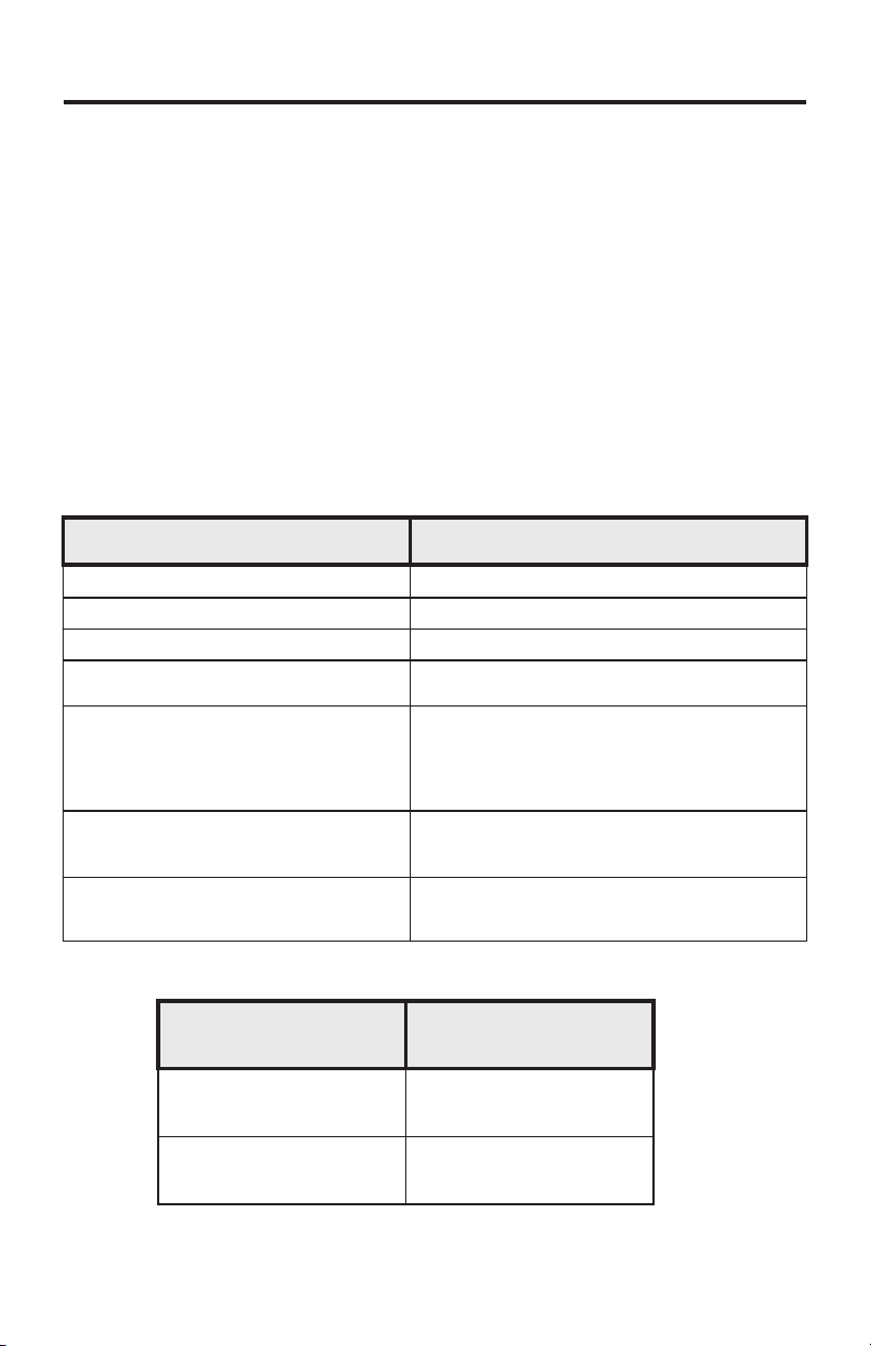
Series Comparison:
PHP-800
PHP-800ESC
Junction
Box
Optional
P
DFD
(Leak Detection)
P
P
External Communications (input)
FVS**
(Flow Verification)
4-20 mA
P
P
0-10 VDC
P
Pulsed*
P
Output
Alarm Relay
Batch
3 Amp
P
P
P
* Also known as Frequency Mode
** Requires Sensor sold separately
P
Page 4
1.0 Introduction
Congratulations on purchasing thePHP-800 Series Diaphragm Metering
Pump. The pump is designed to inject chemicals into piping systems
and is capable of injecting against a high system pressure up to 175 PSI
/ 12.1 bar*.
2.0 Specifications
Maximum Working Pressure* ..............175 psig / 12.1 bar
Maximum Fluid Temperature ...............130 F / 54 C
Ambient Temperature Range . ..............14 to 115 F / -10 to 46.1 C
Output adjustment Range....................1-100% in 0.1% increments
Turn Down Ratio.................................... 100:1
Duty Cycle ............................................Continuous
Maximum Viscosity .. .............. ..............1,000 Centipoise
Maximum Suction Lift ..........................15 ft. water / 4.5 m water
Enclosure Rating.................... ..............NEMA 4X / IP66
Power Requirements .............. ..............115v, 50/60Hz 1.5 Amp
Shipping Weight ....... .............. ..............29 lb. (approx.)
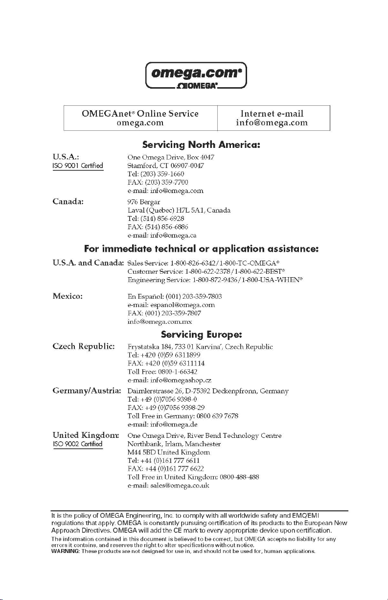
Dimensions:
Diaphragm Metering Pump
Program
MODE
Minimum
Maximum
A
PRIME
IP66
NEMA 4X
Made in the USA
B
C
o o
o o
230v, 50/60Hz 0.7Amp(optional)
E
Junction
Box
Inches
Dim
A
D
5-3/4”
13-1/8”
B
C
9”
8”
D
10-3/4”
E
Page 3
mm
144.8
332.7
228
203.2
274.3
3.0 Features
Oversized PVDF double ball valves.
Operator friendly digital touch pad.
– Easy to read Back Lit LCD display
– Display percentage of motor speed
DFD, Built-in Diaphragm Failure Detection system.
Priming / degassing valve built into the pumphead
NEMA 4X and IP66 rated enclosure
* Depending on model selection.
Page 5
Page 4
4.0 Unpacking
Your pump package should contain the following:
1 - Metering Pump
1 - 8 foot / 2.4 meter suction tube, clear PVC
1 - foot valve & strainer assembly
1 - Injection fitting with internal back -f low check val ve
1 - Mount in g hardware ki t (two mounting b rackets, 4 sc re ws)
1 - 5 Foot / 1.5 meter Priming Tubing
1 - Extra Brush Kit (located inside motor housing)
5.0 Installation
CAUTION: Always wear protective clothing, face shield, safety
glasses and gloves when working on or near your metering pump.
Additional precautions should be taken depending on the solution
being pumped. Refer to MSDS precautions from your solution
supplier.
5.1 Mounting Location
Choose an area located near the chemical supply tank, chemical injection point,
and electrical supply. Install the pump where it can be easily serviced.
!
Mount the pump to a secure surface using the enclosed hardware.
!
Mount the pump close to the injection point. Keep the inlet (suction) and outlet
(discharge) tubing as short as possible. Longer discharge tubing increases the
back pressure at the pump head.
!
Your solution tank should be sturdy. Keep the tank covered to reduce fumes. Do
not mount the pump directly over your tank. Chemical fumes may damage the
unit. Mount the pump off to the side or at a lower level than the chemical
container.
!
Be sure your installation does not constitute a cross connection with the drinking
water supply. Check your local plumbing codes.
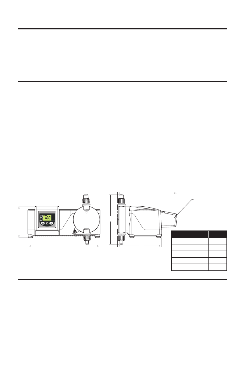
Parts Locator
Control Panel
Priming and
Degassing Valve
Junction Box
Outlet (discharge)
D
i
a
p
h
t
r
m
a
g
m
M
e
t
er
i
n
g
P
u
M
m
OD
p
E
P
r
o
g
r
P
a
m
R
I
ME
M
i
n
i
m
u
m
M
ax
i
m
u
m
M
a
d
e
i
n
t
h
e
U
S
A
I
P
6
6
N
E
M
A
4
X
Pumphead
Mounting Bracket
Inlet (suction)
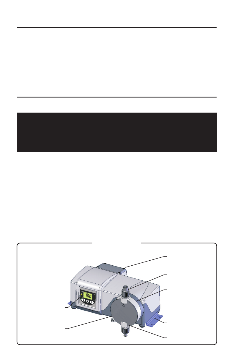
Page 6
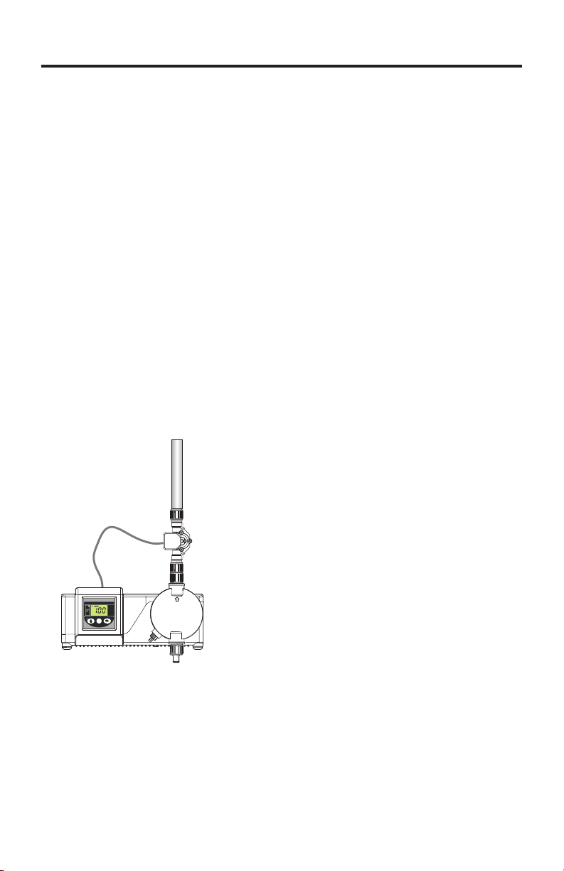
Suction Tubing
Typical Installation
Discharge Tubing
Diaphragm Metering Pump
Program
MODE
Minimum
Maximum
PRIME
IP66
NEMA 4X
Page 5
Injection /
Check Valve
Chemical Tank
Priming /
Degassing Tubing
Foot Valve
Note: All diagrams are strictly for guideline purposes only. Always
consult an expert before installing the pump into specialized systems.
The pump should be serviced by qualified persons only.
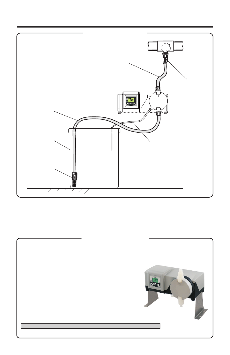
Extended Brackets
Model Number PHP-800-MB
Stainless Steel extended brackets allow the pump to be securely mounted to most any surface;
floor, shelf, or skid. The brackets lift the pump up 4-1/2 inches (11.43 cm), allowing you to easily
connect the suction side of the pump to your solution.
nRaise metering pump 4-1/2 inches (11.43 cm)
off the ground or a surface.
nMade out of tough Stainless Steel.
nProvides a stable mounting surface.
Model #
PHP-800-MB
Extended Mounting Bracket, 1 Pair, SS, 4 SS Screws
Description
Page 7
Page 6
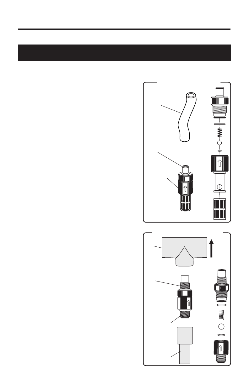
5.2 How To Install the Tubing and Fittings
CAUTION: Proper eye and skin protection must be worn when
installing and servicing the pump and fittings.
! Suction (Inlet) Tubing
Locate the inlet fitting of the pump head. Push the clear suction tubing onto the
fitting barb.
! Footvalve / Strainer
Trim the inlet end of the suction tubing so
that the strainer will rest approximately two
inches from the bottom of the solution tank.
This will prevent sediment from clogging the
strainer. Press the strainer’s barbed fitting
into the end of the tube. Drop the footvalve /
strainer into the solution tank.
Footvalve / Strainer
Suction
(inlet)
Tubing
Hose
Barb
FootValve
Strainer
Assembly
! Injection / Check Valve Fitting Installation
The Injection / Check valve fitting is designed
to install directly into 1/2” female pipe
threads. This fitting will require periodic
cleaning, especially when injecting fluids that
calcify such as sodium hypochlorite.
Install the Injection / Check valve directly into
the piping system. To prevent trapped
gasses, install the fitting in an upward
direction. Use Teflon thread sealing tape on
the pipe threads.
At high pressures, Omega recommends
using a threaded connection.
Injection / Check Valve is available with 1/2”
Male NPT or 1/2” Hose Barb. This is based
on the outlet connection selected for the
pump.
Keep discharge (outlet) tube as short as
possible.
Injection / Check Valve
Pipe
Tee
1/2” Male
NPT
1/2” Male NPT
(optional 1/2”
Hose Barb)
Discharge
Pipe or
1/2” Tubing
(not included)
Install
upward
for best
results
Page 8
Page 7
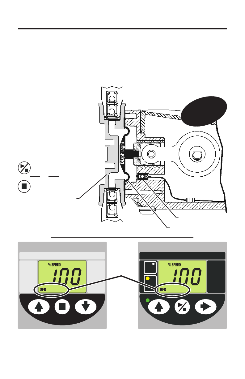
5.3 DFD (Diaphragm Failure Detection)
The Pump includes DFD sensors built directly into the pump. Although it doesn’t
happen often, diaphragm failure can occur. The DFD sensors will detect the
chemical behind the diaphragm caused by diaphragm failure. The pump will then
shut down and energize an internal 3 amp relay. You can wire the 3 amp relay to an
alarm, SCADA system, backup pump, or nothing at all.
Outlet
(discharge)
If the DFD Alarm has been
triggered, the diaphragm
must be replaced and the
pumphead must be
thoroughly cleaned.
You can reset the DFD
alarm by pressing the
Start/Stop button.
PHP-800-ESC
or
PHP-800
Pumphead
(suction)
PHP-800 Display
Diaphragm Metering Pump
Diaphragm
Failure
Detection
ALARM ALARM
Inlet
NEMA 4X
IP66
DFD ALARM
icons
lt
ui
B
h
p
ia
D
DFD Sensors
Diaphragm
PHP-800-ESC Display
Diaphragm Metering Pump
MODE
PRIME
-I
r
D
a
ete
gm F
DFD
n
on
ti
c
Program
Minimum
Maximum
ure
l
ai
Made in the USA
Made in the USA
NEMA 4X
If the DFD Alarm is triggered, the DFD and ALARM icons will begin
flashing.
Note: The DFD system will not reset until you have removed all traces of chemical
from behind the diaphragm.
IP66
Page 9
Page 8
- (sensor and adaptor Fittings
5.4 Flow Verification System
sold separately)
The Pump is equipped with a Flow Verification System which is designed to stop
the pump and provide a contact closure output in the event the sensor does not
detect flow during pump operation. This could indicate a clogged injection fitting,
empty chemical solution tank, loose tubing connection, etc.
To allow the pump to clear any gasses that may have accumulated during
stopper operation (such as with chlorine), an alarm delay time value from 1-255
seconds must be programmed (An alarm delay value of 000 seconds disables
the system).
Install the FTB 300 Series Flow Sensor (sold separately) - The Flow
Verification Sensor should be installed on the outlet (discharge) side of the
pump head valve.
Connect the red/white, black, and white wires from the sensor to the red, black,
Contact Closure Alarm Output - A contact closure output (relay) is provided
with the system. The relay can be configured for normally open (factory default)
or normally closed operation by properly positioning the connector plug on the
circuit board .
FTB300
Series
Diaphragm Metering Pump
Program
MODE
Minimum
Maximum
PRIME
IP66
NEMA 4X
Made in the USA
Page 10

6.0 External Input / Output Signal Connection
SIGNAL INPUT/OUTPUT WIRE COLOR CODES
Page 9
INPUT TYPE
ALARM RELAY
connect 2-conductor plug to either
normally open (NO) (factory default)
or normally closed (NC) side of receptacle.
3 AMP MAX @ 125VAC (24VDC)
FLOW VERIFICATION SENSOR (FVS)
WIRE COLOR CODE
PURPLE & PURPLE
RED/WHITE (+ 20VDC)
BLACK (-)
YELLOW (signal)
Page 11
Page 10
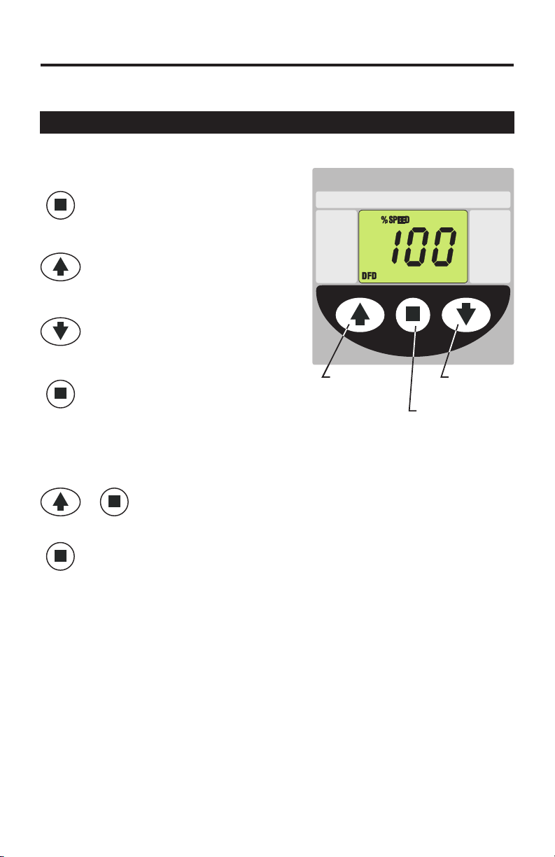
6.1 How To Operate The Pump
Operation
The Pump is a powerful yet simple to
operate metering pump.
To start the pump, press the
Start / Stop button
To increase the output, press
the Up button
To decrease the output, press
the Down button
To stop the pump, press the
Start / Stop button
Priming the Pump
To prime the pump, press the Up button and the Start / Stop
+
To stop priming before the 60 seconds, press the Start / Stop
button.
button at the same time. The pump will run in prime mode for
60 seconds at 100% output.
| Diaphragm Metering Pump
Diaphragm
Failure
Detection
Increase
output speed
NEMA 4X
Made in the USA
Decrease
output speed
Stop and
Start the pump
IP66
Page 12
7.0 External Input/Output Signal Connection
The pump will accept a variety of external control input signals: 4-20mA, 010VDC, TTL, CMOS, AC Sine waves, contact closures, Hall Effect, NPN. The 420mA and 0-10 VDC loops must be powered. Two types of frequency inputs, AC
sine waves (magnetic coils type outputs) and Digital Square waves (Hall Effect
signals, contact closures), are acceptable.
All wiring connections are to be made inside of the junction box located on the
side of the Pump. liquid-tite connectors are supplied and should be used for the
external signal cables. The signal input wires are color coded to the type of
signal being used.
SIGNAL INPUT/OUTPUT WIRE COLOR CODES
Page 11
INPUT TYPE
4-20 mA
0-10 VDC
AC sine wave, TTL, CMOS
CONTACT (10v @ 2 mA max)
HALL EFFECT, NPN
connect 2-conductor plug to either
normally open (NO) (factory default)
or normally closed (NC) side of receptacle.
3 AMP MAX @ 125VAC (24VDC)
FLOW VERIFICATION SENSOR (FTB300)
ALARM RELAY
MOTOR ON SIGNAL
5-20V DC open collector output
closed while motor is energized
PADDLEWHEEL SENSOR SIGNAL INPUT WIRING
PADDLEWHEEL
SENSOR TYPE
HALL EFFECT SENSOR
AC SINE WAVE SENSOR
WIRE COLOR CODE
BLUE (+) (non-powered) & BLACK (-)
ORANGE (+) & BLACK (-)(non-powered)
WHITE (+) & BLACK (-)
RED (+) & WHITE (-)
PURPLE & PURPLE
RED/WHITE (+ 20VDC)
BLACK (-)
YELLOW (signal)
BROWN (+) & BLACK (-)
PUMP INPUT
WIRE COLOR CODE
RED (+ 20VDC)
BLACK (-)
WHITE (signal)
WHITE (+)
BLACK (-)
Page 13

Page 12
7.1 How To Operate The Pump
Operation
MODE button is used to
MODE
select the mode you would
like to run the pump in. See
below for more MODE
information.
PRIME button is used to
prime the pump. The pump
PRIME
will run at full speed for 60
seconds.
To stop the priming
function before the 60
seconds, press the
Start/Stop button.
UP button is used to
change the selected digit.
Start/Stop button is used to
Start and Stop the pump.
RIGHT button is used to
select the digit to program.
PRIME
Button
Green LED
Indicates
pump is
pumping
MODE Selection Button
Diaphragm Metering Pump
MODE
PRIME
Made in the USA
UP button,
To Change
Selected Digit
Start/Stop,
To start and stop
the pump
Program
Minimum
Maximum
IP66
NEMA 4X
Right button,
To Select Digit
To Program
Page 14

Modes
MODE 0 = DFD (Diaphragm Failure Detection) On/Off
FTB300 flow verification system 0 = OFF, 1-255 Seconds = ON
Please Note: You will not see the FVS icon or be able to configure
the FVS unless an FVS sensor is wired to the PHP-800
MODE 1 = Manual Adjustment, 1 - 100% (external input disabled)
MODE 2 = 4-20 mA input
MODE 3 = 0-10 VDC input
MODE 4 = Frequency input (Hz), also known as pulse input
Frequency (Hz) mode is commonly used in proportional feed
systems. Pump can be wired to a paddlewheel flowmeter,
ultrasonic flowmeter, or any type of high frequency flowmeter.
Pump will smoothly speed up and slow down based on frequency
signals. Range = 1 - 1000 Hz
MODE 5 = Batch
Batch mode can be used with water meters, contact closure switch,
and other single pulse or low pulse equipment.
In Batch mode, the pumps’ ‘motor speed’ and ‘on time’ is
configured to be initiated by a single pulse or multiple pulses (up to
1,000 pulses). In MODE 5 the pump ‘motor speed’ is fixed
(1 - 100%) for a specified amount of ‘on time’ (0.1 - 199.9 seconds
or 0.1 - 199.9 minutes).
Page 13
Tip! To View current Input value
From an external source
Press and hold the UP button to toggle from current pump speed
output to current Input value.
Page 15

Page 14
7.2 OPERATING MODE 1 - Output adjusted manually
In this mode, the pump’s motor speed is adjusted manually using the
front panel touch pad. The motor speed can be adjusted from 0-100%.
4
Set the pump for mode 1.
Press the MODE button until MODE 1
is shown on the LCD display.
MODE
The %SPEED icon will light.
The large LCD will indicate the
currently programmed percentage of
speed.
4
Enter the programming mode.
Press and MODE button for more than
MODE
two seconds.
Mode 1
Diaphragm Metering Pump
MODE
PRIME
Program
Minimum
Maximum
A blinking ARROW will point to the
word PROGRAM indicating the
Made in the USA
program mode has been activated.
Press the Right button to select the digit to program. The digit will blink
when selected.
Press the UP button to change the selected digit.
Repeat until all digits are programmed.
To exit the programming mode, press the MODE button for more than two
MODE
seconds.
The arrow next to the word PROGRAM will disappear.
[
NOTE: If while in the program mode no buttons are pressed within 20
seconds, the circuitry will automatically return to the run mode, without
saving changes.
IP66
NEMA 4X
Page 16

7.3 OPERATING MODE 2 - 4-20 mA input Mode
In this mode, the pump’s motor speed is adjusted automatically based on the
value of the 4-20 mA input signal. Any motor speed can be assigned to either
the minimum or maximum milliamp input values.
4
Set the pump for mode 2.
Press the MODE button until MODE 2
MODE
is shown on the LCD display.
The %SPEED or mA icon will light
depending on the current display
setting.
Press and hold the UP button to toggle
from current pump speed output to
current Input mA signal.
The large LCD will indicate the current
motor speed or the current mA input
value.
4
Enter the programming mode.
While MODE 2 is displayed, press the MODE button
for more than two seconds.
MODE
Blinking ARROW’s will point to the words PROGRAM
and MINIMUM indicating the program mode is
activated and the minimum value is ready to be
programmed. The % SPEED icon will blink indicating
the percentage of speed is ready to be programmed.
Mode 2
Diaphragm Metering Pump
MODE
PRIME
Made in the USA
C3V | Diaphragm Metering Pump
MODE
PRIME
Page 15
Program
Minimum
Maximum
IP66
NEMA 4X
Program
Minimum
Maximum
4
Enter the motor speed at the minimum mA input
signal value.
Blue-White Ind.
Press the RIGHT button to select the digit to program.
Made in the USA
The digit will blink when selected.
Press the UP button to change the selected digit.
Repeat until all digits are programmed.
Press the MODE button. The % SPEED icon will stop blinking and the mA
icon will blink indicating the minimum mA value is ready to be programmed.
MODE
The currently programmed minimum value is shown on the LCD.
4
Enter the minimum mA input signal value.
Note: this value must be less than the maximum mA input signal value.
Press the RIGHT button to select the digit to program. The digit will blink
when selected.
Press the UP button to change the selected digit.
IP66
NEMA 4X
Page 17

Page 16
MODE
4
Repeat until all digits are programmed.
Press the MODE button. The mA icon will stop blinking
and the % SPEED icon will blink. The ARROW next to
C3V | Diaphragm Metering Pump
the word MAXIMUM will blink indicating the maximum
value is ready to be programmed. The currently pro-
MODE
grammed maximum motor speed value is shown on the
LCD.
PRIME
Enter the motor speed at the maximum mA input
signal value.
Program
Minimum
Maximum
Press the RIGHT button to select the digit to program.
The digit will blink when selected.
Blue-White Ind.
Made in the USA
Press the UP button to change the selected digit.
Repeat until all digits are programmed.
Press the MODE button. The % SPEED icon will stop
blinking and the mA icon will blink indicating the
MODE
maximum mA value is ready to be programmed. The
currently programmed maximum value is shown on the
LCD.
4
Enter the maximum mA input signal value.
Note: this value must be greater than the minimum mA input signal value.
Press the RIGHT button to select the digit to program. The digit will blink
when selected.
Press the UP button to change the selected digit.
Repeat until all digits are programmed.
Press the mode button. Programming is complete.
MODE
To exit the programming mode, press the MODE button for more than two
MODE
seconds. The PROGRAM arrow will disappear.
IP66
NEMA 4X
Page 18

Mode 2 Programming Examples
Page 17
Pump Output
20%
Output
Pump Output
0%
Output
Motor Speed
100%
75%
50%
25%
0%
100%
75%
6
8
4
from external source
12
10
Milliamp input (mA)
16
20
18
14
Example 1
4 mA will result in a pump output of
70%
20.0%
Output
16 mA will result in a pump output of
70.0%
Example 2
100%
Output
4 mA will result in a pump output of 0.0%
50%
Motor Speed
25%
0%
6
8
4
Milliamp input (mA)
from external source
10
16
20
18
14
12
20 mA will result in a pump output of
100.0%
Tip! To View current Input value
Press and hold the UP button to toggle from current pump speed
output to current Input value.
Page 19

Page 18
7.4 OPERATING MODE 3 - 0-10 VDC Mode
In this mode, the pump’s motor speed is adjusted automatically based on the
value of the 0-10VDC input signal. Any motor speed can be assigned to either
the minimum or maximum DC input signal values.
4
Set the pump for mode 3.
Mode 3
Press the MODE button until MODE 3
MODE
is shown on the LCD display.
Diaphragm Metering Pump
The % SPEED or VDC icon will light
depending on the current display
setting.
Press and hold the UP button to toggle
MODE
PRIME
from current pump speed output to
current VDC Input value.
The large LCD will indicate the current
motor speed or the VDC input value.
4
Enter the programming mode.
Made in the USA
While MODE 3 is displayed, Press and hold the MODE button for more than
two seconds.
MODE
Blinking ARROW’s will point to the words PROGRAM and MINIMUM
indicating the program mode is activated and the minimum value is ready to
be programmed. The % SPEED icon will blink indicating the percentage of
speed is ready to be programmed.
4
Enter the motor speed at the minimum VDC input signal value.
Press the RIGHT button to select the digit to program. The digit will blink
when selected.
Program
Minimum
Maximum
IP66
NEMA 4X
MODE
Press the UP button to change the selected digit.
Repeat until all digits are programmed.
Repeat until all digits are programmed.
4
Press the MODE button. The % SPEED icon will
stop blinking and the VDC icon will blink indicating
the minimum VDC value is ready to be programmed.
The currently programmed minimum value is shown
on the LCD.
Enter the minimum VDC input signal value.
Note: this value must be less than the maximum VDC input signal value.
Program
Minimum
Maximum
Page 20

Press the RIGHT button to select the digit to program. The digit will blink
when selected.
Press the UP button to change the selected digit.
Repeat until all digits are programmed.
4
Press the MODE button. The VDC icon will stop
blinking and the % SPEED icon will blink. The
ARROW next to the word MAXIMUM will blink
MODE
indicating the maximum value is ready to be
programmed. The currently programmed maximum
motor speed value is shown on the LCD.
4
Enter the motor speed at the maximum VDC igit.
4
input signal value.
Press the RIGHT button to select the digit to program. The digit will blink
when selected.
Press the UP button to change the selected digit.
Repeat until all digits are programmed.
Press the MODE button. The % SPEED icon will stop blinking and the VDC
icon will blink indicating the maximum VDC value is ready to be pro-
MODE
grammed. The currently programmed maximum value is shown on the LCD.
4
Enter the maximum VDC input signal value.
Note: this value must be greater than the minimum VDC input signal value.
Page 19
Program
Minimum
Maximum
MODE
MODE
Pump Output
0%
Output
Press the RIGHT button to select the digit to program. The digit will blink
when selected.
Press the UP button to change the selected digit.
Repeat until all digits are programmed.
Press the MODE button. Programming is complete.
To exit the programming mode, press and hold the MODE button for more
than two seconds. The PROGRAM arrow will disappear..
Mode 3 Programming Examples
Motor Speed
100%
75%
50%
25%
0%
2
0
4
VDC input
from external source
8
6
10
Example 1
0 VDC will result in a pump output of
70%
0.0%
Output
8 VDC will result in a pump output of
70.0%
Page 21

Page 20
100%
90%
Output
75%
50%
25%
0%
Pump Output
Motor Speed
Continued - Mode 3 Programming Examples
Example 2
0 VDC will result in a pump output of
90%
0%
10 VDC will result in a pump output of
Output
0.0%
8
2
0
4
VDC input
from external source
6
10
100%
75%
100%
Output
Example 3
0 VDC will result in a pump output of
Pump Output
0%
Output
50%
Motor Speed
25%
0%
2
0
from external source
4
VDC input
8
6
10
0.0%
10 VDC will result in a pump output of
100.0%
Tip! To View current Input value
Press and hold the UP button to toggle from current pump speed
output to current Input value.
7.5 OPERATING MODE 4 - Frequency (Hz) Mode
Also known as Pulse Input. In this mode, the pump’s motor speed is adjusted
automatically based on the frequency (Hz) of the input signal. Any motor speed
can be assigned to either the minimum or maximum Hz input signals.
4
Set the pump for mode 4.
Press the MODE button until MODE 4
MODE
is shown on the LCD display.
The % SPEED or Hz icon will light
depending on the current display
setting.
Press and hold the UP button to toggle
from current pump speed output to
current Hz Input value.
Mode 4
Diaphragm Metering Pump
MODE
PRIME
Program
Minimum
Maximum
The large LCD will indicate the current
motor speed or the Hz input value.
4
Enter the programming mode.
Made in the USA
IP66
NEMA 4X
Page 22

While MODE 4 is displayed, press and hold the MODE button for more than
MODE
two seconds.
Blinking ARROW’s will point to the word PROGRAM and MINIMUM
indicating the program mode is activated and the minimum value is ready to
be programmed. The % SPEED icon will blink indicating the percentage of
speed is ready to be programmed.
4
Enter the motor speed at the minimum Hz input signal value.
Press the RIGHT button to select the digit to program. The digit will blink
when selected.
Press the UP button to change the selected digit.
Repeat until all digits are programmed.
Press the MODE button. The % SPEED icon will stop
MODE
blinking and the Hz icon will blink indicating the
minimum Hz value is ready to be programmed. The
currently programmed minimum value is shown on
the LCD.
4
Enter the minimum Hz input signal value (to the nearest 10 Hz).
Note: this value must be less than the maximum Hz input signal value.
Press the RIGHT button to select the digit to program. The digit will blink
when selected.
Page 21
Program
Minimum
Maximum
Press the UP button to change the selected digit.
Repeat until all digits are programmed.
Press the MODE button. The Hz icon will stop
blinking and the % SPEED icon will blink. The
MODE
ARROW next to the word MAXIMUM will blink
indicating the maximum value is ready to be programmed. The Currently programmed maximum
motor speed value is shown on the LCD.
4
Enter the motor speed at the maximum VDC input signal value.
Press the RIGHT button to select the digit to program. The digit will blink
when selected.
Press the UP button to change the selected digit.
Repeat until all digits are programmed.
Press the MODE button. The % SPEED icon will stop blinking and the Hz
icon will blink indicating the maximum Hz value is ready to be programmed.
MODE
The currently programmed maximum value is shown on the LCD.
Program
Minimum
Maximum
Page 23

MODE
MODE
Pump Output
0%
Output
90%
Output
Pump Output
Pump Output
0.0%
Output
Enter the maximum Hz input signal value (to the nearest 10 Hz).
Note: this value must be greater than the minimum Hz input signal value.
Press the RIGHT button to select the digit to program. The digit will blink
when selected.
Press the UP button to change the selected digit.
Repeat until all digits are programmed..
Press the MODE button. Programming is complete.
To exit the programming mode, press and hold the MODE button for more
than two seconds. The PROGRAM arrow will disappear.
Mode 4 Programming Examples
Motor Speed
Motor Speed
Motor Speed
100%
75%
50%
25%
0%
100%
75%
50%
25%
0%
100%
75%
50%
25%
0%
200
0
0
0
400
Hz input
from external source
200
400
Hz input
from external source
200
400
Hz input
from external source
600
600
600
800
800
800
1000
1000
1000
Example 1
100%
Output
0 Hz will result in a pump output of 0.0%
1000 Hz will result in a pump output of
0.0%
Example 3
0 Hz will result in a pump output of
90.0%
0%
1000 Hz will result in a pump output of
Output
0.0%
Example 3
0 VDC will result in a pump output of
0.0%
50.0%
Output
800 Hz will result in a pump output of
50.0%
Tip! To View current Input value
Page 22
Press and hold the UP button to toggle from current pump speed
output to current Input value.
Page 24

Page 23
7.6 - OPERATING MODE 5 - Batch Mode
In this mode, the pump’s ‘motor speed’ and ‘on time’ is configured to be initiated
by a single pulse or up to 1,999 pulses.
You will configure the pump in the following order:
a. Select the % SPEED.
(1% to 100%)
b. Select the pump ON time.
(0.1 to 199.9 and select units: seconds (SEC) or minutes (MIN)
c. Select the amount of pulses to receive to trigger the pump.
(1 pulse up to 1999 pulses)
4
Set the pump for mode 5.
Press the MODE button until MODE 5
MODE
is shown on the LCD display.
The % SPEED and Hz icon will light.
The large LCD will indicate the current
motor speed or the Hz input value.
4
Enter the programming mode.
While MODE 5 is displayed, press and
hold the MODE button for more than
MODE
two seconds.
Blinking ARROW’s will point to the
word PROGRAM and MINIMUM
A blinking ARROW will point to the word PROGRAM and the % SPEED icon
will blink indicating the program mode is activated and the % SPEED value
is ready to be programed.
4
Enter the motor speed. (1% to 100%)
Mode 5
Diaphragm Metering Pump
MODE
PRIME
Made in the USA
Program
Minimum
Maximum
IP66
NEMA 4X
Press the RIGHT button to select the digit to program. The digit will blink
when selected. (Moves to the next digit to the right.)
Press the UP button to change the selected digit.
Repeat until all digits are programmed.
Press the MODE button. The % SPEED icon will stop blinking and the SEC
or MIN icon will blink indicating the pump ON-time value is ready to be
MODE
programmed.
4
Enter the pump ON-time. (0.1 to 199.9 seconds or minutes)
Press the RIGHT button to select the digit to program. The digit will blink
when selected. (Moves to the next digit to the right.)
Press the UP button to change the selected digit.
Repeat until all digits are programmed.
Page 25

Once all the digits are programmed, press the RIGHT arrow to then select
between SEC (seconds) and MIN (minutes).
Use the UP arrow to scroll through SEC and MIN.
Press the MODE button. The SEC or MIN icon will stop blinking and the Hz
MODE
icon will blink indicating the number of pulses is ready to be programmed.
4
Enter the number of pulses to trigger the batch. (1 to 1999 pulses)
Press the RIGHT button to select the digit to program. The digit will blink
when selected. (Moves to the next digit to the right.)
Press the UP button to change the selected digit.
Repeat until all digits are programmed.
Press the MODE button. Programming is complete.
MODE
To exit the programming mode, press and hold the MODE button for more
MODE
than two seconds. The PROGRAM arrow will disappear.
Tip! To View current Input value
Press and hold the UP button to toggle from current pump speed
output to current Input value.
Page 24
CAUTION: Always wear protective clothing, face shield, safety glasses and gloves
when working on or near your metering pump. Additional precautions should be
taken depending on the solution being pumped. Refer to MSDS precautions from
your solution supplier.
Page 26

Page 25
8.0 Measuring the Pump’s Output - Volumetric Test.
This volumetric test will take into account individual installation factors such as
line pressure, fluid viscosity, suction lift, etc. This test is the most accurate for
measuring the injector’s output in an individual installation.
1. Be sure the Injection Fitting and Footvalve /
Strainer are clean and working properly.
2. Fill a large graduated cylinder with the
solution to be injected.
3. With the pump installed under normal
operating conditions, place the suction
tubing with the Footvalve / Strainer installed
in the graduated cylinder.
4. Push 3/8” tubing onto the priming valve.
Place the other side of the 3/8” tubing in the
solution tank. Make sure the priming valve
is closed by turning the valve to the right.
5. Run the pump until all air is removed from
the suction line and the solution enters the
discharge tubing.
If the pump does not easily prime, loosen
the priming valve 1 - 2 turns counter clock
wise. Once the air is removed close the
priming valve.
6. Remove the suction tubing from the
graduated cylinder and refill the graduated
cylinder if necessary. Note the amount of
solution in the graduated cylinder.
lace suction tubing with the Footvalve / Strainer installed back into the
7. P
graduated cylinder.
8. Run the injector for a measured amount of time. A longer testing time will
produce more accurate results.
9. Remove the suction tubing from the graduated cylinder. Measure the amount
of chemical injected.
Example:
During your 1 minute calibration period, say the Chem-Pro pumped 1000
Milliliters in 1 minute.
Injection Fitting /
Check Valve
Discharge / Outlet
(not provided)
Diaphragm Metering Pump
Program
MODE
Minimum
Maximum
PRIME
IP66
NEMA 4X
Made in the USA
3/8” Priming
Tubing
(not provided)
Graduated
Container
(not provided)
Footvalve /
Strainer
Suction
Tubing
1 US Gallon = 3.785 Liters = 3785 Milliliters
1000 ML/Min
3785
Note: All diagrams are strictly for guideline purposes only. Always consult an expert
before installing the pump into specialized systems. The pump should be serviced
by qualified persons only.
60 = 15.85 GPH (US gallons per hour)
Minutes per hour
Milliliters in a US gallon
Page 27

9.0How to Maintain the Pump
CAUTION: Proper eye and skin protection must be worn when
installing and servicing the pump.
9.1Routine Inspection and Maintenance
The pump requires very little maintenance. However, the pump and all accessories should be checked regularly. This is especially important when pumping
chemicals. Inspect all components for signs of leaking, swelling, cracking,
discoloration or corrosion. Replace worn or damaged components immediately.
Cracking, crazing, discoloration and the like during the first week of operation
are signs of severe chemical attack. If this occurs, immediately remove the
chemical from the pump. Determine which parts are being attacked and replace
them with parts that have been manufactured using more suitable materials.
The manufacturer does not assume responsibility for damage to the pump that
has been caused by chemical attack.
Brush Kit Life Cycle over 3,000 hours of continuous use.(Part number
72000-378)
9.2How to Clean the Pump
The pump will require occasional cleaning, especially the Injection fitting, the
Footvalve / Strainer, and the pump head valves. The frequency will depend on
the type and severity of service.
]
Inspect and replace the pumphead valves as required.
]
When changing the diaphragm, the pump head chamber and pump head
cover should be wiped free of any dirt and debris.
]
Periodically clean the injection / check valve assembly, especially when
injecting fluids that calcify such as sodium hypochlorite. These lime deposits and
other build ups can clog the fitting, increase the back pressure and interfere with
the check valve operation.
]
Periodically clean the suction strainer.
]
Periodically inspect the air vents located under the motor housing and in the
back on the rear housing cover. Clean if necessary.
Page 26
Page 28

Page 27
PUMP HEAD AND VALVE EXPLODED VIEW
Page 29

Page 28
Replacement Parts Drawing
22
30
16
13
17
29
18
19
20
15
12
28
6
14
3
1
5
8
21
25
7
23
11
27
26
0
1
24
21
9
2
4
Page 30

PARTS LIST
Item Part No. Description Qty.
1. 71000-583 J-Box w/ Cover 1
2. 90001-158 P-Head Cover 1
3. 90008-035 Liquid Tight Connector (large) 1
90008-199 Liquid Tight Connector (small) 1
4. 90011-081 Screw P-Head Cover SS 2
5. 71000-584 Cover housing model (std.) 1
71000-585 Cover housing model (ESC) 1
6. 71000-175 Power Cord,115v 1
71000-176 Power Cord,220v 1
71000-177 Power Cord,230v 1
7 72000-382 Controller Kit model (Std.) 115V 1
72000-383 Controller Kit model (Std.) 230V 1
72000-384 Controller Kit model (esc) 115V 1
72000-385 Controller Kit model (esc) 230V 1
8. 90012-287 Label Overlay model (std) 1
90012-289 Label Overlay model (deluxe) 1
9. 90011-181 Screw P-Head SS # 10-32 x 1.25L 8
10. 90011-094 Washer SS #10 screw 4
11. 90011-180 Screw Nylon #8-32 4
12. 90003-560 Diaphragm TFE/Hypalon 1
13. 90003-561 Bumper Feet 4
14. 71000-588 Frame Housing Assy. 1
- Includes TFD Sensor
15. 76001-347 Backup Washer Diaphragm 1
16. 90011-115 Screw for housing 10-32x.50L SS 10
17. 76000-361 Tubing Suction .75” OD x .50” ID x 8ft 1
18. 70002-276 Motor 130RPM 1
70002-277 Motor 62RPM 1
19. 90008-367 Clamp Heat Sink 1
20. 90011-182 Screw #10-32 x .31 SS 2
21. 20000-194 Kit 4 cartridge insert Viton 4
20000-195 Kit 4 cartridge insert EP 4
22. 71000-573 Cam .06’ S/A complete 1
71000-574 Cam .10’ S/A complete 1
23. 90002-258 Pump Head molded PVDF 1
24. 70001-347 Cart. Valve Assy. .50T Viton 1
70001-348 Cart. Valve Assy. .50T EP 1
25. 70001-349 Cart. Valve Assy. .50 Male NPT/Viton 1
70001-350 Cart. Valve Assy. .50 Male NPT/EP 1
70001-351 Cart. Valve Assy. .50 Female NPT Viton 1
70001-352 Cart. Valve Assy. .50 Female NPT EP 1
26. 70001-353 Primer Valve Assy. Viton 1
70001-354 Primer Valve Assy. EP 1
27. 70001-356 Kit Head Complete .50T & .50M/NPT Viton 1
70001-357 Kit Head Complete .50T & .50M/NPT EP 1
70001-358 Kit Head Complete .50T & .50F/NPT Viton 1
70001-359 Kit Head Complete .50T & .50F/NPT EP 1
28. 71000-575 Foot Valve Assy. Viton 1
71000-576 Foot Valve Assy. EP 1
29. 90008-043 Clamp #5 SS 1
30. 71000-579 Injection Valve Assy. Viton 1
71000-580 Injection Valve Assy. EP 1
Bearings
Bumper Feet
Page 31

NOTES
Page 30Page 29
Page 32

Page 33

Page 34

Where Do I Find Everything I Need For
Process Measurement and Control?
OMEGA... Of Course!
Shop on line at www.Omega.com
TEMPERATURE
Thermocouple, RTD & Thermistor Probes, Connectors, Panels & Assemblies
Wire: Thermocouple, RTD & Thermistor
Calibrations & Ice Point References
Recorders, Controllers & Process Monitors
Infrared Pyrometers
PRESSURE / STRAIN FORCE
Transducers & Strain Gauges
Load Cells & Pressure Gauge
Displacement Transducers
Instrumentation & Accessories
FLOW / LEVEL
Rotameters, Gas Mass Flowmeters & Flow Computers
Air Velocity Indicators
Turbine / Paddlewheel Systems
Totalizers & Batch Controllers
pH / CONDUCTIVITY
pH Electrodes, Testers & Accessories
Benchtop / Laboratory Meters
Controllers, Calibrators, Simulators & Pumps
Industrial pH & Conductivity Equipment
DATA ACQUISITION
Thermocouple, RTD & Thermistor Probes, Connectors, Panels & Assemblies
Wire: Thermocouple, RTD & Thermistor
Calibrations & Ice Point References
Recorders, Controllers & Process Monitors
Infrared Pyrometers
HEATERS
Heating Cable
Cartridge & Strip Heaters
Immersion & Band Heaters
Flexible Heaters
Laboratory Heaters
ENVIRONMENTAL MONITORING AND CONTROL
Metering & Control Instrumentation
Refractometers
Pumps & Tubing
Air, Soil & Water Monitors
Industrial Water & Wastewater Treatment
pH, Conductivity & Dissolved Oxygen Instruments
M-4630/0408
 Loading...