

Page 1
PHP-400 SERIES
Chemical Metering Pumps
;fE
OMEGA
READ ALL CAUTIONS CAREFULLY
BEFORE INSTALLING PUMP
Operator’s Manual
OMEGA”)
Technologies
An L
Company
d
Ml
757/I
093
Page 2

Servicing USA and Canada: Call OMEGA Toll Free
OMEGA Engineering, Inc.
One Omega Drive, Box 4047
Stamford, CT 06907-0047 U.S.A.
Headquarters: (203) 359-1660
Sales: I-800-826-6342
Customer Service: I-800-622-2378
Engineering: I-800-872-9436
FAX: (203) 359-7700 TELEX: 996404 EASYLINK: 62968934 CABLE OMEGA
/
I-800-TC-OMEGA
/
I-800-622-BEST
/
I-800-USA-WHEN
Servicing Europe: United Kingdom Sales and Distribution Center
OMEGA Technologies Ltd.
25 Swannington Road, Broughton Astley, Leicestershire
6TU,
England
FAX: 44 (0455) 283912
EncyclopediasTM
&
pH
and Conductivity
v
I/
Data Acquisition Systems
v
Electric Heaters
LE9
Telephone: 44 (0455) 285520
The OMEGA Complete Measurement and
Control Handbooks
v
Temperature
v
Pressure, Strain
r/
Flow and Level
& Force
Call for Your FREE Handbook Request Form Today: (203)
359-RUSH
Page 3
TABLE OF CONTENTS
SAFETY INSTRUCTIONS .............................................................................................................................
INTRODUCTION
............................................................................................................................................
UNPACKING THE PUMP ..............................................................................................................................
PRECAUTIONS FOR OPERATION
INSTALLATION, PIPING AND WIRING
START-UP AND OPERATION
MAINTENANCE
TROUBLESHOOTING
SPECIFICATIONS
...........................................................................................................................................
.................................................................................................................................
.......................................................................................................................................
EXPLODED VIEW DRAWING
SAFETY INSTRUCTIONS
...............................................................................................................
.........................................................................................................
.....................................................................................................................
.....................................................................................................................
-1
When using chemical feed pumps, basic safety precau-
tions should always be followed to reduce risk of fire,
electric shock, and personal injury. Failure to follow
these instructions could result in death or serious injury.
READ ALL INSTRUCTIONS
3
4
5
5
7
11
13
15
16
17
GENERAL SAFETY CONSIDERATIONS
??
Always wear protective clothing including gloves and safety glasses when working on or near chemical
metering pumps.
??
Inspect tubing regularly when replenishing chemical solution for cracking or deterioration and replace as
necessary. Always wear protective clothing and safety glasses when inspecting tubing.
??
When pump is exposed to direct sunlight use U.V. resistant tubing.
??
Follow directions and warnings provided with the chemicals from the chemical manufacturer. Customer is
responsible for determining chemical compatibility with chemical feed pump.
??
Secure chemicals and metering pumps making them inaccessible to children and pets.
??
Make sure voltage on chemical metering pump matches the voltage at the installation.
-
??
Do not cut plug off electrical cord or the ground lug
??
Pump is NOT to be used to handle flammable liauids.
consult a licensed electrician for proper installation.
SAFETY OPERATING PROCEDURES
??
All pumps are tested with water before shipment. Remove head and dry thoroughly if you are pumping chemical
that will react with water (i.e. sulfuric acid). Valve seats, ball checks, gaskets and diaphragm should also be dried.
??
Finger tighten connections on pump head. DO NOT USE WRENCH. Teflon tape is only necessary when pump
is equipped with NPT connections.
??
Before repair or moving pump, disconnect power cord or turn off power to pump. De-pressurize system and
drain chemical. (Always wear protective clothing and safety glasses when working on metering pump.)
??
Always consult licensed plumber and electrician before installation and make sure to conform to local codes.
??
Consult with local health officials and qualified water conditioning specialist when treating potable water.
??
Be sure to de-pressurize system prior to hook-up or disconnection of metering pump.
??
If point of injection is lower than chemical tank and pump, install an anti-siphon valve.
??
DO NOT MODIFY pump, poses potentially dangerous situation and voids
war=y.
??
For accurate volume output, pump must be calibrated under all operating
3
conditons.
Page 4
INTRODUCTION
These installation, operation and maintenance instructions cover your electronic metering pump. Refer to the
pump nameplate to determine the actual model.
w
PRINCIPLE OF OPERATION
Diaphragm metering pumps are used to dispense chemicals or fluids. This is achieved by an electromag-
netic drive mechanism (solenoid) which is connected to a diaphragm. When the solenoid is pulsed by the
control circuit, it displaces the diaphragm which, through the use of check valves, moves the fluid out the
discharge under pressure. When the solenoid is deenergized it returns the diaphragm and pulls more fluid
into the pump head and the cycle repeats.
The pump stroke rate is controlled by the internal circuit and is changed by turning the rate knob. The
mechanical stroke length of the pump is controlled by the stroke length knob.
W
MATERIALS OF CONSTRUCTION
The wetted materials (those parts that contact the solution being pumped) available for construction are
polypropylene, 316 Stainless Steel, and PVDF. These materials are very resistant to most chemicals.
However, there are some chemicals, such as strong acids or organic solvents, which cause deterioration
of some elastomer and plastic parts, such as diaphragm, valve seat, or head. Consult Chemical Resistance
Guide or OMEGA for information on chemical compatibility.
Various manufacturers of plastics, elastomers and pumping equipment publish guidelines that aid in the
selection of wetted materials for pumping commercially available chemicals. Two factors must always be
considered when using an elastomer or plastic part to pump chemicals. They are:
1.
The temperature of service: Higher temperatures increase the effect of chemicals on wetted materials.
The increase varies with the material and the chemical being used. A material quite stable at room
temperature might be affected at higher temperatures.
2.
Material choice: Materials with similar properties may differ greatly from one another in performance
when exposed to certain chemicals.
4
Page 5
UNPACKING THE PUMP
Remove the Packing List and verify that you have received all equipment. If you have any
about the shipment, please call the OMEGA Customer Service Department at l-800-622-2378 or (203)
359-1660. Inspect the container and equipment for any signs of damage. Note any evidence of rough
handling in transit. Immediately report any damage to the shipping agent.
questions
NOTE:
unless all shipping material is saved for their
examination. After examining and removing
contents, save packing material and carton
in the event reshipment is necessary.
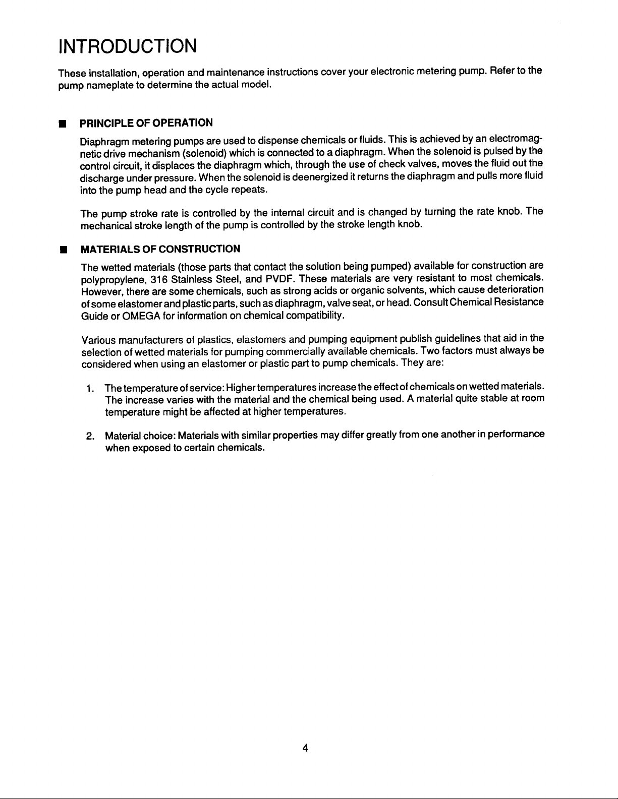
The carton should contain: (See Figure A)
-
Metering Pump
I-
Clear Flexible Suction Tubing
-
Stiff White Discharge Tubing
-
Foot Valve/Strainer Assy.
-
Back Pressure Injection Valve Assy.
-
One Instruction Book that you are
-
Bleed Valve Assembly (most models)
*
??
The carrier will not honor any claims
now reading
NOT SUPPLIED WITH
AISI-316SS PUMPS.
Make sure that all items have been
removed from the shipping carton
before it is discarded.
Figure A
PRECAUTIONS FOR OPERATION
.
Each Electronic Metering Pump has been tested to meet prescribed specifications and safety standards. Proper
care in handling, installation and operation will help in ensuring a trouble free installation
Please read all these cautionary notes prior to installation and start-up of your metering pump.
Important: Pump must be installed and used with supplied back pressure/injection valve.
1.
Failure to do so could result in excessive pump output
Handle the pump with care. Dropping or heavy impact may cause not only external damage to the
2.
pump, but also to electrical parts inside.
Install the pump in a place where the ambient temperature does not exceed 40°C (104°F) and relative
3.
humidity below 90%. The pump is water resistant and dust proof by construction and can be
do
outdoors,
do not operate in direct sunlight.
Install the pump in a place convenient for its future maintenance and inspection, then fix it to prevent
4.
vibration. Rubber pads are provided for table top operation,
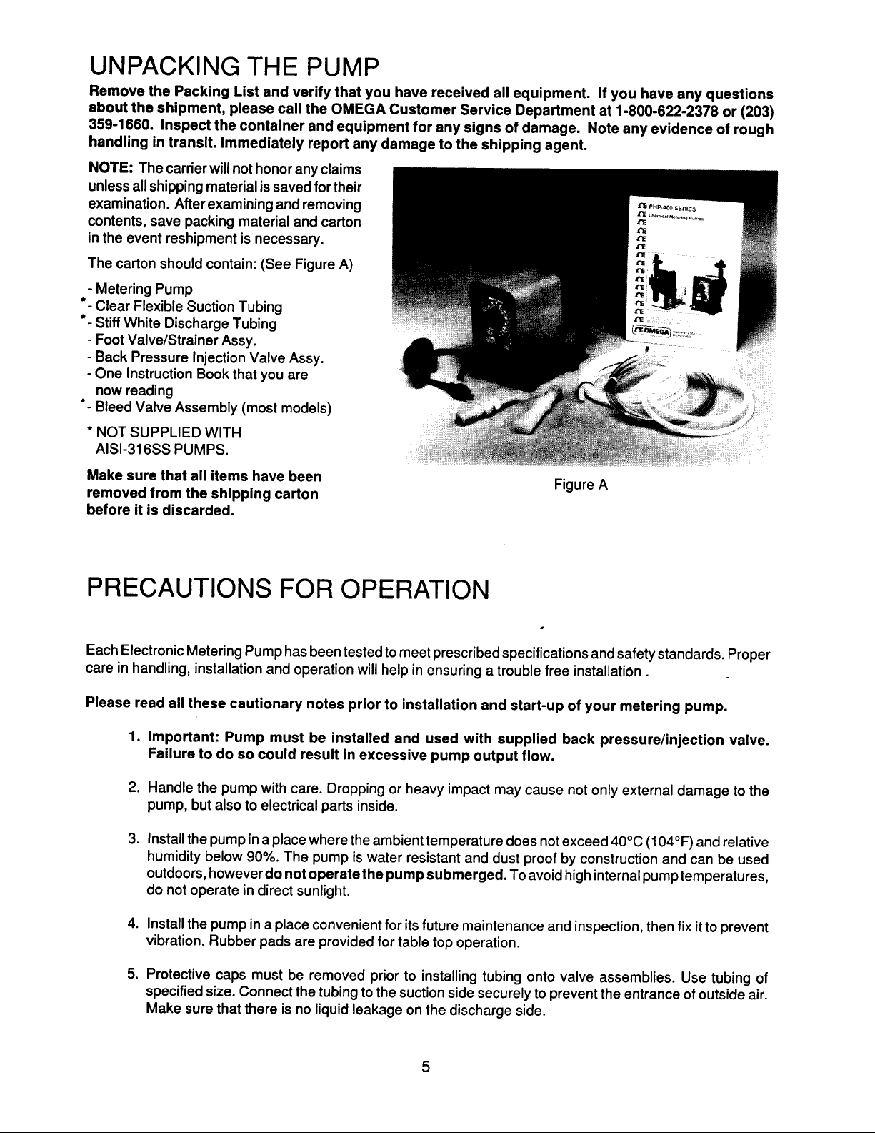
Protective caps must be removed prior to installing tubing onto valve assemblies. Use tubing of
5.
specified size. Connect the tubing to the suction side securely to prevent the entrance of outside air.
Make sure that there is no liquid leakage on the discharge side.
however
not operate the pump submerged.
flow.
To avoid high internal pump temperatures,
.
used
5
Page 6
6. Be careful to check that the voltage of the installation matches the voltage indicated on the pump
nameplate. Each pump is equipped with a three-prong plug. Always be sure the pump is grounded.
To disconnect, do not pull wire but grip the plug with fingers and pull out. Do not use the receptacle in
common with heavy electrical equipment which generates surge voltage. It can cause the failure of the
electronic circuit inside the pump.
7. Tampering with electrical devices can be potentially hazardous. Always place chemicals and pump
installation well out of the reach of children.
8. Never repair or move the metering pump while operating. Always disconnect electrical power.
For
safety, always wear protective clothing (protective gloves and safety glasses) when working
on or near chemical metering pumps.
9.
An air bleed valve is available for all models with tubing connection. Air purges should be performed
when the pump chamber contains no fluid at the time of start-up. As a safety measure, connect the
return tubing to the air bleed valve and bypass fluid back to storage tank or a suitable drain.
10. Chemicals used may be dangerous and should be used carefully and according to warnings on the
label. Follow the directions given with each type of chemical. Do not assume chemicals are the same
because they look alike. Always store chemicals in a safe location away from children. OMEGA cannot
be responsible for the misuse of chemicals being fed by the pump. Always have the material safety data
sheet (MSDS) available for any fluid being pumped.
11. All pumps are pretested with water before shipment. Remove head and dry thoroughly if you are
pumping a material that will react with water, (i.e. sulfuric acid). Valve seats, ball checks, gaskets, and
diaphragm should also be dried. Before placing pump into service, extreme care should be taken to
follow this procedure.
12.
Valve cartridges are stamped to indicate fluid flow direction. Always install so that markings read from
top to bottom.
13. When metering hazardous material DO NOT use plastic tubing. Strictly use proper rigid pipe. Consult
OMEGA for special adaptors or valve assemblies.
14. Pump is NOT to be used to handle or meter flammable liquids or materials.
15. Standard white discharge tubing is not recommended for installations exposed to direct sunlight.
Consult OMEGA for special black tubing.
16.
Factory will not be held responsible for improper installation of pump, or plumbing. All cautions are to
be read thoroughly prior to hook-up and plumbing. For all installations a professional plumber should
be consulted. Always adhere to local plumbing codes and requirements.
17. When using pump with pressurized systems, make sure the pressure of the system does not exceed
the maximum pressure rating on the pump nameplate. Be sure to de-pressurize system prior to hook-
up or disconnecting the metering pump.
18.
Electronic power modules are equipped with automatic reset thermal overload devices and may reset
unexpectedly.
6
Page 7

INSTALLATION, PIPING AND WIRING
The metering pump should be located in an area that allows convenient connections to both the chemical storage
tank and the point of injection. The pump is water resistant and dust proof by construction and can be used
outdoors, however
do otherwise will result in damage to the pump.
MOUNTING
Typical mounting arrangements are shown in Figures B to E.
do not operate submerged. Avoid continuous temperatures in excess of 40°C
(104°F).
To
Important:
VALL
IOUNT
Injection point must be higher than the top of the solution supply tank to prohibit
gravity feeding, unless suitable backpressure is always present at the injection point.
INJECTIO N
INJECTIO N
POINT
P
D
FIG
For
1.
2.
3.
wall or shelf mounting, refer to Figure B. Connect suction tubing to suction valve of chemical pump.
Suction valve is the lower valve. Tubing should be long enough so that the
about 2-3 inches above the bottom of chemical tank. To keep chemical from being contaminated, the tank
should have a cover.
Flooded suction mounting (installing the
trouble free type of installation and is recommended for very low output requirements. Since the suction
tubing is filled with chemical, priming is accomplished quickly and the chance of losing prime is reduced.
To mount pump, drill
4 holes of
pump securely using four
The pump can be mounted to a wall as shown in Figure
D. A wall mount bracket kit is available which includes
all necessary hardware to mount the pump to the
bracket and the bracket to the wall. Mounting the pump
other than as shown in Figure D defeats the purpose of
the housing drain. Mounting dimensions for the pump
are provided in Figure F for reference.
1/4”diameterin
#lO bolts and nuts.
pump at
the base of the chemical storage tank, Figure
the shelf as shown in
7
FIG
E
footvalve/strainer assembly hangs
the dimension
drawing (Figure F). Attach
Figure F
C) is the most
Page 8

The pump can be mounted on top of a solution tank as shown in Figure E. Install chemical pump on the
4.
cover. Insert suction tubing through the center hole and cut tubing so
inches above the bottom of the tank. Mount the chemical pump rigidly by drilling four
#lO screws and nuts.
four
USE AN ANTI-SIPHON VALVE IN THE DISCHARGE LINE whenever the fluid pressure in the discharge
5.
line is below atmospheric pressure. This can occur if the injection point is on the suction side of a water
pump or against a “negative ” head such as when feeding down into a well, SEE FIGURE
TYPICAL DOMESTIC WATER TREATMENT INSTALLATION
footvalve/strainer hangs about 2-3
l/4”
holes and using
Gl
.
Gl
FIG
TYPICAL COOLING TOWER INSTALLATION
FIG
G2
FIG
G3
PIPING
1.
Use provided tubing of specified size for connection. Connect tubing securely to prevent leakage of
chemical and the entrance of air. Since plastic nuts are used for fittings, they should not be tightened
excessively i.e. hand tighten only.
2.
If the air bleed valve assembly is being used, a return line (tubing) should be securely connected and routed
back to the storage tank.
To avoid possible injury from chemicals do not attempt to prime using a
bleed valve without installing a return line.
When pump is shelf mounted or top mounted on tank, suction tubing should be kept as short as possible.
3.
4.
To maintain metering performance, a back pressure/injection valve is provided. The injection
be installed in the discharge line. Best practice is to install the injection valve at the point of chemical
injection.
8
valve must
Page 9

If the discharge tubing
5.
standard white translucent tubing supplied with each pump. To obtain, contact OMEGA.
6.
To prevent clogging or check valve malfunction always install a strainer assembly to the end of the suction
tubing (Figure E). This
bottom of the chemical tank. This will help prevent clogging the strainer with any solids that may settle on
the tank bottom. The chemical tank and
continuous trouble free operation. If the chemical being pumped regularly precipitates out of solution or
does not dissolve easily or completely (e.g. calcium hydroxide), a
mixer should be used in the chemical tank. These are readily
available in many motor configurations and mountings. To obtain,
contact OMEGA.
A flooded suction (tank liquid level always at a higher elevation than
7.
the pump) is recommended when pumping sodium hypochlorite
(NaOCI)
produce air bubbles. Maintaining a low liquid temperature will also
help eliminate this problem
Pipe corrosion can result if dilution at the injection point does not
8.
occur rapidly. This problem is easily prevented by observing this
simple rule: install injection fitting so that the end is in the center of
the flow stream of the line being treated. Trim injectortipas required.
See Figure H. Note: Extended injection assemblies are available for
large water lines. Consult OMEGA for more information.
and hydrazine solution
is going to be exposed to direct sunlight, black tubing should be used instead of the
footvalve/strainer assembly should always be installed 2 to 3 inches above the
footvalve/strainer should be cleaned regularly, to ensure
(N2H2)
etc. which are liable to
.
WIRING
The metering pump should be wired to an electrical source which conforms to those on the pump
1.
nameplate. (Applying higher voltage than the pump is rated for will damage the internal circuit.)
W I-
2.
Risk of electrical shock. This pump is supplied with a three prong grounding
type power plug. To reduce risk of electric shock, connect only to a properly grounded, grounding
type receptacle.
In the electronic circuit of the control unit, measures for surge voltage are made by means of surge
3.
absorbing elements and high voltage semiconductors. Nevertheless, excessive surge voltage may cause
failure in some areas. Therefore, the receptacle should not be used in common with heavy electrical
equipment which generates high voltage. If this is unavoidable, however, measures should be taken by (a)
the installation of a surge absorbing element (varisterof min. surge resistance 2000A) to the power supply
connection of the pump, or (b) the installation of a noise suppression transformer.
NOISE SUPPRESSIO N
Page 10

WELL PUMP SYSTEM INSTALLATION
1.
Ensure that
well pump. Typical
the metering
pump voltage matches the
well pump electrical circuits are shown
voltage of the
in
Figure I. All electric wiring should be installed in accordance to
local electrical codes by a licensed electrician.
2.
Install the back pressure/injection valve on the discharge side
of the metering pump into a tee which is installed into the water
line going to the pressure tank. A typical installation is shown in
VALVE ASS ’
Figure G.
FIG J
Pumps carrying the NSF seal are listed for swimming pools, spas, and hot tubs, and when proper materials
are selected, are capable of handling but not limited to the following chemical solutions:
12%%
sodium hypochlorite
2% calcium hypochlorite
20% dichloro-s-triazinone
5% trichloro-s-triazinone
12% aluminum sulphate
10% hydrochloric acid
10% sodium hydroxide
5% sodium carbonate
115 VOLT SYSTEM WIRING DIAGRA M
FIG
10
230 VOLT SYSTEM WIRING DIAGRA M
I
Page 11

START UP
AND OPERATION
POWER
50/60
50/60
All metering pumps are available in 115 volts at
Hertz, single phase. Optionally 230 volts at
Hertz,
single phase can be provided. Prior to start-up always check to insure that the pump voltage/frequency/
phase matches that of the power supply.
PRIMING
-1:
When working on or around a chemical metering pump installation, protective clothing
and gloves and safety glasses should be worn at all times.
All pumps are tested with water. If the chemical to be pumped reacts when mixed with
water (e.g. sulfuric acid) the
pumphead
should be removed and dried thoroughly along
with the diaphragm and valve seats.
Plug the pump into an appropriate outlet.
1.
Adjust the stroke rate knob to the 100% setting mark (for more information see “Capacity Control ”)
2.
Adjust the stroke length knob to the 100% setting mark (for more information see “Capacity Control ”).
3.
If the discharge line is connected directly to a pressurized
4.
system it should be temporarily bypassed during priming of
the pump. A bleed valve will simplify this operation by allowing
easy bypass of the discharge fluid. All air must be purged from
the
pumphead
Bleed Operation:
Air
Whilepumpisrunning,turnadjustmentscrewcoun-
A)
terclockwise.
Run with valve open until a solid stream of fluid
B)
comes out of the bypass tubing
with valve), no air bubbles.
Close air bleed valve by turning adjustment screw
C)
clockwise.
Chemical should reach the
5.
and moisten the discharge valve area (ball check and valve seats) with a few drops of chemical being fed
to the metering pump.
before the pump will pump against pressure.
3/8
x
supplied
(l/4
pumphead after a few minutes of operation. If not, remove the discharge fitting
For safety, always use protective clothing and gloves, wear safety glasses and
use a proper container to hold the chemical.
.
6.7.If the pump continues to refuse to prime, refer to Troubleshooting Section of these instructions.
Once the pump has been primed and is pumping the chemical through the head, turn off the power,
reconnect the discharge tubing (if it had been removed) and immediately clean any spilled chemical that
is on the pump housing or head.
Turn the power on once more and adjust the pump flow to the desired rate (see “Capacity Control ”).
8.
Always check the calibration of the pump after start-up. It ’s best to calibrate the pump under your typical
9.
use conditions.
11
Page 12

CAPACITY CONTROL
Capacity can be controlled by means of the stroke length adjusting knob or stroke frequency adjusting knob.
Graphs are for illustration purposes only. Use a calibration column for accurate calibration. Contact
OMEGA
for
proper calibration equipment.
(1) Stroke Frequency Adjustment:
?
Stroke frequency can be controlled from 10
to 100% (12 to 125 sp m ) by m eans of the
electronic circuit.
?
frequency can be set by means of the
Stroke
stroke frequency adjusting knob even while
the pu mp is in operation.
60
STROKE
RATE%
(2) Stroke Length Adjust m ent:
?
Stroke length can be controlled within 0 to
100% of the diaphrag m displace ment. (It
should be controlled within 10 to 100% for
practical use.)
I
Stroke length can be set by means of the
stroke length adjusting knobwhile the pump
is in operation. Do
not turn the knob while
the pump is stopped.
Controlling Procedure:
(3)
Proper set points for stroke length and stroke frequency should be determined after consideration of the pump
and characteristics of the fluid. The following procedure is reco mm ended fro m the viewpoint of pu mp
perfor m ance. Note: The closer the stroke length is to 100% the better the pu mp perfor mance w ill
PERCENT STROKE
3
20
be.
Set the stroke length to 100% then adjust the stroke frequency for coarse capacity control.
A)
Measure the capacity.
B)
When the m easured capacity is less than the required value, increase the stroke frequency and
Cl
measure the capacity again.
Then, adjust the stroke length for fine capacity control.
D)
Finally, m easure the capacity and make sure that the required value is obtained.
El
=
PHP-404ExamDIe Selected Model
=
=
=
=
=
=
100%
100%
GPD*
30
12 GPD
0.50 x 30
12 x 100
15
GPD ’
=
15
=
80% approx.
50%,
i.e. output capacity
=
Set Stroke Length
Set Stroke Rate
Output Capacity
(Rated Pressure)
Des ired Flow
Adjust Stroke Rate to 80%
Output Capacity
Stroke Length Setting
Thus to obtain the desired flow, stroke length is set at 80% and stroke rate is set at
=
0.80 x 0.50 x 30
??
Check these values by measurement. Output capacity is higher when feeding against less than rated
12 GPD*
pressure.
12
Page 13

MAINTENANCE
m
: Before performing any maintenance or repairs on chemical metering pumps, be sure to
disconnect all electrical connections and insure that all pressure valves are shut off and
pressure In the pump and lines has been bled off.
Always wear protective clothing, gloves and safety glasses when performing any mainte-
nance or repairs on chemical metering pumps.
ROUTfNE
1,
2.
3.
4.
MAINTENANCE
Routinely check
excessive vibration, low flow and pressure output or high temperatures
maximum stroke rate, the pump housing temperature can be up to 160°F
For optimum performance, cartridge valve assemblies should be changed every 4-6 months. Depending on
the application, more frequent changes may be required. Actual operating experience is the best guide in
this situation. Repeated short-term deterioration of valve seats and balls usually indicates a need to review
the suitability of wetted materials selected for the application. Contact OMEGA for guidance.
Check for leaks around fittings or as a result of deteriorating tubing, e.g. when standard white translucent
discharge tubing is exposed to direct sunlight. Take appropriate action to correct leak by tightening fittings
or replacing components.
Keep the pump free of dirt/debris as this provides insulation and can lead to excessive pump temperatures.
the physical operating condition of the pump.
Look for
the presence of any abnormal noise,
[when running constantly at
(7O”C)].
5.
If the pump has been out of service for a month or longer, clean the
puma
fresh water for approximately 30 minutes. If the
replace cartridge valve assemblies.
does not operate normally after this “purging run”,
pumphead/valve assemblies by pumping
DISASSEMBLY AND ASSEMBLY
DIAPHRAGM REMOVAL
1.
2.
3.
4.
5.
pumphead and valve assemblies out by running pump on water or other suitable neutralizing solution.
Flush
Wash outside of pump down if chemical has dripped on pump.
Set stroke length of pump to 0% and unplug pump.
Disconnect tubing or piping from the pump. Remove the four
pumphead
Remove the diaphragm by grasping it at the outer edges and turning it counterclockwise until it unscrews
from the electronic power module (EPM). Don ’t lose the deflection plate or diaphragm shims which are
behind the diaphragm. Note shim quantity can be from 0 to 2.
Inspect diaphragm if it is intended to be used again. Look for indications of the Teflon face being
overstretched, (localized white areas) or the elastomer on the back of the diaphragm being worn. Excessive
amounts of either condition require diaphragm replacement.
assembly.
pumphead
screws and then remove the
13
Page 14

DIAPHRAGM REPLACEMENT
Refer to drawings in the back of the manual.
1.
When replacing the diaphragm, it ’s always
Set pu m p stroke length to 0% and unplug the pu mp.
2.
If you kept the shi m s fro m the original diaphrag m or
3.
know the original quantity you can avoid Step
shimm ing the diaphrag m and go to Step
4.
Slide the diaphragm deflection plate onto the back of the
diaphrag m stud, radius side towards the diaphrag m.
Next slide two shims onto the diaphragm threaded stud
and screw the diaphrag m into the EPM unit. Refer to
sketch. Turn diaphrag m clockwise until it stops turning.
If there is a gap between the adaptor and diaphrag m,
repeat the procedure removing one shim each time until
the diaphrag m just touches the adaptor or is slightly
recessed.
Apply grease to areas of the diaphragm that contact the
5.
deflection plate or radius on the adaptor.
#5.
a good
#4
for
idea
to replace the valve cartridges and other worn parts.
Screw the diaphrag m into the EPM unit ’s shaft with the deflection plate and appropriate nu mber of shi m s
6.
in between.
7.
Adjust stroke length to 50%. It is easier to do this if you temporarily turn the pump on. Place the
onto the adaptor with flow arrows pointing up and install and tighten
pumphead
Adjust stroke length back to 100% for easier pri ming and place pu mp back into service.
8.
pulls up against adaptor.
pumphead screws. Tighten screws until
pumphead
VALVE REPLACEMENT
1.
Flush pump to clean any chemical from pumphead.
2.
Unplug pu m p and d isconnect any tubing or piping.
3.
Unscrew valve cartridges and discard. Also re move O-R ings down inside pu mphead.
4.
Using new O-R ings, install new valve cartridges with sta mped letters reading fro m top to botto m . Hand
tighten only, do not use wrenches or pliers.
5.
Reconnect tubing or piping and reinstall the pu mp.
14
Page 15

TROUBLESHOOTING
‘ROBLEM PROBABLE
1.
Pump setting too low
LOSS OF
2.3.Scale at injection point
CHEMICAL
RESIDUAL
Solution container allowed
to run dry
1.
Pump setting too high
Chemical in solution tank
TOO
MUCH
CHEMICAL
2.
too rich
Siphoning of chemical into
3.
well or main line
Worn tube ends
1.
’
Chemical attack
2.
CAUSE
REMEDY
1.
Adjust to higher setting (pump must be operating during
the stroke length adjustment).
2.
Clean injection parts with 8% muriatic acid or undiluted
vinegar. (Also, see Maintenance Section).
3.
Refill the tank with solution and prime. (See Start-Up
and Operation Section).
1.
Lower pump setting (pump must be operating to adjust
stroke length knob).
2.
Dilute chemical solution. NOTE: For chemical that
reacts with water, it may be necessary to purchase a
more dilute grade of chemical from chemical
supplier.
3.
Test for suction or vacuum at the injection point. If
suction exists, install an anti-siphon valve.
1.
Cut off end of tubing (about 1”) and then replace as
before.
2.
Consult OMEGA for alternate material.
FAILURE
TO PUMP
Leak in suction side of pump
1.
2.
Valve seats not sealing
Low setting on pump
3.
4.
Low solution level
5.
Diaphragm ruptured
Pump head cracked or broken
6.
7.8.Pump head contains air or
chlorine gas
Breakdown or disconnection
of wiring
9.
Voltage drop
10.
Malfunction of electronic
control board
1.
Examine suction tubing. If worn at the end, cut
approximately an inch off and replace.
2.
Clean valve seats if dirty or replace with alternate
material if deterioration is noted.
3.
When pumping against pressure, the dials should be set
above 20% capacity for a reliable feed rate.
4.
Solution must be above foot valve.
5.
Replace diaphragm as shown in the “Maintenance Section.”
Check for pressure above rated maximum at the injection
point. NOTE: Chemical incompatibility with diaphragm
material can cause diaphragm rupture and leakage around
the pump head.
6.
Replace pump head as shown in “Maintenance Section.”
Make sure fittings are hand tight only. Using pliers
and wrench can crack pump head. Also, chemical
incompatibility can cause cracking and subsequent
leakage.
7.
After turning off all pressure lines, disconnect
discharge tubing and install bleed valve assembly.
8.
Connect wiring properly. Check fuse or circuit breaker.
9.
Take corrective measures after investigation of cause.
10. Contact OMEGA.
15
Page 16

‘ROBLEM
FITTING
LEAKAGE
PUMP
WILL NOT
PRIME
PROBABLE CAUSE
1.2.Dirty check valve
Ball checks not seating or
not sealing properly
Solution container allowed
3.
to run dry
1.
Loose fittings
Broken or twisted gasket
Chemical attack
Too much pressure at
discharge
2 . Check valves not sealing
REMEDY
Remove and replace or clean off any scale or sediment.
1.
2.
Check seat and ball checks for chips, clean gently. If
deformity or deterioration is noted, replace part with
proper material. Resulting crystals can hold check
valves open, therefore the valves must be disassembled
and cleaned. Be sure to replace all parts as shown in
the Parts Diagram (at the end of the manual).
3.
Refill container with proper chemical.
1.
All fittings can be hand tightened to prevent leakage.
Clean off chemicals which have spilled on pump.
2.
Check gaskets and replace if broken or damaged.
3.
Consult OMEGA for alternate material.
1.
Turn off all pressure valves, loosen outlet tubing
connection at discharge
cartridge. Dampen ball check and valve seats with a few
drops of solution. Set pump dials to maximum rate.
W hen pump is primed, reconnect all tubing connections.
Disassemble, loosen, clean and check for deterioration
2.
or swelling. Reassemble and wet the valve assembly,
then prime. See Start-Up and Operating Section.
pcint. Remove discharge valve
3.
Output dials not set at
maximum
4.
Suction lift height too much
5.
Pump equipped with spring
loaded high viscosity valves
PHP-400
SERIES SPECIFICATIONS
POWER:
LIQUID END:
VALVE BALLS:
SEALS:
DIAPHRAGM:
METERING RANGE:
MAXIMUM FREQUENCY:
NOMINAL POWER:
PEAK POWER
CONSUMPTION:
DIMENSIONS:
WEIGHT:
Always prime pump with output dials set at maximum
3.
rated capacity.
Decrease suction lift or pull vacuum on pump discharge
4.
until pump is primed.
Loosen discharge valve to aid in priming, take necessary
5.
safety precautions, or apply vacuum to pump discharge.
ilSVac,60Hz
“G”
Glass-filled polypropylene on
and 316 SS on
Ceram ic for “G” and
Hypalon for
“G”
“s”
models
and
“K”
models; Teflon for
“K”
models; Teflon for “S” models
models, PVDF on
Teflon-faced Hypalon
10 to 100% of capacity
125 strokes/minute
50 Watts
130 Watts
10 ”Hx5 ”Wx95 ”D(250x127x241
10 Ibs. (4.5 kg)
mm )
“s”
models
“K”
models,
16
Page 17

)
I TEM
1
( EPM )
OTY
1
1
1
1
1
1
1
1
1
1
1
4
1
1
I*
1
I TEM
5 0 ELECTRON ICPO W ERMODUL E
5 1
r;?
;;.
5 5 FEMALE ADJUSTMENT SHAF T
5 6 MALE ADJUSTMENT SHAF T
58
5 9 CONTROL PANEL O - R I NG
CE I-l-l U” t. D”
*l-l
aLC” I. V r.I\I
“1
61 r
62 r
6 3 FUS E
6L
7 1
??
COMPONENTS OF I TEM 9 3
115 VOLT EPM UN I TS HAVE GREY LEADS .
230 VOLT EPM UN I TS HAVE RED LEADS .
PART NAM E
HOUS
I NG
F ,- TF ),-, N I T
F I
___L.l._..._
CONTROL PANE L
EPM l HOUS l NG
STRA I N REL I E F
PO W ER CORD
CONTROL PANEL SCREW
KNOB .STROKE
r” NTQOL
__...I.
O - R I N G
CEd l
dLr . L
LENGT H
BOAR , ,
/
7 2 KNOB MOUNT I NG SCREW
74
76
77 *
7 0 ELECTRON I C
7 9
81
*II
_._.
0 9 GROUND LUG BOL T
9 0 GROUND LUG W ASHER 3
9 3 CONTRO LPANEL SUB - ASSEMBL Y
PART NAM E
EPM MOUNT I NG SCREW
ZTROKE
T;Rn MMFT
_ .
_
PANEL LABE L
EPM MOUNT I NG WASHE R
._
II
CONTRC -
~D” ll h l ”
. _
. __ I
_ ,
LENGT H
_1_ _ .
I NOT
: ONTROL
I
lr; II I
- 1 ..
ASSEM8LY
.rl UT
PANEL
SHO W N )
BOARD SCRE W 2
I
I
4
OTY
I
1
4
1
1
I
J
1
3
1
1
Al
3EF
SECT ION /PAGE
I
REV I S I ON UPOAT E
I
I
DATE
EFFECT IVE
SUPERSEDES NEW
02 / 1 & 192p
DRIVE ASSEMBLY
cn r
By :
DWN
DATE :
O lI OB l 92
AC00140
17
PHPQOO SERIES
Page 18

=*
OUANTITY
VARIES
-
SHIM AS REQUIRED
LJPOATED TO NEW STRAINER .
1
t
REVISIO N
HHK.
1
DAT E
18
PUMP HEAD ASSEMBLY
‘m
‘ATE:
BY:
j-8-92
CMF
0WG.r
CAD
AC00139.00 1
Page 19

M E
A
m
OMEGA warrants this unit to be free of defects
service for a period of 13
month grace period to the normal
time. This ensures that our customers receive maximum coverage on each product. If the unit should
malfunction, it must be returned to the factory for evaluation. Our Customer Service Department will
issue an Authorized Return (AR) number immediately upon phone or written request.
examination by OMEGA, if the unit is found to be defective it will be repaired or replaced at no charge.
However, this WARRANTY is VOID if the unit shows evidence of having been tampered with or shows
evidence of being damaged as a result of excessive corrosion; or current, heat, moisture or vibration;
improper specification; misapplication; misuse or other operating conditions outside of OMEGA ’s
control. Components which wear or which are damaged by misuse are not warranted. These include
contact points, fuses, and
months from date of purchase. OMEGA Warranty adds an additional one
triacs.
WARRANTY
in materials and workmanship and to give satisfactory
1
year product warranty to
(I
one
(I)
cover handling and shipping
Upon
We are glad to offer suggestions on the use of our various products. Nevertheless OMEGA
only warrants that the parts manufactured by it will be as specified and free of defects.
OMEGA MAKES NO OTHER WARRANTIES OR REPRESENTATIONS OF ANY KIND
WHATSOEVER, EXPRESSED OR IMPLIED, EXCEPT THAT OF TITLE AND ALL IMPLIED
WARRANTIES INCLUDING ANY WARRANTY OF MERCHANTABILITY AND FITNESS FOR A
PARTICULAR PURPOSE ARE HEREBY DISCLAIMED.
LIMITATION OF LIABILITY: The remedies of buyer set forth herein are exclusive and the
total liability of OMEGA with respect to this order, whether based on contract, warranty,
negligence, indemnification, strict liability or otherwise, shall not exceed the purchase
price of the component upon which liability is based. In no event shall OMEGA be liable for
consequential, incidental or special damages.
Every precaution for accuracy has been taken in the preparation of this manual; however, OMEGA
ENGINEERING, INC. neither assumes responsibility for any omissions or errors that may appear nor
assumes liability for any damages that result from the use of the products in accordance with the
information contained in the manual.
/
RETURN REQUESTS
INQUIRIES
Direct all warranty and repair requests/inquiries to the OMEGA ENGINEERING Customer Service
Department. Call toll free in the USA and Canada: I-800-622-2378, FAX: 203-359-7811; International:
203-359-I 660,
BEFORE RETURNING ANY PRODUCT(S) TO OMEGA, YOU MUST OBTAIN AN AUTHORIZED RETURN
(AR) NUMBER FROM OUR CUSTOMER SERVICE DEPARTMENT (IN ORDER TO AVOID PROCESSING
DELAYS). The assigned AR number should then be marked on the outside of the return package and
on any correspondence.
FOR
WARRANTY
following information available BEFORE
contacting OMEGA:
1.
P.O. number under which the product was
PURCHASED,
2.
Model and serial number of the product
under warranty, and
3.
Repair instructions and/or specific problems
you are having with the product.
OMEGA’s policy is to make
customers get the latest in technology and engineering.
OMEGA is a registered trademark of OMEGA ENGINEERING, INC.
0
1993 OMEGA ENGINEERING, INC. All rights reserved including illustrations. Nothing in this manual may be reproduced in
any manner, either wholly or in part for any purpose whatsoever without written permission from OMEGA ENGINEERING,
INC.
FAX: 203-359-7807.
RETURNS, please have the
running changes, not model changes, whenever an improvement is possible. That way our
FOR
NON-WARRANTY
consult OMEGA for current repair/calibration
charges. Have the following information available
BEFORE contacting OMEGA:
1.
Your P.O. number to cover the COST of the
repair/calibration,
2.
Model and serial number of product, and
3.
Repair instructions and/or specific problems you
are having with the product.
REPAIRS OR
CALIBRATION,
19
Page 20

OMEGA?..
Your Source
for
Process Measurement and Control
TEMPERATURE
B’
Thermocouple, RTD &Thermistor Probes, Connectors, Panels
m
Wire: Thermocouple, RTD &Thermistor
&
IZi’
Calibrators
III’
Recorders, Controllers
w
Infrared Pyrometers
PRESSURE/STRAIN FORCE
Ice Point References
&
Process Monitors
&
Assemblies
I@
Transducers
m
Load Cells
w
Displacement Transducers
w
Instrumentation
& Strain Gauges
&
Pressure Gauges
& Accessories
FLOW/ LEVEL
iZf’
Rotameters, Gas Mass Flowmeters
m
Air Velocity Indicators
Turbine/Paddlewheel Systems
w
&
B
Totalizers
Batch Controllers
& Flow Computers
pH/CONDUCTIVITY
pH
@’
@’ Benchtop/Laboratory Meters
R’
IZ!’
Electrodes, Testers
Controllers, Calibrators, Simulators
&
Conductivity Equipment
pH
Industrial
& Accessories
&
DATA ACQUISITION
B
Data Acquisition and Engineering Software
w
Communications-Based Acquisition Systems
m
Plug-in Cards for Apple, IBM
I@ Datalogging Systems
&
w
Recorders, Printers
Plotters
& Compatibles
Pumps
HEATERS
B
Heating Cable
IZ?
Cartridge
II@
Immersion
IZI’
Flexible Heaters
w
Laboratory Heaters
L9403100-000
REV. 1093
&
Strip Heaters
&
Band Heaters
PRINTED IN U.S.A.
 Loading...