

Page 1
http://www.omega.com
e-mail: info@omega.com
User ’s Guide
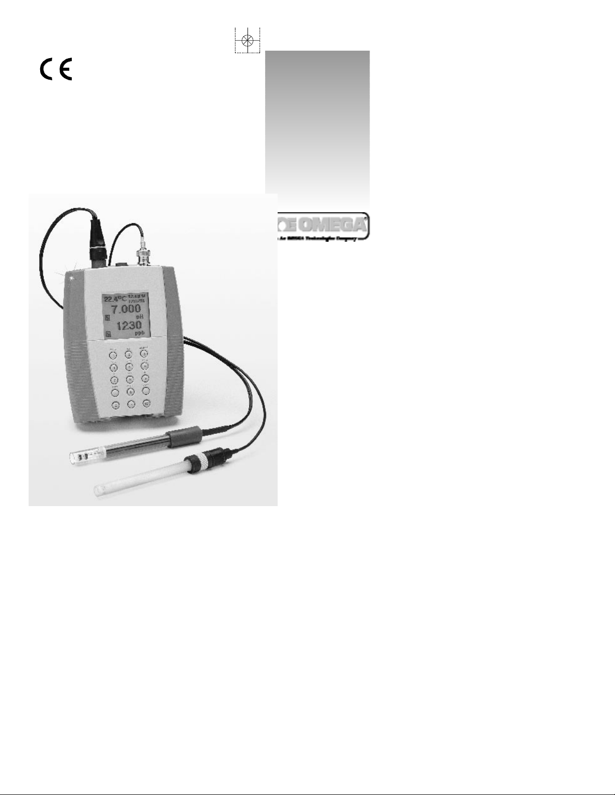
PHH-925 and PHH-950
pH Meters
Page 2

Servicing North America:
USA: One Omega Drive, Box 4047
ISO 9001 Certified Stamford, CT 06907-0047
Tel: (203) 359-1660 FAX: (203) 359-7700
e-mail: info@omega.com
Canada: 976 Bergar
Laval (Quebec) H7L 5A1
Tel: (514) 856-6928 FAX: (514) 856-6886
e-mail: canada@omega.com
For immediate technical or application assistance:
USA and Canada: Sales Service: 1-800-826-6342 / 1-800-TC-OMEGA
SM
Customer Service: 1-800-622-2378 / 1-800-622-BEST
SM
Engineering Service: 1-800-872-9436 / 1-800-USA-WHEN
SM
TELEX: 996404 EASYLINK: 62968934 CABLE: OMEGA
Mexico and
Latin America:
Tel: (95) 800-TC-OMEGA
SM
FAX: (95) 203-359-7807
En Espan÷ol: (203) 359-7803 e-mail: espanol@omega.com
Servicing Europe:
Benelux: Postbus 8034, 1180 LA Amstelveen, The Netherlands
Tel: (31) 20 6418405 FAX: (31) 20 6434643
Toll Free in Benelux: 06 0993344
e-mail: nl@omega.com
Czech Republic: ul. Rude armady 1868, 733 01 Kavrine-Hranice,
Czech Republic
Tel: 420 (69) 6311627 FAX: 420 (69) 6311114
e-mail: czech@omega.com
France: 9, rue Denis Papin, 78190 Trappes
Tel: (33) 130-621-400 FAX: (33) 130-699-120
Toll Free in France: 0800-4-06342
e-mail: france@omega.com
Germany/Austria: Daimlerstrasse 26, D-75392 Deckenpfronn, Germany
Tel: 49 (07056) 3017 FAX: 49 (07056) 8540
Toll Free in Germany: 0130 11 21 66
e-mail: germany@omega.com
United Kingdom: 25 Swannington Road, P.O. Box 7, Omega Drive,
ISO 9002 Certified Broughton Astley, Leicestershire, Irlam, Manchester,
LE9 6TU, England M44 5EX, England
Tel: 44 (1455) 285520 Tel: 44 (161) 777-6611
FAX: 44 (1455) 283912 FAX: 44 (161) 777-6622
Toll Free in England: 0800-488-488
e-mail: uk@omega.com
OMEGAnetSMOn-Line Service Internet e-mail
http://www.omega.com info@omega.com
It is the policy of OMEGA to comply with all worldwide safety and EMC/EMI regulations that
apply. OMEGA is constantly pursuing certification of its products to the European New Approach
Directives. OMEGA will add the CE mark to every appropriate device upon certification.
The information contained in this document is believed to be correct but OMEGA Engineering, Inc. accepts
no liability for any errors it contains, and reserves the right to alter specifications without notice.
WARNING: These products are not designed for use in, and should not be used for, patient connected applications.
Page 3

Quick Start. . . . . . . . . . . . . . . . . . . . . . . . . . . . . . . . . . . . . . . . Page ii
Introduction
Electrode Connector Inputs . . . . . . . . . . . . . . . . . . . . . . . . . . . . 1
Batteries . . . . . . . . . . . . . . . . . . . . . . . . . . . . . . . . . . . . . . . . . . . . 1
LCD Display. . . . . . . . . . . . . . . . . . . . . . . . . . . . . . . . . . . . . . . . . 2
Function Keys. . . . . . . . . . . . . . . . . . . . . . . . . . . . . . . . . . . . . . . . 3
Electrodes
Preparing pH and Ion Selective Electrodes . . . . . . . . . . . . . . . . 4
Preparing Conductivity Cells. . . . . . . . . . . . . . . . . . . . . . . . . . . . 4
Connecting Electrodes . . . . . . . . . . . . . . . . . . . . . . . . . . . . . . . . 5
Using and Storing Electrodes. . . . . . . . . . . . . . . . . . . . . . . . . . . . 6
pH Electrodes. . . . . . . . . . . . . . . . . . . . . . . . . . . . . . . . . . . . . . 6
Solid-State FET Electrodes . . . . . . . . . . . . . . . . . . . . . . . . . . . . 6
Ion Selective Electrodes . . . . . . . . . . . . . . . . . . . . . . . . . . . . . 7
Conductivity Cells . . . . . . . . . . . . . . . . . . . . . . . . . . . . . . . . . . 7
Meter Operation
Setup Menu . . . . . . . . . . . . . . . . . . . . . . . . . . . . . . . . . . . . . . . . . 8
Standardizing and Measuring pH
pH StandardizatIon Menu . . . . . . . . . . . . . . . . . . . . . . . . . . . . . . 9
Standardizing and Measuring pH . . . . . . . . . . . . . . . . . . . . . . . 10
Clearing Buffers . . . . . . . . . . . . . . . . . . . . . . . . . . . . . . . . . . . . . 11
Standardizing and Measuring mV
Relative mV Standardization Menu . . . . . . . . . . . . . . . . . . . . . 12
Clearing Relative mV Mode . . . . . . . . . . . . . . . . . . . . . . . . . . . 12
Standardizing and Measuring Ion
Ion Standardization Menu. . . . . . . . . . . . . . . . . . . . . . . . . . . . . 13
Standardizing and Measuring Ion. . . . . . . . . . . . . . . . . . . . . . . 14
Clearing Standards . . . . . . . . . . . . . . . . . . . . . . . . . . . . . . . . . . 14
Standardizing and Measuring Conductivity
Conductivity Standardization Menu. . . . . . . . . . . . . . . . . . . . . 15
Standardizing and Measuring Conductivity,
Salinity,Resistivity or TDS . . . . . . . . . . . . . . . . . . . . . . . . . . . . . . . 16
Clearing Standards . . . . . . . . . . . . . . . . . . . . . . . . . . . . . . . . . . 17
Temperature Compensation. . . . . . . . . . . . . . . . . . . . . . . . . . . 17
Determining Temperature Coefficients. . . . . . . . . . . . . . . . . . . 18
Datalogging . . . . . . . . . . . . . . . . . . . . . . . . . . . . . . . . . . . . . . . . . . 19
Appendix A: Power Station and Docking Station . . . . . . . . . . . . . 20
Appendix B: Error Conditions and Troubleshooting . . . . . . . . . . . 22
Appendix C: Basic pH Theory . . . . . . . . . . . . . . . . . . . . . . . . . . . . 25
Appendix D: Ion Selective Electrode Theory . . . . . . . . . . . . . . . . 26
Appendix E: Conductivity Theory . . . . . . . . . . . . . . . . . . . . . . . . . 27
Appendix F: Determining Isopotential Point . . . . . . . . . . . . . . . . . 28
Appendix G: Meter Specifications . . . . . . . . . . . . . . . . . . . . . . . . 30
Maintenance and Cleaning . . . . . . . . . . . . . . . . . . . . . . . . . . . . . 31
i
Page 4
The following quickly steps you through meter operation.For
detailed instructions on each step,refer to the page(s) indicated.
Step Description Page
1. Install Batteries Install four AA alkaline batteries 1
into the rear battery compartment.
2. Connect Install electrode in the appropriate 5
Electrode connector input on top of the meter.
3. Turn Meter On Press On/Off. 3
4. Select Channel Make sure that the channel selected, 3
A (Twist-Lock input) or B (BNCinput),
matches the electrode connection.
Press channel and select. Note: If no
electrode is connected to channel A
Twist-Lock input,only channel B is
allowed.
5.Set Mode For the channel A Twist-Lock input, 3
the meter automatically recognizes
the electrode connected,and selects
the appropriate modes. For channel B
BNC input,any allowed mode can be
selected.Press mode and select.
6. Standardize Immerse the electrode into a buffer or 9 (pH)
standard and stir.Press std (standard- 13 (ion)
ize) and follow the prompts.Repeat 15 (Conductivity)
this step to enter buffers or standards.
5. Print Press Print to send the measurement 19
to the internal datalog and out to a
printer/computer ( if using the Docking
Station).
Warning: Use of this product in a manner not specified by the
manufacturer may impair any safety protection provided by the equipment.
!
Page 5
This manual explains the operation of
PHH-925 and PHH-950 meters for obtaining pH,mV, ion and conductivity (PHH-
950) measurements.Before beginning,we
recommend that you become familiar
with the various features of your meter:
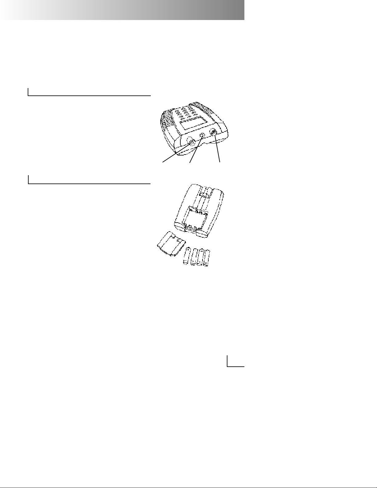
Electrode Connector Inputs
Twist-Lock: Used for attaching pH/ATC,
FET pH/ATC,conductivity/ATC cells or
ATC (temperature) electrodes with the
waterproof Twist-Lock connector.
BNC: Used for attaching pH,ORP,or ISE
electrodes with BNC connector.
Reference: Used for attaching a separate reference probe.
Batteries
The meter requires four AA alkaline batteries (unless used with the optional
Power or Docking Station).To install batteries, slide the compartment cover open
by pressing in and down where indicated.Position the batteries according to
the directional markings and insert.Slide
the cover closed.
Note: Nickel-cadmium rechargeable
batteries can be used,but their
operating life is half that of alkaline
cells, and they cannot be
recharged in the meter.
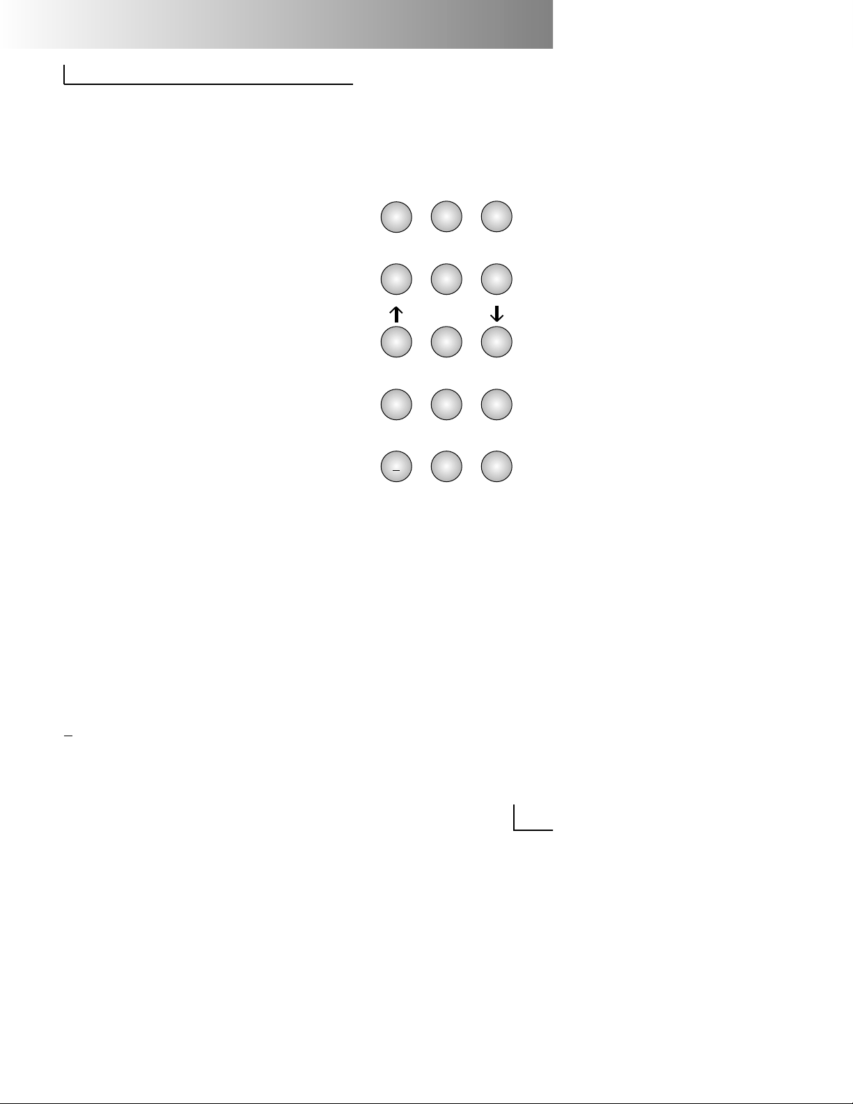
LCD Display
BNC
Reference Twist-Lock
1
Page 6
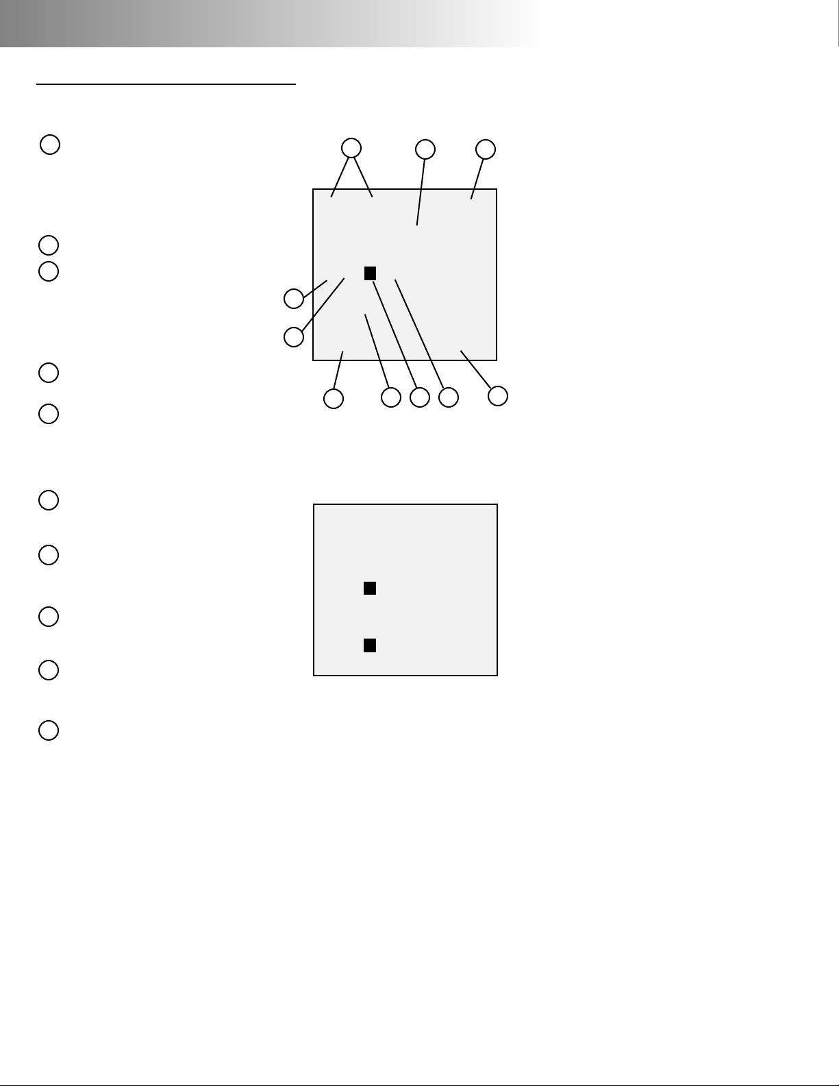
Note: Not all of the following will display at the same time.
Temperature: The meter displays
the measured temperature when
an electrode with ATC or separate
temperature probe is attached.
Shows M when a manually entered
temperature is being used.
Result: Current measurement.
BAT: Indicates that the meter has
10% of battery life remaining
(approximately 4 hours),or AC
indicates that the meter is connected to the Docking or Power
Station.
Channel: Indicates result is from A
(Twist-Lock input) or B (BNC input).
Manual Temperature: M indicates
that measurement is using a manually entered temperature in place
of the automatic temperature.(See
page 13).
Date: The meter displays the current date,either in mm/dd/yy or
dd/mm/yy format.
Buffers/Standards: Shows individual
buffers or standards that have
been entered.
Stability symbols: S indicates the
reading is stable,U indicates an
unstable reading.
Mode: Indicates the meter is in pH,
mV, ion, rel mV,conductivity,resistivity,salinity or TDS mode.
Time: Displays the current time in
either 12 hour AM/PM or 24 hour
format.
Function Keys
A
M 25.0°C
BAT
7.000
A M pH
4.00
7.00
10.00
1/24/97 11:52 AM
S
G
A
I
F
D
J
C
B
E
H
B
C
D
E
F
G
H
I
J
Single Channel Display
21.3°C
7.000
A pH
1.00
B M mg/L F1/24/97 11:53 AM
Dual Channel Display
S
S
Page 7
mode: Selects the mode (pH,mV, ISE
temperature,conductivity,resistivity,salinity,or TDS) to use for the
currently selected channel (electrode input).
std: Initiates standardization process
for the currently selected mode to
enter pH buffers, ion standards or
conductivity standards.
channel: Selects the channel(s) (electrode
inputs) to display.
slope: Displays buffers or standards and
calibration data in slope display.
Press data to see the time and
date for each calibration point.
print: Outputs the current result or cali-
bration data to the Docking
Station RS232 interface and the
internal datalog.
setup: Calls the setup menu (see Setup).
Up/Down Scrolls when viewing stored data
Arrows: and sets the display contrast.
data: Enters the datalogging menu
(see Datalogging).
enter: Accepts numeric values,menu
selections or pending operations.
on/off: Turns the meter on and off.
clear: Clears an incorrect number entry
or cancels the current operation.
Numeric Enters number s for menu selec-
Keypad: tion, standard entry and other
operations.
+ Enters a negative value.
•: Enters a decimal point.
10X: Enters the exponential part of a
number.
1
4
7
2
5
8
3
6
9
0
+
.
10
x
mode
std channel
slope
print setup
data
enter
on/off
clear
3
Page 8
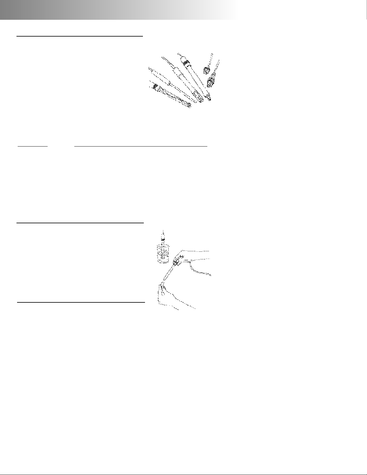
Electrodes
The meter allows you to use a variety of
glass membrane (“glass”) pH/ATC electrodes,ion selective electrodes,the Field
Effect Transistor (FET) Solid-State pH/ATC
electrode (PHH-925 only),temperature
(ATC) probes,Conductivity/ATC cells (AP50
only),combination electrodes using a BNC
connector,or separate electrode pairs with
BNC connector and reference pin.The
glass pH,FET pH and conductivity cells with
Twist-Lock connector are automatically
detected and identified by the meter.
Preparing pH and Ion Selective Electrodes
Remove the protective end cover or the
soaker bottle from the electrode.Before
first using your pH electrode or whenever
the electrode is dry,soak it several hours in
an electrode filling or storage solution (4
Molar KCl solution) or in a buffer for pH
electrodes.Store and condition ISE’s in the
recommended solutions.
Preparing Conductivity Cells
Remove the protective end cover from the
cell.Rinse the cell with deionized or demineralized water.
To measure Use channel (connector)
pH A (Twist-Lock)
or
B (BNC)
ORP (mV) B (BNC)
FET pH A (Twist-Lock)
ISE B (BNC & Reference)
Conductivity A (Twist-Lock)
pH & ISE A (Twist-Lock pH)
and
B (BNC ISE)
pH & Conductivity A (Twist-Lock Cond.)
and
B (BNC pH)
Page 9
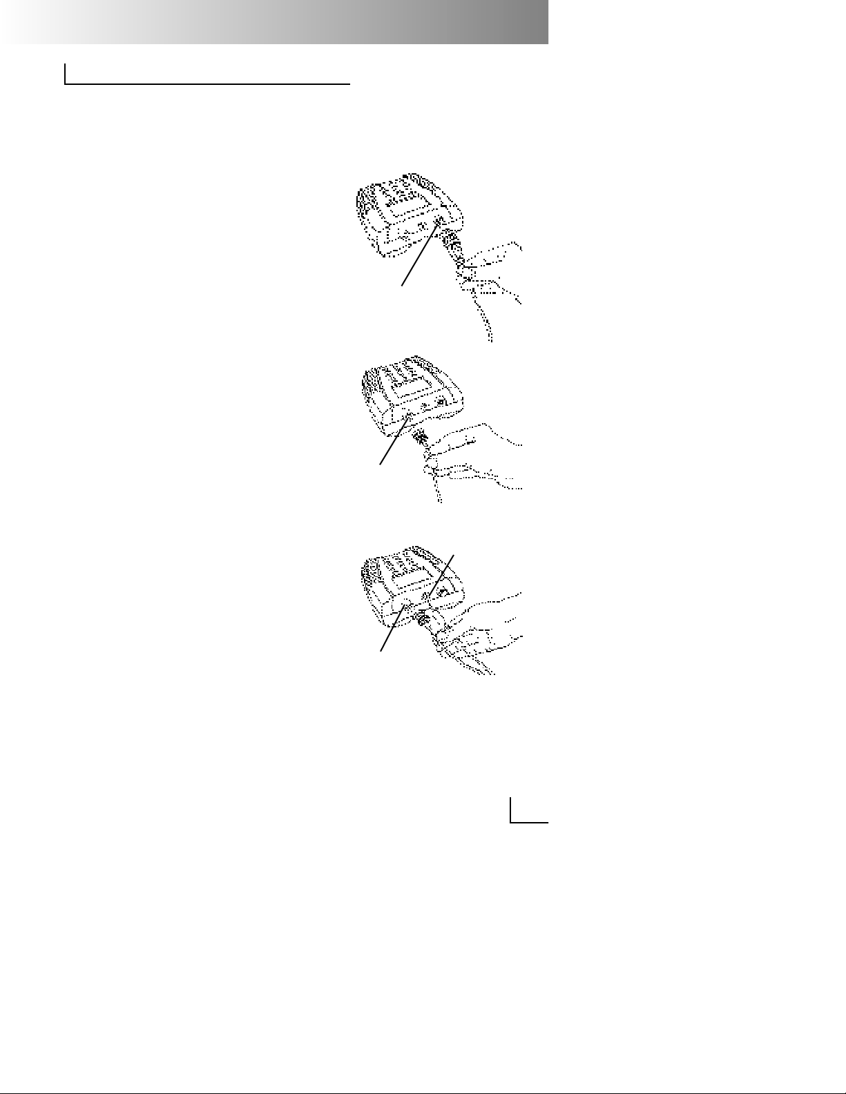
Connecting Electrodes
Note: If you install an electrode with a
Twist-Lock connector,the meter
automatically senses it and selects
the appropriate mode and standardize menus for that type of
electrode.
Glass pH/ATC, FET pH/ATC electrode, conductivity/ATC cell or ATC Probe (with
Twist-Lock connector):
Connect the electrode to the Twist-Lock
input located at the top of the meter.Line
up the white arrow and line on the electrode’s Twist-Lock connector and push
until it locks in place.To disconnect,twist
the connector ring in the arrow direction
and pull apart.
pH, ORP or ISE electrode (with BNC connector):
Connect the electrode to the BNC input
located at the top of the meter.Push in
and rotate the electrode’s BNC connector until it locks in place.To disconnect,
twist the BNC connector in the opposite
direction and pull.
Electrode Pair Using a Reference
Electrode (with Reference Pin Plug):
Connect the indicating electrode to the
BNC input.Connect the reference electrode to the Reference input.Push the
electrode’s tip pin plug into the input to
connect and pull out to disconnect.
BNC
Input
Twist Lock
Input
5
BNC
Input
Reference
Input
Page 10

Using and Storing Electrodes
pH Electrodes
Provide moderate stirring for faster
electrode response.
Rinse the electrode between each
measurement with a portion of the
next sample or buffer to be measured,
or with deionized or distilled water.
Keep glass electrodes wet when not
being used by moistening the cotton in
their end covers with electrode filling
solution and storing them with end
covers on,or by placing in their storage vials.
Keeping glass electrodes “wet”will
improve their performance.In the la b,
store electrodes in electrode filling solution or storage solution (4M KCl).For
electrodes used in field applications,
occasionally leave them in solutions for
several hours.
Solid-State FET Electrode
The model PHH-925 allows use of both
standard glass pH/ATC and Solid-State
FET (Field Effect Transistor) pH/ATC electrodes.The meter can store a calibration for both types of electrodes.Plug
the FET electrode into the Twist-lock
input. Allow the FET about 2 minutes to
warm up and stabilize when first connected.The FET electrode can be
stored dry or in electrode storage solution.If the FET electrode remains connected to the meter (and batteries are
in the meter),further warm up is not
necessary.
Page 11

Ion Selective Electrodes
Add proper amount of Ionic Strength
Adjuster (ISA) to all standards and
samples.
Provide moderate stirring for faster
electrode response.
Rinse the electrode(s) between each
measurement with a portion of the
next sample or standard to be measured,or with deionized or distilled
water.
In the lab, follow the instruction sheets
for the individual electrode.Store as
recommended.
Conductivity Cells
Rinse the cell between each measurement with a portion of the next sample
or standard to be measured.
Immerse the cell fully into the standard
or sample to be measured,lift the cell
to allow the solution inside the cell to
drain,and immerse the cell again.
Repeat three times.
Stir briefly and tap the cell against the
container bottom to dislodge air
bubbles.
Clean any deposits from the cell body
by rinsing with deionized water and
store dry.
7
Page 12

Setup Menu
Press setup to access the menu options.
1. Check batter y - Indicates the battery power remaining.
2. Set sleep mode - Enter the time in
minutes before the meter automatically turns itself off (“sleeps”) if
no keystrokes have been pressed.
Enter a value of 0 to keep the
meter on continuously. The maximum time allowed is 999 minutes.
3. Set sample ID# - Select a starting
value for the sample ID number.
Sample measurements will then
be identified by sequential sample
ID numbers. Each time the print
key is pressed the sample number
will be incremented.
4. Set time and date - Enter time and
format,and date and format.
5. Signal averag ing - Set the meter
to very slow (10 readings),slow
(8),medium (6),fast (4) and very
fast (2).The meter places each
new reading into a moving window,from which it calculates the
average (displayed) and standard
deviation (for stability determination).
6. Manual tempera ture - Enter a temperature to be used in the
absence of an ATC probe or with
manual temperature override.
7. Set contrast - Adjust the display
contrast.
8. Pr inter baud rate - Select the baud
rate for the RS232
input/output.
Pressing a number key causes that menu
selection to be chosen or that operation
to be executed.
Setup Menu
1 - Check battery
2 - Set sleep mode
3 - Set sample ID#
4 - Set time and date
5 - Signal averaging
6 - Manual temperature
7 - Set contrast
8 - Printer baud rate
Page 13

pH Standardization Menu
Press mode and select 1 – pH. Press std
and the standardize pH menu appears:
1. Enter a buffer - Allows you to add
a new buffer or update an existing
buffer.Follow the prompts.
2. Clear buffers - Clears all buffers
currently stored.
3. Select buffer set - There are five auto-
recognition buffer sets,one custom
set and manual entry
available.For some buffer sets the
meter will ask for the nominal reference temperature for the buffers set
(the temperature at which the
buffers are at their nominal values;
e.g.,7.000 at 25°C).
Auto-recognition buffer sets - The
five buffer sets are automatically
recognized and temperature corrected for the variation of buffer
pH with temperature.
Custom buffers - Allows you to
enter up to five custom buffers
(each at least two pH units
apart), with no temperature compensation.
Manual entry - Allows you to enter
any buffer value.
4. Enter slope - Allows you to enter a
known slope to be used by the meter
with a single-point standardization.
The normal default slope is 59.16
mV/pH.The meter allows between 80
and 120 % efficiency to be entered.
5. Temperature source - Allows the
meter to be set to use the ATC if pre-
sent (Auto) or use a manual temperature override (Manual).
6. Set isopoint - Allows you to enter in an
isopotential point (See Appendix F).
7. Resolution - Allows pH readings to be
set to 0.1,0.01,or 0.001 pH units.
9
Auto-recognition
Buffer Sets
• 2, 4, 7, 10,12
• NIST 1.68,4.01,6.86,
9.18,12.46
• 1,3,6,8, 10, 13
• DIN 1.09,3.06,4.64,
6.79,9.23,12.75
• 1,4,7,10, 13
• Custom buffers
Standardize pH
Channel A
1 - Enter a buffer
2 - Clear buffers
3 - Select buffer set
4 - Enter slope
5 - Temperature
source
6 - Set isopoint
7 - Resolution
Note: Dur ing auto-
matic calibration,the
meter allows pH
electrodes with 90 to
105% efficiency to
be used.
Page 14

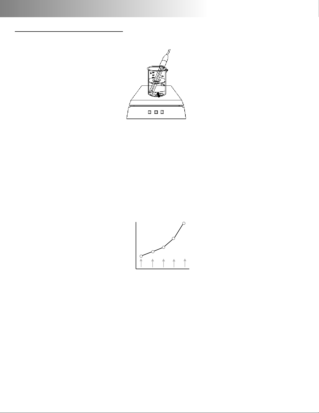
Standardizing and Measuring pH
1. Immer se the electrode in a buffer
and stir moderately.The meter displays the current pH measurement.
2. Press std, then press 1–Enter a buffer.
3. Follow the prompts on the display.
4. The meter automatically recognizes
the buffer,waits for a stable signal,
and enters the buffer. The entered
buffer appears in the display.
5. Alternatively,if the signal is not stable,you can press enter when the
reading stabilizes according to your
tolerance criteria.The meter then
enters the buffer.
6. Repeat steps 1 through 3 to enter a
second,third,fourth or fifth buffer.
With more than one buffer the
meter performs a diagnostic check
on the electrode.The electrode is
considered good if the slope is
between 90 to 105%.If a sixth buffer
is entered,the buffer farthest away is
replaced by the new buffer.
Hints: To achieve better accuracy:
• Standardize using at least two buffers ,
bracketing the expected pH of your
samples.
• Standardize at least daily for the most
accurate readings.
• Rinse the electrode with DI water
between samples and buffers.
• Blot the electrode dry (DO NOT rub or
wipe) between samples and buffers.
• Stir all buffers and samples.
• During standardization,allow time for
mV
4 7 10
pH buffers
samples
Page 15

the electrode to stabilize before entering the buffer into the meter.
• Always use fresh buffers .
Clearing Buffers
Press std, then press 2–Clear buffers to
clear buffers. If all previously entered
buffers will be re-entered,it is not necessary to clear buffers.If re-entering only
some buffers, all the old buffers should be
cleared.
The meter automatically compensates for
the temperature dependence of the
electrode’s response when measuring pH.
The meter also compensates for buffer ‘s
change in pH value with temperature.
Temperature compensation is based on
temperature either from an ATC probe or
a manually entered temperature.
11
Actual Buffer pH vs. Temperature
pH 4.00(4.01)/7.00/10.00 buffer (nominal 25°C)
Temperature Buffer 4 Buffer 7 Buffer 10
(°C)
30 4.016 6.991 9.947
25 4.008 7.003 10.000
20 4.003 7.020 10.057
15 4.000 7.042 10.119
10 3.998 7.069 10.187
Page 16

Millivolt measurements are used to measure ORP (oxidation-reduction potential)
or redox potential,to check performance of pH or Ion Selective Electrodes,
and for redox titrations.
The meter will measure millivolts (mV) by
selecting mV mode using the mode key.
Relative mV can be measured by entering a mV offset or using a mV value as
the relative mV reference point.
Relative mV Standardization Menu
In mV mode,press std and the standardize mV menu appears:
1. Auto-zero relative mV - Sets the relative mV offset equal to the negative of the current mV reading. The
current mV becomes 0.0 relative
mV.
2. Enter manual mV offset - Allows you
to enter in any mV offset.
3. Clear relative mV mode - This
clears any offset that has been
entered,returning the meter to
absolute mV mode.
4. Resolution - Allows mV readings to
be set to 1 or 0.1 millivolt.
Clearing Relative mV Mode
Press std,then press 3 – Clear relative mV
mode to clear offset and return the
meter to absolute mV mode.
Standardize mV
Channel A
1 - Auto-zero
relative mV
2 - Enter manual
mV offset
3 - Clear relative
mV mode
4 - Resolution
Electrode Potential,mV
Titrant Volume, mL
Redox Titration
Page 17

The PHH-925 and PHH-950 can be used
with Ion Selective Electrodes (ISE’s) to
directly read ion concentrations.ISE’s are
connected to the channel B (BNC) input.
If a separate reference electrode is
required,connect it to the reference
input jack.
Ion Standardization Menu
Select channel B using the channel
key. Press mode and then press 3–ISE
for ion concentration mode.Press std
and the standardize menu appears.
1. Enter a standard - Allows you to
add a new standard or update
(re-enter) an existing standard.
Follow the prompts.With the first
standard you select the ion
name and units.
2. Clear standards - Clear s standards
for the standardization set in current
use.
3. New ion cal - Allows for another set
of calibration standards to be
entered/stored for a different ISE.
The meter stores up to five ion calibrations.
4. Recall ion cal - Allows the recall of
an ion calibration set.
5. Enter slope - Allows entry of a known
slope to be used with a single-point
standardization.The nor mal default
slope is 59.16 mV/decade for monovalent ions and 29.58 mV/decade
for divalent ions at 25°C.
6. Temperature source - Allows the
meter to use the ATC (if present) or
a manually entered temperature
override*.
7. Set Isopoint - Allows you to enter an
isopotential point (See Appendix F).
8. Enter blank - Allows you to enter a
blank.
9. Resolution - Allows the readings to
be set to 1,2 or 3 digits.
Standardizing and Measuring Ion
13
Standardize ISE
Channel B
1 - Enter a standard
2 - Clear standards
3 - New ion cal
4 - Recall ion cal
5 - Enter slope
6 - Temperature source
7 - Set isopoint
8 - Enter blank
9 - Resolution
*Temperature Source
Set to Auto to use the
ATC probe (if present).
Set to manual when
samples being measured on one channel
are at a different temperature from samples
with the ATC probe.Use
manual when temperature correction is not
desired or the isopotential is not known (ISE’s).
Page 18
1. Add the appropriate Ionic Strength
Adjuster (ISA) solution to the standard.
2. Immer se the electrode(s) in the solution and stir continuously.
3. Press std and select 1–Enter a stan-
dard to add a standard.
4. Follow the prompts.
5. The meter waits for a stable signal
and enters the standard.The
entered standard appears in the
display.
6. Alternatively,if the signal is not stable,you can press enter when the
reading stabilizes according to your
tolerance criteria.The meter then
enters the standard.
7. Repeat steps 1 through 6 to enter a
second,third,fourth or fifth standard.
With more than one standard,the
meter performs a diagnostic check
on the electrode.
Helpful Hints:
• Provide stirring.
• Allow the electrode time to reach a
stable reading before entering the
standard into the meter.
• To achieve better accuracy,standardize
using at least two standards,bracketing
the expected range of your samples.
• Standardize from low to high concentrations.
• Always use fresh standards.
Clearing Standards
mV
ion standards
log [ion]
Page 19

Press std, then press 2–Clear standards
to clear the current set being used.
This will not clear other stored ion calibrations.
The meter will automatically recognize
when a conductivity cell is attached
to the meter.
Select channel A using the channel
key. Pressing mode allows the meter
to be set to the proper units.
Conductivity modes and units are:
Conductivity - µS/cm or mS/cm.
Resistivity - Ω•cm , kΩ•cm or MΩ•cm
Practical Salinity - salt concentration
in parts per thousand (ppt) based
upon sea water.
NaCl Salinity - sodium chloride equivalent concentration in ppt.
Total Dissolved Solids (TDS) - an empir ical scale relating conductivity to total
dissolved solids in ppt.
Conductivity Standardization Menu
Press std and the standardize conductivity menu appears:
1. Enter standard - Allows you to
add a new standard or re-enter
an existing standard.Up to five
points may be entered.Follow
the prompts.
2. Clear standards - Clears all standards currently stored.
3. Temperature source - Allows the
meter to use the ATC (if present),
or use a manually entered temperature override.
4. Enter known cell constant - Allows
you to enter the nominal or known
actual cell constant.
5. Enter tempera ture coefficient -
15
Select Mode
Channel A
1 - Conductivity
2 - Practical
Salinity
3 - NaCl Salinity
4 - Resistivity
5 - Total Dissolved
Solids
6 - Temperature
Standardize
Conductivity
Channel A
1 - Enter a standard
2 - Clear standards
3 - Temperature
Source
4 - Enter known
cell constant
5 - Enter temperature
coefficient
6 - Resolution
7 - Autoranging
Page 20

Allows you to select the reference
temperature and the temperature
coefficient (used with conductivity).
The default setting is 1.90%/°C correction to 25°C.
6. Resolution - Allows the readings to be
set to 1,2,3 or 4 digits.
7. Autorang ing (Conductivity/
Resistivity modes)- Select unit
autoranging (µS to mS,Ω to kΩ to
MΩ) or fixed units (µS,KΩ).
or
7. Solids factor (TDS mode) - enters the
solids factor used for TDS.The default
is 0.5.
Standardizing and Measuring
Conductivity, Salinity, Resistivity or TDS
1. Immer se the cell in a standard and
stir moderately.The meter displays
the current measurement.
2. Press std, then press 1 – enter stan-
dard to add or re-enter a standard.
Follow the prompts.
3. The meter waits for a stable signal,
and enters the standard.The entered
standard appears in the
display.
4. Alternatively,if the signal is not stable,
you can press enter when the reading stabilizes according to your tolerance criteria to enter the standard.
5. Repeat steps 1 through 3 to enter a
second,third,fourth or fifth standard.
Standards must be at least two-fold
apart in value.On each standard,
the meter performs a diagnostic
check on the cell.The cell is considered bad if the cell constant is outside 50% and 200% of the nominal
Page 21

value.
Helpful Hints:
• Always immerse,then drain, the conductivity cell several times when
transferring to a new standard or
sample.
• Ta p the cell gently to remove air bubbles.
• Always use fresh standards.
• Standards are entered in conductivity as µS/cm,in resistivity as KΩ•cm,
and in salinity and TDS as either
µS/cm or KΩ•cm.
• To achieve better accuracy, standardize using at least two standards,
bracketing the expected range of
your samples.
• Verify that the proper cell constant is
being used for the sample’s conductivity (1 or 10 cm-1).
Clearing Standards
1. Press std,then press 2 – Clear standards.
Temperature Compensation
The meter automatically compensates
for conductivity temperature dependence when a temperature coefficient
is used.The range of values for the temperature coefficient is from 0 to 4%/°C.To
disable temperature compensation,
enter a value of zero.Resistivity is not
temperature compensated,practical
salinity is referenced to 15°C,and NaCl
equivalent salinity is referenced to 25°C.
For conductivity measurements,select a
reference temperature and enter a temperature coefficient.
Determining Temperature Coefficients
17
Conductivity
Concentration
Page 22

The temperature coefficient of a particu-
lar sample can be determined and
entered to allow temperature correction.A typical temperature coefficient
for a simple salt solution is 1.9%/°C.
To determine temperature coefficient:
• Set reference temperature to 25°C
and temperature coefficient to
0.00%/°C.
• Record the conductivity value and
temperature of the solution (temperature must be different than the reference temperature).
• Heat or cool solution to the reference
temperature.
• Record the conductivity of the solutions at the reference temperature.
• Solve the following equation for the
temperature coefficient TC.
Datalogging
TC =
Conductivity at T
Conductivity at T
ref
–1
100
T – T
ref
Typical Temperature Corrections for 15°C to 25°C
NaCl Concentration (M) TC (%/°C)
0.5 1.90
0.1 1.96
0.01 2.01
0.001 2.02
KCl
1 1.75
0.1 1.85
0.01 1.90
0.001 1.96
Page 23

Data
toggles
between
these
screens
The meter will store up to 250 data
points. Press print to store the current
result with units,temperature,time,
date,channel,sample number and
stability to the internal datalog. Print
also outputs an ASCII text string with
the information to the optional
Docking Station RS-232 interface.
Press data and the Datalogging
menu will appear.
1. Star t interval - Allows you to
enter the time interval for automatic datalogging.
2. Stop interval - Stops time-based
datalogging.
3. View datalog - Shows the stored
data,one screen at a time.Press
the data key to move side to
side to show time and date for
each sample.Use the arrow keys
to scroll up and down through
the samples.
4. Clear da talog - Clears all the
data points out of memory.
5. Pr int datalog - Allows you to print
all data points.
The optional Power Station provides a
laboratory bench stand and external
19
Minimum Datalogging
Time Interval
With meter continually on:
1 second at 9600 baud
2 seconds at 2400 baud
With meter in sleep mode:
10 seconds
Datalogging
(43 points)
1 - Start interval
2 - Stop interval
3 - View datalog
4 - Print datalog
5 - Clear datalog
View Datalog
(243 points)
5.432 pH A S
#12345 M 25.4C
9.99E-9 mg/L F- B S
#345 100.0C
180.5 mV B S
#3 34.5C
9.500 ion Cl- A S
#12345 100.2C
100.2 µS/cm A U
#12400 55.2C
screen data
View Datalog
(243 points)
5.432 pH A S
5:43PM 12/30/95
9.99E-9 mg/L F- B S
5:43PM 12/30/95
180.5 mV B S
5:43PM 12/30/95
9.500 ion Cl- A S
5:43PM 12/30/95
100.2 µS/cm A U
5:43PM 12/30/95
screen data
Page 24

AC power.The optional Docking Station
provides external AC power and RS-232
interface to a printer or computer/terminal.
Installing Meter in the Station
1. Connect the power supply to the
Power or Docking Station and to
an AC outlet.
2. Place the meter in the station.
3. The meter displays AC to indicate
external AC power is being used.
The Auto-Off feature is suspended
while the meter is in the
station.
Using with a Printer or
Computer/Terminal
1. Connect your serial ca ble from
the Docking Station to the serial
port on your printer or computer/
terminal. See the next page for
wiring requirements.
2. Set pr inter as follows:
• baud rate must match the
meter
• 8 data bits
• no parity
• 1 stop bit
3. Pressing pr int causes the current
reading to be printed.
Note: During standardization,the
meter automatically prints standardization data,including the value,
temperature,slope and the time
and date.
The following serial interface
commands are available:
Add standard: 7.ØØ3 pH B 25.ØC 2/17/97 11:47 AM
Add standard: 4.ØØ9 pH B 25.ØC 2/17/97 11:47 AM
Add standard: 1Ø.ØØØ pH B 25.ØC 2/17/97 11:47 AM
4.ØØ9 mS/cm 2/17/97 11:47 AM 25.ØC 99.8
7.ØØ3 mS/cm 2/17/97 11:47 AM 25.ØC 99.7
1Ø.ØØØ mS/cm 2/17/97 11:47 AM 25.ØC
Sample: 1S 1Ø.ØØ1 pH B 25.Ø M 2/17/97 11:48 AM
Add standard: 1.ØØ ppm Cl- B 25.ØC 2/17/97 11:48 AM
Add standard: 1ØØØ ppm Cl- B 25.ØC 2/17/97 11:49 AM
Add standard: 1ØØ ppm Cl- B 25.ØC 2/17/97 11:49 AM
Add standard: 1Ø.Ø ppm Cl- B 25.ØC 2/17/97 11:49 AM
Sample: 2 S 1Ø.Ø ppm Cl- B 25.ØCM 2/17/97 11:50 AM
Clear standards: cond A
Add standard: 1ØØ uS/cm A 25.ØC 2/17/97 11:52 AM
Sample: 3 S 1ØØ uS/cm A 25.ØC M 2/17/97 11:52 AM
Sample: 4 S 1Ø.Ø kOhm CM A 25.ØC M 2/17/97 11:52 AM
Sample: 5 U 1.ØØ kOhm CM A 25.ØC M 2/17/97 11:52 AM
Page 25

Command Function
KM Mode
KS Standardize
KC Channel
KL Slope
KP Print
KT Setup
KA Up Arrow
KD Data
KB Down Arrow
KN Enter
KO Off
KX Clear
KF ±
KG Decimal Point
KE 10
x
K(digit) Enter numeric dig it
The complete pin connections for the digital I/O connector to the docking station
are below.
Note: Some printers and computer
serial ports will require only pins
1-3 connection.Those requir ing
more extensive handshaking
may require the other pin connections.
Testing the Electrode and Meter
21
Docking Pin At
Station Function Computer
1 common 1
2 serial data in 2
3 serial data out 3
4 no connection 4
5 no connection 5
6 no connection 6
7 common 7
8 common 8
9 no connection 9
Page 26

To test the pH electrode,place it in a fresh
pH 7 buffer.Select the correct channel for
the electrode.Press mode and select mV.
Verify that the meter is in absolute mV
mode (display shows mV,not rel mV) and
note the mV reading.Repeat for either a
pH 4 or pH 10 buffer.If the electrode
potential is within the limits shown,it is
measuring correctly.
pH 7 0 ± 30 mV
pH 4 159 to 186 mV higher than pH 7 reading
pH 10 159 to 186 mV lower than pH 7 reading
To test the meter for correct operation
with a BNC electrode,short the BNC input
connector using a bent paper clip as
shown.Press mode and select mV mode.
If the meter reads 0 ± 0.1 mV*, it is measuring correctly.
To test the meter for correct operation
with a pH Twist-lock electrode,shor t the
Twist-lock input connector using two
paper clips as shown.Each paper clip
must touch two adjacent pins inside the
connector.Press mode and select mV
mode.If the meter reads 0 ± 0.1 mV*, it is
measuring correctly.
* Note: Meter accuracy is ±0.1 mV at
calibration temperature,not including
long term drift and a temperature
error.The zero and slope temperature
coefficients of the meter over the
range of 15 to 40°C specify ±4 mV at
full scale (worst case).The long ter m
drift will not exceed 0.1 mV per month.
Error Messages
Page 27

pH value out of range
The electrode efficiency is outside the
acceptable limits for the pH electrode: 90
to 105%.
The electrode has drifted too far from the
last calibration.
• pH electrode is not in a solution.
• Insufficient or incorrect filling solution
in reference electrode.
• Cracked or broken glass bulb membrane.
• Improper electrode conditioning.
• Bad buffers.
• Blocked or clogged reference electrode liquid junction.
• Poor technique not rinsing electrodes
between buffers.
• Loose connector or cable.
• Incorrect manual buffer value entry.
• Defective meter.
mV value out of range
• Electrode is not in a solution.
• Defective electrode.
• mV input exceeds the design range
of the meter.
• Defective meter.
Ion value out of range
The electrode slope is outside the
acceptable limits for an ion selective
electrode.
• Ion electrode is not in a solution.
• Bad standards.
• Entry of incorrect concentration.
• Poor technique,not rinsing electrodes between standards.
• Not stirring the standards.
• Improper electrode conditioning.
• Defective ISE or reference electrode
• Insufficient or incorrect filling solution
23
Page 28

in reference electrode.
• Loose connector or cable.
• Defective meter.
The ion standard (mV signal) is too close to
another standard.
• The standards are made too close
together (should be 10 fold apart).
• Bad standards.
• There is no ISA adjuster in the standards.
• Defective ISE or reference electrode.
• Insufficient or incorrect filling solution in
reference electrode.
Conductivity out of range.
Resistivity out of range.
Salinity or TDS out of range.
• Sample too high in conductivity for
meter range with cell constant used.
• Defective probe.
• Defective meter.
Temperature out of range.
• Defective ATC probe.
• Temperature manually entered outside of -5 to 105°C.
• Defective meter.
The meter has lost calibration coefficients.
• Battery backed memory has been
corrupted. (The memory does not use
the AA batteries for backup.There is a
separate lithium battery inside the
meter.It is
not
user serviceable).
• Factory service is required to re-calibrate the meter for accurate mV, temperature,or conductivity measurements. pH, ion or conductivity measurements are still accurate after standardization with buffers or standards.
pH Theory
Page 29

The measurement of pH plays an
important role in water quality, industry and research.pH is a measure of
acidity or alkalinity of a solution,and
is usually written:
pH = -log [H+]
Where [H+] is the concentration of
hydrogen ions.
pH levels generally range from 0 to
14,with a pH value of 7 being the
neutral point.pH values above 7 are
alkaline,and pH values below 7 are
acidic solutions.
Conventional pH meters use a glass
pH electrode paired with a reference electrode.The reference electrode provides a stable reference
point and completes the electrical
circuit.The pH meter reads the voltage between the two electrodes,
converts it to pH units,and displays the
result.
The PHH-925 meter can also use a Field
Effect Transistor (FET) electrode for
measuring pH.The FET uses an ion-sensing solid state membrane attached to
a transistor to measure the hydrogen
ion concentration of a solution.
The measurement of ions plays an
important role in water quality, industr y,
25
pH
0 Strong Acid
1
2 Lemon Juice
3
4 Tomato Juice
5 Coffee
6
Neutral 7 Pure water
8 Baking Soda
9
10
11
12 Ammonia
13
14 Strong Base
More Acidic
More Basic
pH scale showing the
relative acidity or basicity of
some common substances
Page 30

research and environmental monitoring.Ionselective Electrodes (ISE’s) respond,more or
less exclusively, to a specific type of ion in solution.The par ticular ion to w hich an ISE
responds depends on the chemical makeup
of its sensing membrane.ISE’s operate according to a form of the Nerst equation:
E = Eo+ (2.303 RT/F) log a
Where:
E = measured electrode potential
E o= standard potential of the system (con-
stant)
R = gas constant
F = Faraday’s constant
T = absolute temperature
a = activity of the ion interest in the solution
Conductivity Theory
Page 31

Conductivity refers to the ability of a
solution to conduct electricity.The
amount of electrolytes present determine the ease with which a solution
can carry a current.
Conductivity is used as a measure of
the purity of water.Pure water contains
few dissolved ions and has a low conductivity and a high resistivity. Ultrapure
reagent grade waters are measured in
resistivity. Practical salinity is a measure
of salt concentration in sea water, NaCl
Salinity is the amount of NaCl dissolved
which would give the same conductivity as the sample,and Total Dissolved
Solids (TDS) is an empirical relationship
between conductivity and dissolved
solids in typical samples.
Isopotential Point
27
Conductivity =
1
Resistivity
TDS = Conductivity x Solids Factor
Where C = Conductivity
T = Temperature °C
Page 32

The Isopotential point is the potential of
an electrode system which does not
change with temperature.Typical pH
electrodes have isopotential points near
zero mV (which is the default setting for
the meter).For high accuracy pH measurements,or for ion measurements where
the sample temperature may widely vary,
the isopotential of the pH or ion electrode
may be experimentally determined and
entered into the meter.
• Prepare a set of buffers or ion standards spanning the linear range of
the electrode.Place the buffers or
standards in a temperature bath at
known temperature.
• Place the meter into mV mode.
• Measure and record mV readings of
each pH or concentration,and
repeat at several temperatures.
• Using graph paper,plot the log of
concentration or pH value versus
mV reading.
• Draw lines connecting the points at
each temperature.
Where the lines intersect is the
Isopotential point.
Page 33

29
200
100
0
10
-3
10
-4
Log of Ion Concentration, moles/L
Electrode
Output
(mV)
10°C
60°C
Isopotential Point:
3.07 x 10⁻⁴moles/L, 162 mV
Ion Electrode Isopotential Point
50
150
-180
0
180
4 7 10
pH
Electrode
Output
(mV)
25°C
10°C
Isopotential Point:
7.04pH 9 mV
pH Electrode Isopotential Point
Page 34

pH
Range: -2.000 to 20.000
Resolution: 0.1/0.01/0.001
Accuracy: ±0.002
mV
Range: ±1,200
Resolution: 1/0.1
Accuracy: ±0.1mV over ±400mV:
±0.2mV over ±1200mV
Zero temperature coefficient: 0.01 mV/°C max.
Scale temperature coefficient: 85ppm/°C max.
Ion
Range: 1.00E-9 to 9.99E9
Resolution: 1,2,or 3 significant figures
Accuracy: 0.17n%; where n equals electrons
exchanged in the electrode reaction
Conductivity
Conductivity 0.01 – 300,000 µS/cm*
Practical Salinity: 0 to 42 ppt*
NaCl equivalents: 0 to 70 ppt*
Resistivity: 33 to 100 megohms*
TDS: 0.005 – 300,000 ppt*
Resolution: 1, 2, 3 or 4 significant figures
Accuracy: ±0.5% of reading ±0.01 µS/cm
Temperature coefficient: 0.001 µS/cm/°C
with cell constant 1.0 cm
-1
Range 5: 30,000 to 3,000 µS/cm
Range 4: 3,000 to 300 µS/cm
Range 3: 300 to 30 µS/cm
Range 2: 30 to 3 µS/cm
Range 1: 3 to 0.3 µS/cm
Temperature
Range -5° – 105°C
Resolution 0.1°C
Accuracy ±0.3°C
* dependent on cell constant
Page 35

31
Maintenance
Other than battery replacement, this product contains no
user serviceable par ts . All replacement parts other than
batteries should be obtained from Omega Engineering Inc.
Cleaning
The exterior surfaces of this product may be cleaned with a
damp cloth or with mild detergent.
NOTICE
This equipment has been tested and found to comply with
the limits for a Class A digital device,pursuant to Part 15 of
the FCC rules. These limits are designed to provide reasonable protection against harmful interference when the
equipment is operated in a commercial environment.This
equipment generates,uses, and can radiate radio frequency energy and,if not installed and used in accordance
with the instruction manual,may cause harmful interference to radio communications.Operation of this equipment in a residential area is likely to cause harmful interference in which case the user will be required to correct the
interference at his own expense.
CAUTION
Changes or modifications not expressly approved by the
manufacturer could void the user’s authority to operate this
equipment.
!
Page 36

WARRANTY/DISCLAIMER
MEGA ENGINEERING, INC. warrants this unit to be free of defects in materials and
orkmanship for a period of 37 months from date of purchase. OMEGA Warranty adds an
dditional one (1) month grace period to the normal three (3) years product warranty to
over handling and shipping time. This ensures that OMEGA’s customers receive maximum
overage on each product.
the unit should malfunction, it must be returned to the factory for evaluation. OMEGA’s
ustomer Service Department will issue an Authorized Return (AR) number immediately upon
hone or written request. Upon examination by OMEGA, if the unit is found to be defective it will
e repaired or replaced at no charge. OMEGA’s WARRANTY does not apply to defects resulting
om any action of the purchaser, including but not limited to mishandling, improper interfacing,
peration outside of design limits, improper repair, or unauthorized modification. This
WARRANTY is VOID if the unit shows evidence of having been tampered with or shows evidence
f being damaged as a result of excessive corrosion; or current, heat, moisture or vibration;
mproper specification; misapplication; misuse or other operating conditions outside of OMEGA’s
ontrol. Components which wear are not warranted, including but not limited to
ontact points, fuses, and triacs.
MEGA is pleased to offer suggestions on the use of its various products. However,
MEGA neither assumes responsibility for any omissions or errors nor assumes liability for
ny damages that result from the use of its products in accordance with information proided by OMEGA, either verbal or written. OMEGA warrants only that the parts
manufactured by it will be as specified and free of defects. OMEGA MAKES NO OTHER
WARRANTIES OR REPRESENTATIONS OF ANY KIND WHATSOEVER, EXPRESSED OR
MPLIED, EXCEPT THAT OF TITLE, AND ALL IMPLIED W ARRANTIES INCLUDING ANY WAR-
ANTY OF MERCHANTABILITY AND FITNESS FOR A P AR TICULAR PURPOSE ARE HEREBY
ISCLAIMED. LIMITATION OF LIABILITY: The remedies of purchaser set forth herein are
xclusive and the total liability of OMEGA with respect to this order, whether based on con-
ract, warranty, negligence, indemnification, strict liability or otherwise, shall not exceed
he purchase price of the component upon which liability is based. In no event shall OMEGA
e liable for consequential, incidental or special damages.
ONDITIONS: Equipment sold by OMEGA is not intended to be used, nor shall it be used: (1) as
“Basic Component” under 10 CFR 21 (NRC), used in or with any nuclear installation or activity;
r (2) in medical applications or used on humans. Should any Product(s) be used in or with any
uclear installation or activity, medical application, used on humans, or misused in any way,
MEGA assumes no responsibility as set forth in our basic WARRANTY/DISCLAIMER language,
nd additionally, purchaser will indemnify OMEGA and hold OMEGA harmless from any liability
r damage whatsoever arising out of the use of the Product(s) in such a manner .
RETURN REQUESTS / INQUIRIES
irect all warranty and repair requests/inquiries to the OMEGA Customer Service Department.
EFORE RETURNING ANY PRODUCT(S) TO OMEGA, PURCHASER MUST OBTAIN AN
UTHORIZED RETURN (AR) NUMBER FROM OMEGA’S CUSTOMER SERVICE DEPARTMENT
N ORDER TO AVOID PROCESSING DELAYS). The assigned AR number should then be
marked on the outside of the return package and on any correspondence.
he purchaser is responsible for shipping charges, freight, insurance and proper packaging to
revent breakage in transit.
OR W
ARRANTY RETURNS, please have
he following information available BEFORE
ontacting OMEGA:
. P.O. number under which the product was
PURCHASED,
. Model and serial number of the product
under warranty, and
. Repair instructions and/or specific
problems relative to the product.
FOR NON-WARRANTY REPAIRS,
consult
OMEGA for current repair charges. Have the
following information available BEFORE
contacting OMEGA:
1. P.O. number to cover the COST
of the repair,
2. Model and serial number of product, and
3. Repair instructions and/or specific problems
relative to the product.
MEGA’s policy is to make running changes, not model changes, whenever an improvement is possible.
his affords our customers the latest in technology and engineering.
MEGA is a registered trademark of OMEGA ENGINEERING, INC.
Copyright 1996 OMEGA ENGINEERING, INC. All rights reserved. This document may not be copied, photocopied,
produced, translated, or reduced to any electronic medium or machine-readable form, in whole or in part, without
ior written consent of OMEGA ENGINEERING, INC.
Page 37

Where Do I Find Everything I Need for
Process Measurement and Control?
OMEGA…Of Course!
TEMPERATURE
MU
Thermocouple, RTD & Thermistor Probes, Connectors, Panels & Assemblies
MU
Wire: Thermocouple, RTD & Thermistor
MU
Calibrators & Ice Point References
MU
Recorders, Controllers & Process Monitors
MU
Infrared Pyrometers
PRESSURE, STRAIN AND FORCE
MU
Transducers & Strain Gauges
MU
Load Cells & Pressure Gauges
MU
Displacement Transducers
MU
Instrumentation & Accessories
FLOW/LEVEL
MU
Rotameters, Gas Mass Flowmeters & Flow Computers
MU
Air Velocity Indicators
MU
Turbine/Paddlewheel Systems
MU
Totalizers & Batch Controllers
pH/CONDUCTIVITY
MU
pH Electrodes, Testers & Accessories
MU
Benchtop/Laboratory Meters
MU
Controllers, Calibrators, Simulators & Pumps
MU
Industrial pH & Conductivity Equipment
DATA ACQUISITION
MU
Data Acquisition & Engineering Software
MU
Communications-Based Acquisition Systems
MU
Plug-in Cards for Apple, IBM & Compatibles
MU
Datalogging Systems
MU
Recorders, Printers & Plotters
HEATERS
MU
Heating Cable
MU
Cartridge & Strip Heaters
MU
Immersion & Band Heaters
MU
Flexible Heaters
MU
Laboratory Heaters
ENVIRONMENTAL
MONITORING AND CONTROL
MU
Metering & Control Instrumentation
MU
Refractometers
MU
Pumps & Tubing
MU
Air, Soil & Water Monitors
MU
Industrial Water & Wastewater Treatment
MU
pH, Conductivity & Dissolved Oxygen Instruments
M2831/0298
 Loading...