

Page 1
INSTRUCTION MANUAL
pH/mV
PHH-?
METER
52
Page 2

1.0
CONTENTS
OF
TABLE
GENERAL OVERVIEW..........3
PAGE
2.0
3.0
4.0
5.0
6.0
7.0
8.0
9.0
10.0
11.0
SPECIFICATIONS............3
INSTRUMENT FAMILIARITY....4
OPERATION
CALIBRATION
...............
............
MEASUREMENT GUIDELINES
pH
BUFFERS
ELECTRODE CARE
.............
.........
BATTERIES................1
TROUBLESHOOTING..........1
THEORY OF MEASUREMENT....1 2
WARRANTY.........BAC K COVER
...6
...7
.
...8
...9
..s
0
1
Page 3

This
solutions.
necessary
measurements,
meter measures
The meter includes all the functions
for
precise
including set and slope knobs for two
or three point calibration,
the
and
pH/MV
accurate
a manual temperature
of
pH/MV
adjustment allowing for temperature compensation,
31/z
and a
digit LCD display.
Re-chargeable batteries and an AC adapter/re-
charger allow versatility for use in the field and
in the lab.
The batteries will last approximately
400 hours before re-charging is required. The LCD
display will
give a
"BAT"
reading
when
batteries are low.
2.0
SPECIFICATIONS
most
the
READOUT
RANGE
ACCURACY
RESOLUTION
TEMP. COMP.
TEMP. RANGE
SIZE
WEIGHT
POWER
.5"
3112
O-14
+0.02
tall Digit LCD
51999
/
pH
/
pH
/
1 pH5.1
mV
mV+2
mV
MANUAL
O-
6"H
1ooOc
3"W
2Oc
+
2%
l.S'Lbs'(0.7Kg)
8
"AA"
Rechargeable Batteries
3
Page 4

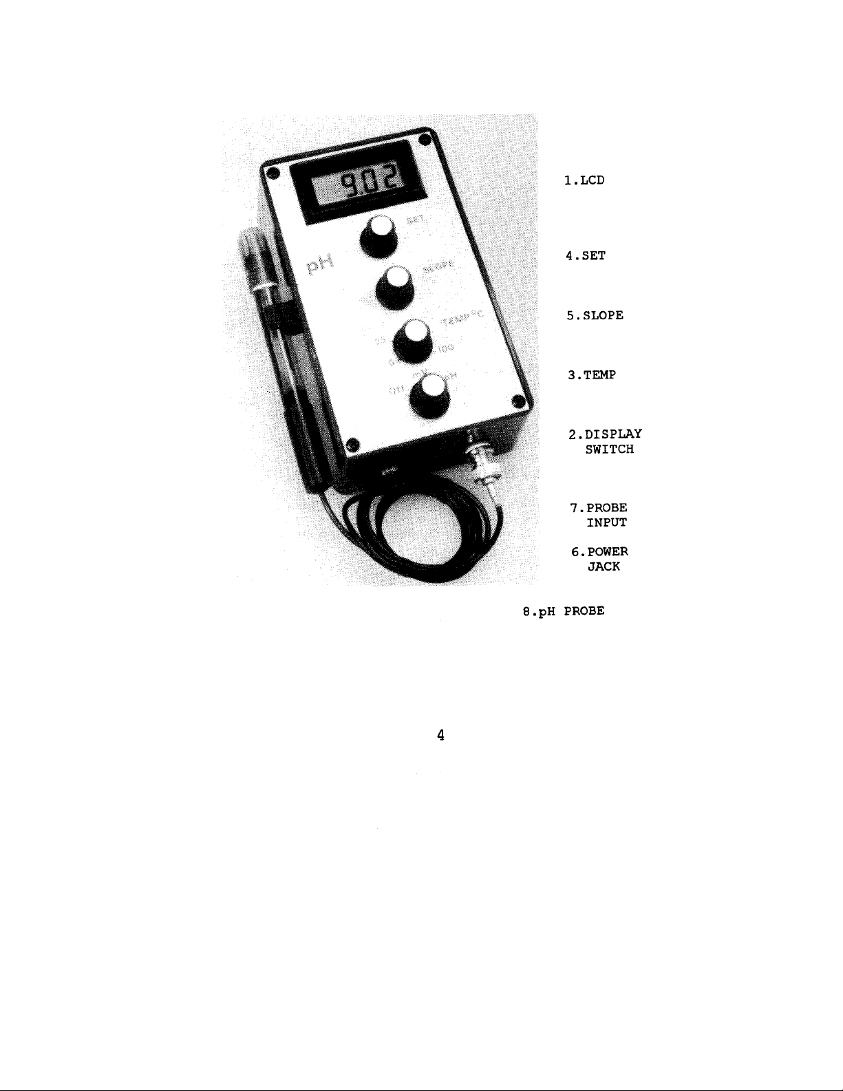
l.LCD
4.SET
5.SLOPE
3.TEMP
2.DISPLAY
SWITCH
7.PROBE
INPUT
6.POWER
JACK
8.pH
PROBE
4
Page 5
3.0
INSTRUMENT FAMILIARITY
1.
2.
3.
4.
5.
6.
Liquid Crystal Display
pH/MV
l/2
digit display for
3
Display Switch
Selects the
Temp
'k
MV
or the
pH
readings.
function.
Used for temperature compensation in the
function.
Set the dial to the temperature
of the sample being measured.
Set
pH
7.00 adjustment knob. Calibrates the
offset of the
pH
meter. Corrects for
variations in the probe as it ages,
Slope
pH
pH
4 or
10 adjustment knob.
the gain of the
value.
Corrects meter for variations in the
pH
meter for a known
Calibrates
probe as it ages.
Power Jack
The wall plug adaptor output is attached to
operate from line voltage.
Input is
5oomA.
pH
pH
12vdc,
7.
pH
Probe
Inpu t
A BNC connector for the
8.
pE
Probe
(Standard with Field Kit)
Standard single junction, combination
electrode.
5 inches long,
4.0
1.
OPERATION
The meter
chargeable batteries.
The body is
and has a six foot cable.
is.powered
with internal NICAD re-
Connecting the AC adaptor
will re-charge the batteries while
5
pH
probe.
l/2
inch diameter,
allowing
Page 6
continued
operation.
The batteries
charged overnight prior to the inital use of the
meter on battery power only.
pH
2.
Attach the
probe to the BNC connector.
should be
3.
Set the
Function
switch to the
position.
4.
Calibrate the meter as described in the
CALIBRATION section.
5.
6.
Insert the probe into the unknown solution
at least
l/2
inch.
Allow the display to settle and record the
reading.
5.0
CALIBRATION
1.
Attach the
2.
Set the
pH
probe to the BNC connector.
switch to the
position.
TEMP
3. Adjust the
knob to the temperature of
the buffer.
pH
4. Place
electrode in
Sufficient buffer should be used to
pH
immerse the
tip.
pH
7 buffer.
mV
MV
or Function
or
pIi
pH
5. Adjust the SET knob to read
pH
7.00 on the
display.
6. Rinse the electrode with distilled water.
7. Immerse the electrode in a second standard
pH
buffer,
either
pH
4.00 or
10.00.
time for the probe to equilibrate.
6
Allow
Page 7

8.
Adjust the SLOPE knob to read 4.00 or
10.00 depending on the second buffer used.
9.
Rinse the electrode.
For a three point calibration, repeat
10.
steps 8 thru 10, using the buffer not
previously used.
11.
The meter is now ready for use.
pH
Note :
The calibration of a
meter is not permanent.
It should be done on a regular basis, or any time
the
pH reading response becomes
erratic.
6.0
MEASUREMENT
GUIDELINES
slow
and or
.Avoid
1
solutions.
after each measurement,
contaminating
the
standard
For best results rinse in D.I. water
then rinse with a small
amount of the next standard or sample.
P.Choosing
a
calibration
solution as
possible to the sample solution value will increase
the accuracy of the measurement.
3.If
possible the calibration solution and sample
solution should be at the same temperature.
4.The
instrument functions by sensing very low
signals at
the
electrode
surface.
solutions with stray AC voltages may cause erratic
results.
If in doubt,
shield both the solution and
electrode.
b.After
solution,
exposure to a sample,
shake the electrode with a snap motion,
buffer or rinse
to remove residual drops of solution. This will
minimize contamination from carryover.
7
and sample
close as
Tests in
Page 8

~.AS
a rinse solution, use a part of the next
sample or buffer which is to be measured.
will minimize contamination from carryover.
This
7.Never
wipe an electrode.
Wiping an electrode can
cause erratic readings due to static charge. To
dry the electrode, blot it lightly with a lint free
tissue or cloth.
8.If
bubbles are seen in the bulb area, hold the
electrode near the cable and shake downwards to
force the liquid to the bulb.
9.Stirring
rinse
electrode
the electrode in the sample, buffer or
and
the
improve response
solution,
surface faster
will
bring
ions to
speed.
lO.pH
probes require a conductive path between the
glass
function.
membrane
Therefore,
and the
a solution with little or no
ceramic
junction to
salinity will cause false readings.
electrodes
ll.All
pH
age
detected by slow response and reduced
with
time.
pH
span. The
slope control can be adjusted to compensate for
electrode span errors.
BDFFJZRS
pH
7.0
the
Aging is
pH
electrode does not maintain an exact output.
A
pH
When the
electrode that is being calibrated.
are designed to maintain accurate
meter is calibrated, it is actually the
pH
The
and stable
buffers
values.
PH buffers are aqueous solutions with specific
values that are
addition of other materials.
resistant
to the presence or
They are quite stable
but can change when contaminated. It should be
recognized that absorption of
any
chemical
8
pH
pH
can
Page 9
alter the
value.
For example,
addition of
pH
chemicals, dipping the electrodes or a stirring rod
into the buffer bottle or even prolonged exposure
to CO from the air can significantly alter the
value of some buffers.
Measurements
error"
and above
error".
below
In these cases use electrodes especially
pH
1.5 are subject to "acid
pH
11.5 are subject to "sodium ion
built for these extremes.
8.0
ELECTRODE
pH
The
CARE
probe is fragile. The key to it's
accuracy and longevity is the glass membrane (bulb)
at its tip,
the base of the bulb.
boot solution
in use.
Storage
When
example,
and the two porous ceramic junctions at
Always store the probe in
(pH
4 buffer with added
pH
NE%ER
store the
pH
readings are made infrequently, (for
probe in DI water.
KCl)
several days or a week apart) the probe
when not
can be stored by simply placing it in the storage
bottle,
containing boot solution.
cap onto the probe,
then the o-ring, then insert
First slide the
the probe into the bottle and firmly tighten the
cap.
Cleaning
pH
Coatings on the
bulb can lead to erroneous
readings including shortened life span. The type
of coating will determine the cleaning technique.
Soft coatings can be removed by vigorous stirring
or by use of a squirt bottle.
Organic chemicals or
hard coatings should be chemically removed.
in extreme cases should the bulb be mechanically
cleaned as abrasion can lead to permanent damage.
If
cleaning
does not
restore
performance,
reconditioning may be tried.
Only
9
Page 10

Reconditioning
When conditioning is required due to probe
aging,
the following treatment can be tried:
A. Immerse the probe tip in
seconds.
B. Rinse in tap water.
C. Immerse the tip in
seconds.
D. Rinse in tap water.
E. Repeat this sequence three times then
recheck the probes performance.
does not improve response, the probe
should be replaced.
O.lN
O.lN
NaOH
HCl
for 15
for 15
If this
.
Note :
hazardous chemicals.
Use proper precautions when handling these
They should be handled only
by qualified personal.
9.0
BATTERIES
Prior to inital battery use charge the batteries
overnight.
The batteries
when
fully
charged should
approximately 400 hours.
Do not let the batteries run completely out before
re-charging them.
when the batteries are getting low.
The LCD display will read
The batteries
maybe re-charged while the meter is being used or
with the meter turned off.
The meter may be left on the adaptor and charged
indefinitely, if desired.
Should the batteries not hold a charge, contact the
factory or your dealer.
10
last
"BAT"
Page 11

10.0
TRODBLBSEOOTING
GUIDE
l.Meter
PH.
display exhibits no response when measuring
Check
power to meter
di8play.
or
A. Dead batteries. Recharge batteries.
B. No input from AC adaptor.
Check
A. Set selector switch to
pH circuitry.
pH.
B. Open paper clip to U shape or use a
piece of wire.
C. Insert one end of wire or opened paper
clip into BNC connector center hole and
touch other end to the outside raised
cylindrical metal ring.
D. This should result in a stable reading
pH
around
than 2
Conclueion
If the
when shorted,
7 which can be deflected more
pH
units using the SET knob.
pH
meter responds correctly
the meter is in good working
order and the problem is probably a faulty
pH
electrode.
If the
meter does not
respond correctly when shorted, the meter
is faulty and requires repair.
P.Unable
to standardize meter.
Check temperature knob to verify correct
A.
setting.
Use new buffer standard and recheck.
B.
Visually check electrode for cracks
C.
other abnormalities.
damaged electrode should be replaced.
3. Clogged reference junction.
or
A cracked or
11
Page 12

A. Follow the electrode maintenance
guidelines for cleaning an electrode.
4.
PI-I
readings are unstable, slow, erratic, or
drift.
Check the
sample.
A. Changing sample temperature. Allow
sufficient time for a sample temperature
to stabilize.
Note:
lead to a small, but significant sample temperature
change, which will effect the
Stirring on au uninsulated stirring motor can
pH reading.
pH
B. A non-uniform sample.
"zones", which
result in erratic or drifting readings,
can be eliminated by gentle stirring
using an insulated stirring motor.
C. A very low or very high ionic strength
sample.
These readings can take a long
time to stabilize.
D. A sample that is incompatible with the
pH
electrode.
When measuring
pH
of
special solutions such as HF, strong
oxidizing solutions, or solutions that
contain elements that can poison an
electrode, be certain that you are using
the correct electrode.
If you have
questions your electrode supplier can
usually help.
11.0
TEEORY
pH
alkalinity of a solution.
OF MEASUREMENT
is
the
measure of
the
acidity or
It is defined as the
negative logarithm of the hydrogen ion activity.
pH
Since
pH
in
of
relative
accurate
pH
is a logarithmic function, a change
'one'
acidity or
represents
alkalinity.
a tenfold change in
measurement is necessary.
Therefore, an
12
Page 13
Color
Method6
Over the years,
dyes
and
prescribed
example of a
chemicals
pH
values.
commonly used
alkaline solution,
acid solution the paper turns pink.
researchers have discovered
that will
change
Litmus paper is a good
indicator.
the paper turns blue, and in an
There are two
major drawbacks with the use of paper indicators.
The first drawback is the difficulty of detection
in highly colored or turbid solutions; the second
drawback is
indicator
invention of the
chemical interferences with
invalidating
pH
the
probe and meter,
test.
were able to eliminate these drawbacks as well as
pH
increase the precision of
Inatrumcnt Method8
There are three components of
measurements.
pH
measurement.
The measuring electrode, the reference electrode,
pH
and the
pH
meter.
Instrumental
measurement can
be performed relatively fast and with a high degree
of precision.
Measuring Electrode
The key to the
measuring system is the
pH
glass bulb at the end of the measuring electrode.
This glass bulb is manufactured from special glass
which is very sensitive and highly selective to
hydrogen ions.
The
pH
measurement is
function of a voltage charge across the bulb which
is
directly
related to
the
hydrogen
concentration.
color at
In an
With
scientists
then a
the
the
ion
Beferenoc
Eleatrode
A second electrode,
the reference electrode,
is then required to complete the electrical circuit
between the measuring electrode, through the meter,
into
the
sample
being measured. Th e reference
13
Page 14

electrode completes this circuit by very, very slow
seepage of KC1 into the sample through a porous
junction.
erratic and incorrect
Combination Electrode
Clogging of this junction can cause
pH
readings.
Combination electrodes are electrodes which
contain both a measuring and a reference electrode
in one probe.
14
Page 15

Page 16

Page 17

Page 18

 Loading...