

Page 1
http://www.omega.com
e-mail: info@omega.com
User ’s Guide
PHB-900 Series
pH Benchtop Meters
Page 2

Servicing North America:
USA: One Omega Drive, Box 4047
ISO 9001 Certified Stamford, CT 06907-0047
Tel: (203) 359-1660 FAX: (203) 359-7700
e-mail: info@omega.com
Canada: 976 Bergar
Laval (Quebec) H7L 5A1
Tel: (514) 856-6928 FAX: (514) 856-6886
e-mail: canada@omega.com
For immediate technical or application assistance:
USA and Canada: Sales Service: 1-800-826-6342 / 1-800-TC-OMEGA
SM
Customer Service: 1-800-622-2378 / 1-800-622-BEST
SM
Engineering Service: 1-800-872-9436 / 1-800-USA-WHEN
SM
TELEX: 996404 EASYLINK: 62968934 CABLE: OMEGA
Mexico and
Latin America:
Tel: (95) 800-TC-OMEGA
SM
FAX: (95) 203-359-7807
En Espan÷ol: (203) 359-7803 e-mail: espanol@omega.com
Servicing Europe:
Benelux: Postbus 8034, 1180 LA Amstelveen, The Netherlands
Tel: (31) 20 6418405 FAX: (31) 20 6434643
Toll Free in Benelux: 06 0993344
e-mail: nl@omega.com
Czech Republic: ul. Rude armady 1868, 733 01 Kavrine-Hranice,
Czech Republic
Tel: 420 (69) 6311627 FAX: 420 (69) 6311114
e-mail: czech@omega.com
France: 9, rue Denis Papin, 78190 Trappes
Tel: (33) 130-621-400 FAX: (33) 130-699-120
Toll Free in France: 0800-4-06342
e-mail: france@omega.com
Germany/Austria: Daimlerstrasse 26, D-75392 Deckenpfronn, Germany
Tel: 49 (07056) 3017 FAX: 49 (07056) 8540
Toll Free in Germany: 0130 11 21 66
e-mail: germany@omega.com
United Kingdom: 25 Swannington Road, P.O. Box 7, Omega Drive,
ISO 9002 Certified Broughton Astley, Leicestershire, Irlam, Manchester,
LE9 6TU, England M44 5EX, England
Tel: 44 (1455) 285520 Tel: 44 (161) 777-6611
FAX: 44 (1455) 283912 FAX: 44 (161) 777-6622
Toll Free in England: 0800-488-488
e-mail: uk@omega.com
omega.comomega.com
OMEGAnetSMOn-Line Service Internet e-mail
http://www.omega.com info@omega.com
It is the policy of OMEGA to comply with all worldwide safety and EMC/EMI regulations that
apply. OMEGA is constantly pursuing certification of its products to the European New Approach
Directives. OMEGA will add the CE mark to every appropriate device upon certification.
The information contained in this document is believed to be correct but OMEGA Engineering, Inc. accepts
no liability for any errors it contains, and reserves the right to alter specifications without notice.
WARNING: These products are not designed for use in, and should not be used for, patient connected applications.
OMEGA
TM
®
Page 3

Table Of Contents
Quick Reference . . . . . . . . . . . . . . . . . . . . . . . . . . . . . . . . . . . . .ii
Getting Started
Front panel controls . . . . . . . . . . . . . . . . . . . . . . . . . . . . . . . . .1
Digital display . . . . . . . . . . . . . . . . . . . . . . . . . . . . . . . . . . . . . .1
Rear panel connectors . . . . . . . . . . . . . . . . . . . . . . . . . . . . . .2
Connecting to a power source . . . . . . . . . . . . . . . . . . . . . . .2
Installing and Maintaining Electrodes . . . . . . . . . . . . . . . . . . . .3
Preparing glass electrodes . . . . . . . . . . . . . . . . . . . . . . . . . . .3
Installing the combination glass pH electrode . . . . . . . . . . . .3
Installing the FET pH electrode . . . . . . . . . . . . . . . . . . . . . . . .4
Installing ORP or ISE electrodes . . . . . . . . . . . . . . . . . . . . . . . .4
Rinsing electrodes . . . . . . . . . . . . . . . . . . . . . . . . . . . . . . . . . .5
Storing electrodes . . . . . . . . . . . . . . . . . . . . . . . . . . . . . . . . . .5
Standardizing for pH Measurement . . . . . . . . . . . . . . . . . . . . . .6
Entering buffers . . . . . . . . . . . . . . . . . . . . . . . . . . . . . . . . . . . .6
The diagnostic electrode test . . . . . . . . . . . . . . . . . . . . . . . . .7
Selecting buffers based on 20oC or 25oC . . . . . . . . . . . . . . .8
Using Setup . . . . . . . . . . . . . . . . . . . . . . . . . . . . . . . . . . . . . . . . .9
Clearing Buffers . . . . . . . . . . . . . . . . . . . . . . . . . . . . . . . . . . . .9
Reviewing electrode standardization . . . . . . . . . . . . . . . . . . .9
Selecting buffer sets . . . . . . . . . . . . . . . . . . . . . . . . . . . . . . . .10
Standardizing for Millivolt Measurement . . . . . . . . . . . . . . . . .11
(Relative Millivolts) . . . . . . . . . . . . . . . . . . . . . . . . . . . . . . . . .11
Entering a millivolt standard . . . . . . . . . . . . . . . . . . . . . . . . .11
Clearing a millivolt standard . . . . . . . . . . . . . . . . . . . . . . . . .12
Measuring pH or Millivolts . . . . . . . . . . . . . . . . . . . . . . . . . . . . .12
Understanding pH Theory . . . . . . . . . . . . . . . . . . . . . . . . . . . . .13
Defining pH . . . . . . . . . . . . . . . . . . . . . . . . . . . . . . . . . . . . . . .13
Measuring pH . . . . . . . . . . . . . . . . . . . . . . . . . . . . . . . . . . . . .14
Troubleshooting . . . . . . . . . . . . . . . . . . . . . . . . . . . . . . . . . . . . .15
The “Error”Icon . . . . . . . . . . . . . . . . . . . . . . . . . . . . . . . . . . . .15
The “CAL Error”Icon . . . . . . . . . . . . . . . . . . . . . . . . . . . . . . . .15
The “Err oC”Icon . . . . . . . . . . . . . . . . . . . . . . . . . . . . . . . . . .15
The “Electrode Error”Icon . . . . . . . . . . . . . . . . . . . . . . . . . . .15
Electrode testing . . . . . . . . . . . . . . . . . . . . . . . . . . . . . . . . . .16
Meter Operation testing . . . . . . . . . . . . . . . . . . . . . . . . . . . .16
Meter Specifications . . . . . . . . . . . . . . . . . . . . . . . . . . . . . . . . .17
i
Page 4
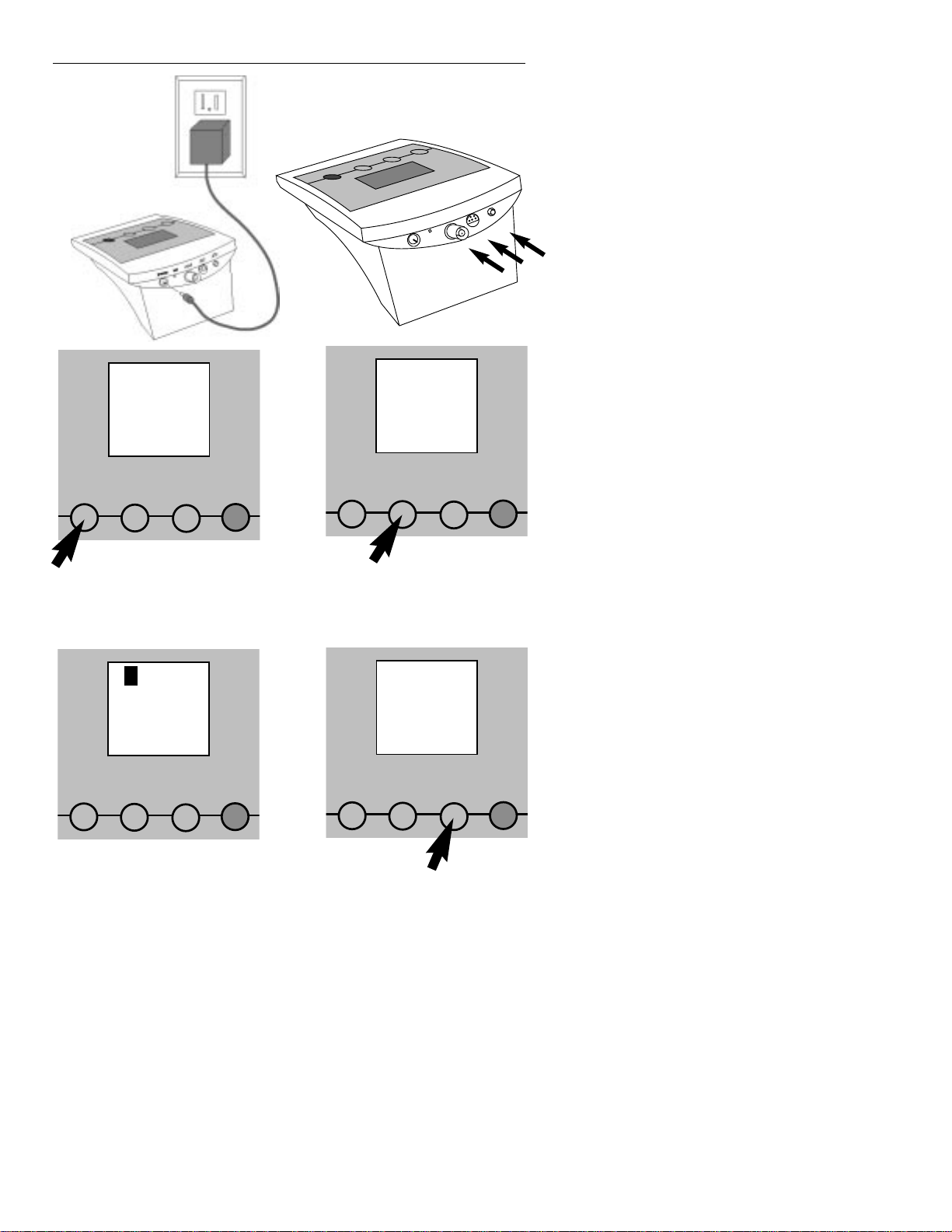
1. Connect power
cable to meter
power jack and
to AC power
source.
power
ref
input
FET
ATC
2. Connect the glass electrode to the
input and ATC connectors, or connect the FET electrode to the FET connector.
rel mV pH
3. Press pH/mV until the display indicates the appropriate measurement
mode.
4. Standardize the meter using
up to three buffers by immersing the electrode in a buffer,
then pressing Standardize to
enter each buffer.
Standardizing
PHB900 Series pH Meter Quick Reference
5. The display shows the current
reading in pH,mV,or relative
mV units.
6. Press Setup to review electrode calibration and to clear
or select buffer sets.
%slope
Clear
Set Buffers
Measuring
S
ii
pH/mV Standardize
pH/mV Standardize
Setup Enter
Setup Enter
pH/mV Standardize
pH/mV Standardize
Setup Enter
Setup Enter
Page 5
Getting Started
1
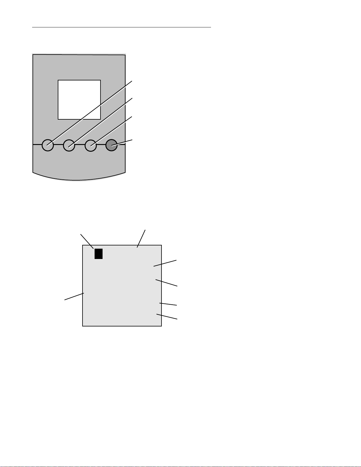
pH/mV Standardize
Setup Enter
pH/mV - button toggles
between pH and mV modes.
Standardize - the meter recognizes and displays buffers.
Setup - use to clear buffers
and to select new set of
buffers.
Enter - use to enter buffers.
Digital Display
100.0°C
%slope rel mV pH
-18.0.0.0
Good Electrode Error FET
Standardizing Clear
Measuring Set Buffers
2 4 7 10 12 1 3 5 8 10 13
1.68 4.01 6.86 9.18 12.46
1.08 3.06 4.86 6.79 9.23 12.76
S
Stability
Icon
Temperature
Mode
Front Panel Controls
Result
Electrode
Check
Icons
Prompts
Buffer
Icons
Page 6
power
ref
input
FET
ATC
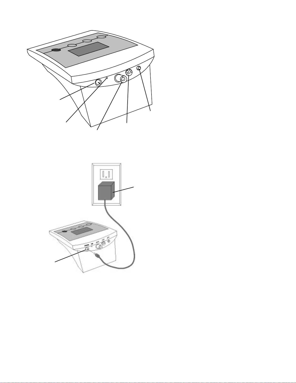
Rear Panel Connectors
Power
Cable
Connector
Reference
Electrode
Connector
Glass pH or
ISE
Electrode
Connector
FET
Electrode
Connector
Temperature
Probe
2
AC
Adapter
Power
Connector
Page 7
Installing and Maintaining Electrodes
This meter allows you to use two types of pH electrodes: the
pH glass electrode and the field effect transistor (FET) pH electrode.If both types of electrodes are installed,the meter will
read the FET electrode.
NOTE: If both electrodes are connected to the meter, do not put them in a solution together
because you will get inaccurate measurements.
3
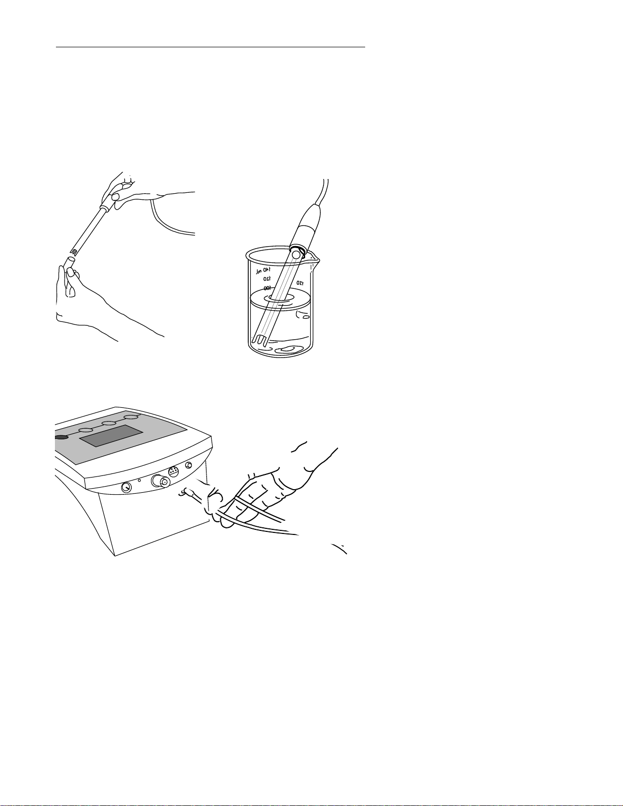
1.Remove the protective end
cover from electrode.
3.Remove the shorting cap on the BNC connector.Install the combination glass pH electrode by plugging it into the input connection (twist-lock) and the ATC connector into the ATC jack.
2.Before first use of your glass pH
electrode,or whenever the
electrode is dry,soak over-night
in a filling or KCI solution.
ATC
FET
input
ref
er
w
o
p
Page 8

4
ATC
4.
Option:
Install the optional FET electrode by plugging it into the FET
jack on the back of the meter panel.Allow the FET electrode to
warm up for one minute prior to use.
5.
Option:
Install ORP or Ion Selective Electrode pairs by removing the
BNC shorting cap and plugging the BNC connector (twist-lock)
into the BNC jack.If a combination electrode is not used, plug the
reference electrode into the ref pin.
FET
input
ref
er
w
o
p
ATC
FET
input
ref
er
w
o
p
Page 9

5
6. Rinse and blot-dry electrodes between each
measurement (do not
wipe).Rinse electrodes
with distilled water or
deionized water,or part
of the next solution to be
measured.
7. Store glass and FET pH electrodes in electrode filling solution or KCI solution.Always
leave the filling hole open
and refill with filling solution
when the internal solution
level gets low.
Page 10

6
E
Standardizing for pH Measurement
Because electrodes vary in their response,you must standardize your pH meter and electrode to compensate for electrode
variation.The more frequently you standardize,the more
accurate your measurements.Standardize daily,or more
often,for accurate results.
1.Immer se electrode in a buffer
solution.Stir gently.
pH
4.12
2.Press and release the pH/mV
button until your digital display indicates pH mode.This
button toggles between pH
and mV modes.
pH
Clear
Buffers
3.Clear existing buffers when
doing a new 2 or 3 point standardization.Use the Setup
button to clear existing buffers
and to select a new set of
buffers.
4.Press Standardize.The meter
recognizes the buffer and
flashes a buffer icon.When
the signal is stable,or when
you press Enter,the buffer is
entered.
pH
4.00
Standardizing
4
nter
pH/mV Standardize
Setup Enter
pH/mV Standardize
Setup Enter
pH/mV Standardize
Setup Enter
Page 11

7
pH/mV Standardize
5.The meter displays the %slope
of the electrode as 100.0% On
entering a second or third
buffer,the meter performs a
diagnostic check on the electrode.
%slope
100.0
4
6.To enter a second buffer,
place the electrode in the
second buffer solution and
press Standardize again.The
meter recognizes the buffer
and displays the first and second buffer icons.
pH
7.00
Standardizing
4 7
7.Next, the meter performs a
diagnostic test of the electrode.The display indicates
either Good Electrode or
Electrode Error.The meter displays the % slope of the electrode.
8.Electrode Error indicates that
your electrode is not working
properly. The electrode
response must be between 90
and 105% slope.Measurements causing Electrode Error
are not accepted,used or
stored by the meter.
%slope
99.4
Good Electrode
4
%slope
82.3
Electrode Error
4
Setup Enter
pH/mV Standardize
Setup Enter
pH/mV Standardize
Setup Enter
pH/mV Standardize
Setup Enter
Page 12

8
pH/mV Standardize
9.To set a third standard,place
the electrode in the third
buffer solution and press
Standardize.The results will be
the same as in steps 6 and 7,
except the display will show
three buffer icons.
10.After enter ing each buffer,
the
Standardizing
icon goes
off and the
Measuring
icon
appears on the display to
indicate that the meter
returns to
Measuring
.
22.5°C
pH
10.03
Standardizing
4 7 10
11.The first set of buffers in the
meter is used at 25°C in
North America and, typically,
at 20°C in Europe.In pH
mode,press Standardize and
Setup together to show the
current buffer temperature
setting.Press both
Standardize and Setup again
to toggle between the temperature settings.Press Enter
to select the displayed temperature setting and to
return to
Measuring.
12.Standardize your meter and
electrode using at least two
buffers with pH values bracketing the expected pH of
your samples.Stirr ing with a
magnetic stir bar and stirrer
provides faster electrode
response.
25°C
Set Buffer
2 4 7 10 12
pH
10.00
Standardizing
4 7 10
NOTE: The meter continually
adjusts for temperature. Therefore,
buffers may vary slightly from the
nominal values because of temperature variations.
Setup Enter
pH/mV Standardize
Setup Enter
pH/mV Standardize
Setup Enter
Denver Instrument
22.2¡C
pH
S
6
0
.
4
g
n
i
r
u
s
a
e
M
4
Enter
Setup
Standardize
pH/mV
BASIC
Page 13

9
Using Setup
The Setup button lets you clear all the buffers that you have
entered,review calibration information,or select the buffer set
that you want.
NOTE: You can escape setup mode at any
time by pressing pH/mV.
1.Press Setup and the meter displays a flashing
Clear Buffers
icon.
Use this step only when
you wish to clear all buffers
you have entered
.To clear all
existing buffers, press Enter.The
meter clears all buffers and
returns to
Measuring.
2.Press Setup again to show
electrode performance.If the
meter has accepted an electrode and buffers, it will display
Good Electrode
,display
the slope between the first
and second buffers and display the two buffer icons.
3.Pressing Setup again shows
the electrode slope between
the second and third buffers
(if three buffers have been
entered) and shows the second and third buffer icons.
4.Press Setup again to display a
flashing
Set Buffers
icon and
to display the first buffer set
icons.
%slope
99.4
Good Electrode
4
pH
Set Buffers
2 4 7 10 12
pH
Clear
Buffers
%slope
98.7
Good Electrode
7 10
pH/mV Standardize
Setup Enter
pH/mV Standardize
Setup Enter
pH/mV Standardize
Setup Enter
pH/mV Standardize
Setup Enter
Page 14

10
5.Press Enter to select the set of
buffers shown on the display
or
Press Setup again to view the
next set of buffers. Continue
pressing Setup to view the
third and fourth buffer sets.
6.Press Enter to select the displayed buffer set that contains the buffer you want to
use.Press Setup again,or
press pH/mV at any time,to
return to
Measuring
.
NOTE: You may mix buffers
from different sets.
pH
Set Buffers
1.68 4.01 6.86 9.18 12.46
pH
Set Buffers
1 3 5 8 10 13
pH/mV Standardize
Setup Enter
pH/mV Standardize
Setup Enter
Page 15

11
E
Standardizing for Millivolt
Measurement (Relative Millivolts)
You will use millivolt measurement for measuring ion concentration
and for measuring redox potential (also called ORP, oxidation reduction potential).You will normally use an ion selective electrode (ISE),
combined with a reference electrode,to measure ion concentration.
The ISE senses the ion concentration and responds with a millivolt
potential.The millivolt readings are then used to calculate ion concentrations.You will normally use a platinum indicator electrode,
combined with a reference electrode,to measure redox potential
(ORP).ORP measurements indicate the oxidizing or reducing capability of a solution.You can use ORP values to monitor or control solutions requiring a set amount of oxidants or reductants.
1.Immer se electrode in a standard solution.
mV
100.0
2.Press the pH/mV button until
your digital display indicates
mV mode.
3.Press Standardize to enter a
mV standard and read relative mV.
NOTE: Relative mV mode is not
allowed with the FET electrode.
4.When the signal becomes stable,or when you press Enter,
the current absolute mV
value becomes zero relative
millivolts.
rel mV
0.0
Measuring
mV
100.0
Standardizing
nter
pH/mV Standardize
Setup Enter
pH/mV Standardize
Setup Enter
pH/mV Standardize
Setup Enter
Page 16

pH/mV Standardize
5.To clear a mV offset and
return to absolute millivolt
mode,press Setup.The meter
displays a flashing
Clear
icon,
and the current relative millivolt offset.
6.To clear your previous mV
standard,press Enter.You then
return to absolute mV mode.
rel mV
0.0
Measuring
mV
100.0
Clear
12
Measuring pH or Millivolts
1.Standardize your meter. See page 10.
2.Rinse electrode and immerse in sample solution.Stir gently.
3.Press pH/mV until your display indicates the correct mode.
4.The display shows the current reading in pH, mV,or relative
mV units.When the signal is stable, the meter displays the S
icon.The S icon means the signal is changing less than 0.007
pH or 0.08 mV from the prior reading.
5.You may receive an out of range error, Err,if your electrode is
not immersed in a solution.To correct the error,immerse the
electrode in a solution.
6.Separate calibrations for the glass and FET electrodes are
stored in memory.Plugging the FET in recalls it’s calibration,
unplugging the FET recalls the glass electrode calibration.
Measuring
S
rel mV pH
Err
Electrode Error
Measuring
Setup Enter
pH/mV Standardize
Setup Enter
pH/mV Standardize
Setup Enter
pH/mV Standardize
Setup Enter
Page 17

13
Understanding pH Theory
Defining pH
The measurement of pH plays an important role in identifying
and controlling acidity and alkalinity levels for industry and
research. pH is a measure of the acidity or alkalinity of a solution and can be represented by this equation:
pH = -log [H+]
with [H+] representing the concentration of hydrogen ions in
the solution. pH is sometimes referred to as the power of the
hydrogen ion in a solution.
By using a pH meter,you can determine exact pH levels of
solutions. For example, rather than say that lemon juice is quite
acidic,you can say that lemon juice has a pH of 2.4. An
exact pH value can be used to control or measure acidity levels for manufacturing processes or for basic research.
pH values generally range from 0 to 14,with a pH value of 7
being the neutral point,or the value of pure water. The pH
values above the neutral point represent increasing alkalinity,
whereas pH values below the neutral point represent increasing acidity (Figure 1).
Strong Acid
Lemon Juice
Tomato Juice
Coffee
Pure water
Baking Soda
Ammonia
Strong Base
Neutral
0 1 2 3 4 5 6 7 8 9 10 11 12 13 14
more acidic
more basic
pH
Figure 1.
pH Scale showing the relative acidity or basicity
of some common substances.
Page 18

Measuring pH
To measure pH with a conventional glass pH electrode,the
meter uses a pH-sensing glass bulb electrode that is sensitive
to hydrogen ions.The potential developed at the glass bulb is
directly related to the pH of the solution.
The glass bulb electrode is paired with a reference electrode
which completes the electrical measuring circuit and provides
a stable reference point.These two electrodes are joined to
create a combination electrode.The combination glass electrode is connected to the pH meter which reads the voltage,
converts it to pH units,and displays the result.
Combination Glass pH Electrode
This meter can also use a field effect transistor (FET) electrode
for measuring pH.The FET uses an ion-sensitive solid state
membrane attached to the transistor to measure the hydrogen ion concentration of a solution.The FET is paired with a
reference electrode and counter electrode that maintain a
constant potential while the FET responds to the sample.
14
Reference
Electrode
(Outer Body)
Glass
Membrane
Glass
Electrode
(Inner Body)
Porous
Junction
Glass
Membrane
Temperature
Sensor
Reference
Electrode
pH-Sensitive
Membrane
Counter
Electrode
FET
Temperature
Sensor
Annular Porous
Junction
Page 19

Troubleshooting
15
Err
Electrode Error
1. If the signal from the electrode is
out of range
,the display will show Err.This may
happen when the electrode
is not in a solution.
Electrode Error
2. The meter will display
Electrode Error
when it
detects an error in electrode
response.During standardization,the message indicates
that the electrode is less than
90% or more than 105% of the
correct response.The
Electrode Error
message can
indicate either a bad electrode or bad buffer(s).
Err°C
Error
3. If the meter detects an error
in the temperature probe,the
display shows
Err°C
.If you do
not use a temperature probe,
the meter uses the default
temperature that you set to
either 20°C or 25°C.
4. To test the pH electrode,
place it in a good pH 7
buffer. Press pH/mV to use the
mV mode,and note the millivolt reading.Repeat for either
a pH 4 or pH 10 buffer. The
electrode signal must be
within the limits shown below
(when temperature is near
25°C).
Electrode Test
pH 7 0 + 30 mV
pH 4 159 to 186 mV
more than pH 7
pH10 159 to 186 mV
less than pH 7
pH/mV Standardize
Setup Enter
pH/mV Standardize
Setup Enter
pH/mV Standardize
Setup Enter
Page 20

16
Cal
Error
5. To test the meter for correct operation,install the BNC (input) shorting cap.
Press pH/mV to use the mV mode,and note the mV reading.If the meter
reads ) + 0.5 mV,it is measur ing correctly.
6. If the meter detects a loss of
calibration or a hardware
error during its power-up selftest,the display shows
CAL
Error
.This means the mV
accuracy may be reduced,
but pH accuracy after standardization will be the same.
Press Enter to continue using
the meter.If recalibration is
desired,contact Technical
Support.
ATC
FET
input
ref
er
w
o
p
pH/mV Standardize
Setup Enter
Page 21

Meter Specifications
pH -1.99 to 19.99 pH
displayed to 0.01 pH
accurate to 0.01 pH
mV -1800.0 to 0.01 mV
displayed to 0.1 mV
accurate to 0.5 mV
Temperature -5.0 to 105.0°C
displayed to 0.1°C
accurate to 0.1·°C
Standardization 0,1, 2 or 3 buffers
Auto buffer recognition 22 buffers
2,4, 7, 10,12
1,3, 6,, 8,10, 13
1.68,4.0, 6.86, 9.18,12.46
1.09,3.06, 4.65, 6.79,9.23, 12.75
Auto Temperature Compensation
Automatic electrode slope correvtion for 90-105%
Direct reading with both a glass and FET pH electrode
17
Page 22

Page 23

WARRANTY/DISCLAIMER
MEGA ENGINEERING, INC. warrants this unit to be free of defects in materials and
orkmanship for a period of 37 months from date of purchase. OMEGA Warranty adds an
dditional one (1) month grace period to the normal three (3) years product warranty to
over handling and shipping time. This ensures that OMEGA’s customers receive maximum
overage on each product.
the unit should malfunction, it must be returned to the factory for evaluation. OMEGA’s
ustomer Service Department will issue an Authorized Return (AR) number immediately upon
hone or written request. Upon examination by OMEGA, if the unit is found to be defective it will
e repaired or replaced at no charge. OMEGA’s WARRANTY does not apply to defects resulting
om any action of the purchaser, including but not limited to mishandling, improper interfacing,
peration outside of design limits, improper repair, or unauthorized modification. This
WARRANTY is VOID if the unit shows evidence of having been tampered with or shows evidence
f being damaged as a result of excessive corrosion; or current, heat, moisture or vibration;
mproper specification; misapplication; misuse or other operating conditions outside of OMEGA’s
ontrol. Components which wear are not warranted, including but not limited to
ontact points, fuses, and triacs.
MEGA is pleased to offer suggestions on the use of its various products. However,
MEGA neither assumes responsibility for any omissions or errors nor assumes liability for
ny damages that result from the use of its products in accordance with information proided by OMEGA, either verbal or written. OMEGA warrants only that the parts
manufactured by it will be as specified and free of defects. OMEGA MAKES NO OTHER
WARRANTIES OR REPRESENTATIONS OF ANY KIND WHATSOEVER, EXPRESSED OR
MPLIED, EXCEPT THAT OF TITLE, AND ALL IMPLIED W ARRANTIES INCLUDING ANY WAR-
ANTY OF MERCHANTABILITY AND FITNESS FOR A P AR TICULAR PURPOSE ARE HEREBY
ISCLAIMED. LIMITATION OF LIABILITY: The remedies of purchaser set forth herein are
xclusive and the total liability of OMEGA with respect to this order, whether based on con-
act, warranty, negligence, indemnification, strict liability or otherwise, shall not exceed
he purchase price of the component upon which liability is based. In no event shall OMEGA
e liable for consequential, incidental or special damages.
ONDITIONS: Equipment sold by OMEGA is not intended to be used, nor shall it be used: (1) as
“Basic Component” under 10 CFR 21 (NRC), used in or with any nuclear installation or activity;
r (2) in medical applications or used on humans. Should any Product(s) be used in or with any
uclear installation or activity, medical application, used on humans, or misused in any way,
MEGA assumes no responsibility as set forth in our basic WARRANTY/DISCLAIMER language,
nd additionally, purchaser will indemnify OMEGA and hold OMEGA harmless from any liability
r damage whatsoever arising out of the use of the Product(s) in such a manner .
RETURN REQUESTS / INQUIRIES
irect all warranty and repair requests/inquiries to the OMEGA Customer Service Department.
EFORE RETURNING ANY PRODUCT(S) TO OMEGA, PURCHASER MUST OBTAIN AN
UTHORIZED RETURN (AR) NUMBER FROM OMEGA’S CUSTOMER SERVICE DEPARTMENT
N ORDER TO AVOID PROCESSING DELAYS). The assigned AR number should then be
marked on the outside of the return package and on any correspondence.
he purchaser is responsible for shipping charges, freight, insurance and proper packaging to
revent breakage in transit.
OR W
ARRANTY RETURNS, please have
he following information available BEFORE
ontacting OMEGA:
. P.O. number under which the product was
PURCHASED,
. Model and serial number of the product
under warranty, and
. Repair instructions and/or specific
problems relative to the product.
FOR NON-WARRANTY REPAIRS,
consult
OMEGA for current repair charges. Have the
following information available BEFORE
contacting OMEGA:
1. P.O. number to cover the COST
of the repair,
2. Model and serial number of product, and
3. Repair instructions and/or specific problems
relative to the product.
MEGA’s policy is to make running changes, not model changes, whenever an improvement is possible.
his affords our customers the latest in technology and engineering.
MEGA is a registered trademark of OMEGA ENGINEERING, INC.
Copyright 1996 OMEGA ENGINEERING, INC. All rights reserved. This document may not be copied, photocopied,
produced, translated, or reduced to any electronic medium or machine-readable form, in whole or in part, without
ior written consent of OMEGA ENGINEERING, INC.
UUSASA
MADE
ININ
Page 24

M2832/0298
Where Do I Find Everything I Need for
Process Measurement and Control?
OMEGA…Of Course!
TEMPERATURE
MU
Thermocouple, RTD & Thermistor Probes, Connectors, Panels & Assemblies
MU
Wire: Thermocouple, RTD & Thermistor
MU
Calibrators & Ice Point References
MU
Recorders, Controllers & Process Monitors
MU
Infrared Pyrometers
PRESSURE, STRAIN AND FORCE
MU
Transducers & Strain Gauges
MU
Load Cells & Pressure Gauges
MU
Displacement Transducers
MU
Instrumentation & Accessories
FLOW/LEVEL
MU
Rotameters, Gas Mass Flowmeters & Flow Computers
MU
Air Velocity Indicators
MU
Turbine/Paddlewheel Systems
MU
Totalizers & Batch Controllers
pH/CONDUCTIVITY
MU
pH Electrodes, Testers & Accessories
MU
Benchtop/Laboratory Meters
MU
Controllers, Calibrators, Simulators & Pumps
MU
Industrial pH & Conductivity Equipment
DATA ACQUISITION
MU
Data Acquisition & Engineering Software
MU
Communications-Based Acquisition Systems
MU
Plug-in Cards for Apple, IBM & Compatibles
MU
Datalogging Systems
MU
Recorders, Printers & Plotters
HEATERS
MU
Heating Cable
MU
Cartridge & Strip Heaters
MU
Immersion & Band Heaters
MU
Flexible Heaters
MU
Laboratory Heaters
ENVIRONMENTAL
MONITORING AND CONTROL
MU
Metering & Control Instrumentation
MU
Refractometers
MU
Pumps & Tubing
MU
Air, Soil & Water Monitors
MU
Industrial Water & Wastewater Treatment
MU
pH, Conductivity & Dissolved Oxygen Instruments
 Loading...