

Page 1
http://www.omega.com
e-mail: info@omega.com
User ’s Guide
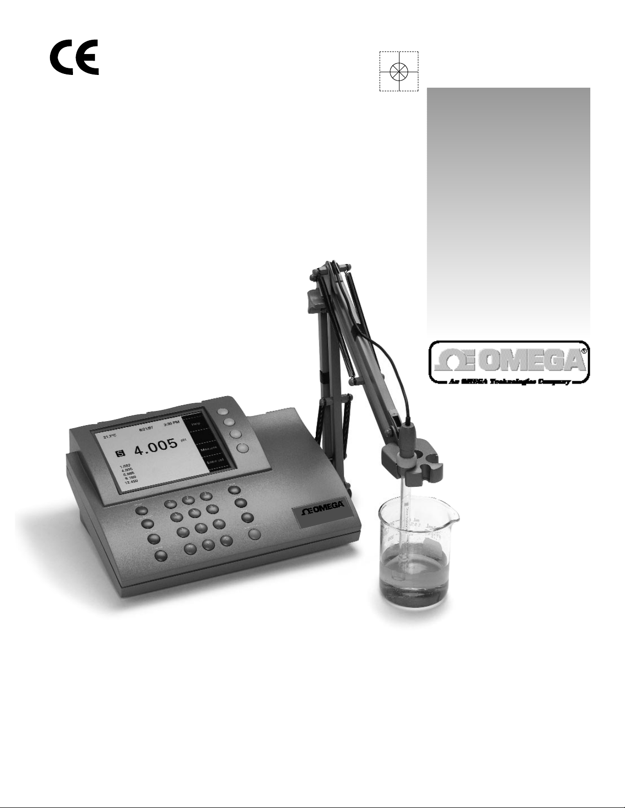
PHB-215 pH Meter
PHB-220 pH/Conductivity Meter
PHB-225 pH/Ion Meter
PHB-250 pH/Ion/Conductivity Meter
PHB-215
pH m
eter
Page 2

Servicing North America:
USA: One Omega Drive, Box 4047
ISO 9001 Certified Stamford, CT 06907-0047
Tel: (203) 359-1660 FAX: (203) 359-7700
e-mail: info@omega.com
Canada: 976 Bergar
Laval (Quebec) H7L 5A1
Tel: (514) 856-6928 FAX: (514) 856-6886
e-mail: canada@omega.com
For immediate technical or application assistance:
USA and Canada: Sales Service: 1-800-826-6342 / 1-800-TC-OMEGA
SM
Customer Service: 1-800-622-2378 / 1-800-622-BEST
SM
Engineering Service: 1-800-872-9436 / 1-800-USA-WHEN
SM
TELEX: 996404 EASYLINK: 62968934 CABLE: OMEGA
Mexico and
Latin America:
Tel: (95) 800-TC-OMEGA
SM
FAX: (95) 203-359-7807
En Espan÷ol: (203) 359-7803 e-mail: espanol@omega.com
Servicing Europe:
Benelux: Postbus 8034, 1180 LA Amstelveen, The Netherlands
Tel: (31) 20 6418405 FAX: (31) 20 6434643
Toll Free in Benelux: 06 0993344
e-mail: nl@omega.com
Czech Republic: ul. Rude armady 1868, 733 01 Kavrine-Hranice,
Czech Republic
Tel: 420 (69) 6311627 FAX: 420 (69) 6311114
e-mail: czech@omega.com
France: 9, rue Denis Papin, 78190 Trappes
Tel: (33) 130-621-400 FAX: (33) 130-699-120
Toll Free in France: 0800-4-06342
e-mail: france@omega.com
Germany/Austria: Daimlerstrasse 26, D-75392 Deckenpfronn, Germany
Tel: 49 (07056) 3017 FAX: 49 (07056) 8540
Toll Free in Germany: 0130 11 21 66
e-mail: germany@omega.com
United Kingdom: 25 Swannington Road, P.O. Box 7, Omega Drive,
ISO 9002 Certified Broughton Astley, Leicestershire, Irlam, Manchester,
LE9 6TU, England M44 5EX, England
Tel: 44 (1455) 285520 Tel: 44 (161) 777-6611
FAX: 44 (1455) 283912 FAX: 44 (161) 777-6622
Toll Free in England: 0800-488-488
e-mail: uk@omega.com
omega.comomega.com
OMEGAnetSMOn-Line Service Internet e-mail
http://www.omega.com info@omega.com
It is the policy of OMEGA to comply with all worldwide safety and EMC/EMI regulations that
apply. OMEGA is constantly pursuing certification of its products to the European New Approach
Directives. OMEGA will add the CE mark to every appropriate device upon certification.
The information contained in this document is believed to be correct but OMEGA Engineering, Inc. accepts
no liability for any errors it contains, and reserves the right to alter specifications without notice.
WARNING: These products are not designed for use in, and should not be used for, patient connected applications.
OMEGA
TM
®
Page 3

Quick Start Guide for pH Measurement . . . . . . . . . . . . . . . . . . . . . . . . . . . Page ii
Introduction
Menu Keys,Softkeys and Display . . . . . . . . . . . . . . . . . . . . . . . . . . . . . . . . . . . 1
Electrode Connectors and Inputs . . . . . . . . . . . . . . . . . . . . . . . . . . . . . . . . . . 2
LCD Display . . . . . . . . . . . . . . . . . . . . . . . . . . . . . . . . . . . . . . . . . . . . . . . . . . . 3
Function Keys . . . . . . . . . . . . . . . . . . . . . . . . . . . . . . . . . . . . . . . . . . . . . . . . . . 4
Electrodes
Preparing pH and Ion Selective Electrodes. . . . . . . . . . . . . . . . . . . . . . . . . . . 6
Connecting Electrodes. . . . . . . . . . . . . . . . . . . . . . . . . . . . . . . . . . . . . . . . . . . 6
Using and Storing Electrodes . . . . . . . . . . . . . . . . . . . . . . . . . . . . . . . . . . . . . . 7
pH Electrodes . . . . . . . . . . . . . . . . . . . . . . . . . . . . . . . . . . . . . . . . . . . . . . . . 7
Solid-State FET Electrodes. . . . . . . . . . . . . . . . . . . . . . . . . . . . . . . . . . . . . . . 7
Ion Selective Electrodes . . . . . . . . . . . . . . . . . . . . . . . . . . . . . . . . . . . . . . . . 7
Meter Setup
Meter Setup Menu . . . . . . . . . . . . . . . . . . . . . . . . . . . . . . . . . . . . . . . . . . . . . . 8
pH Mode
pH Mode Standardization Menu . . . . . . . . . . . . . . . . . . . . . . . . . . . . . . . . . . . 9
Cal Reminder Menu . . . . . . . . . . . . . . . . . . . . . . . . . . . . . . . . . . . . . . . . . . . . . 9
Select Custom Buffer Set. . . . . . . . . . . . . . . . . . . . . . . . . . . . . . . . . . . . . . . . . . 9
pH Mode Options Menu. . . . . . . . . . . . . . . . . . . . . . . . . . . . . . . . . . . . . . . . . 10
Standardizing and Measuring pH. . . . . . . . . . . . . . . . . . . . . . . . . . . . . . . . . . 12
Clearing Buffers. . . . . . . . . . . . . . . . . . . . . . . . . . . . . . . . . . . . . . . . . . . . . . . . 12
mV Mode
mV Mode Standardization Menu. . . . . . . . . . . . . . . . . . . . . . . . . . . . . . . . . . 13
mV Mode Options Menu . . . . . . . . . . . . . . . . . . . . . . . . . . . . . . . . . . . . . . . . 13
Clearing Relative mV Mode. . . . . . . . . . . . . . . . . . . . . . . . . . . . . . . . . . . . . . 13
Quick Start Guide for Ion Measurement. . . . . . . . . . . . . . . . . . . . . . . . . . . . . . . 14
Ion Mode
Ion Mode Standardization Menu. . . . . . . . . . . . . . . . . . . . . . . . . . . . . . . . . . 15
Standardizing and Measuring Ion . . . . . . . . . . . . . . . . . . . . . . . . . . . . . . . . . 16
Measuring Ion using a Known Addition type (incremental ion) method. . . 17
Quick Start Guide for Conductivity/Resistivity/Salinity/TDS Measurement. . . . 18
Conductivity/Resistivity/Salinity/TDS Modes
Conductivity/Resistivity/Salinity/TDS Standardize Menu . . . . . . . . . . . . . . . . 19
Conductivity/Resistivity/Salinity/TDS Options Menu . . . . . . . . . . . . . . . . . . . . 20
Data logging . . . . . . . . . . . . . . . . . . . . . . . . . . . . . . . . . . . . . . . . . . . . . . . . . . . . 21
Troubleshooting . . . . . . . . . . . . . . . . . . . . . . . . . . . . . . . . . . . . . . . . . . . . . . . . . . 22
Meter Specifications . . . . . . . . . . . . . . . . . . . . . . . . . . . . . . . . . . . . . . . . . . . . . . 23
pH Theory . . . . . . . . . . . . . . . . . . . . . . . . . . . . . . . . . . . . . . . . . . . . . . . . . . . . . . . 24
Ion Selective Electrode Theory . . . . . . . . . . . . . . . . . . . . . . . . . . . . . . . . . . . . . . 24
Determining Isopotential Point . . . . . . . . . . . . . . . . . . . . . . . . . . . . . . . . . . . . . . 25
RS-232 Serial Interface Meter Command Set. . . . . . . . . . . . . . . . . . . . . . . . . . . 26
Maintenance . . . . . . . . . . . . . . . . . . . . . . . . . . . . . . . . . . . . . . . . . . . . . . . . . . . . 28
Table of Contents
i
Page 4
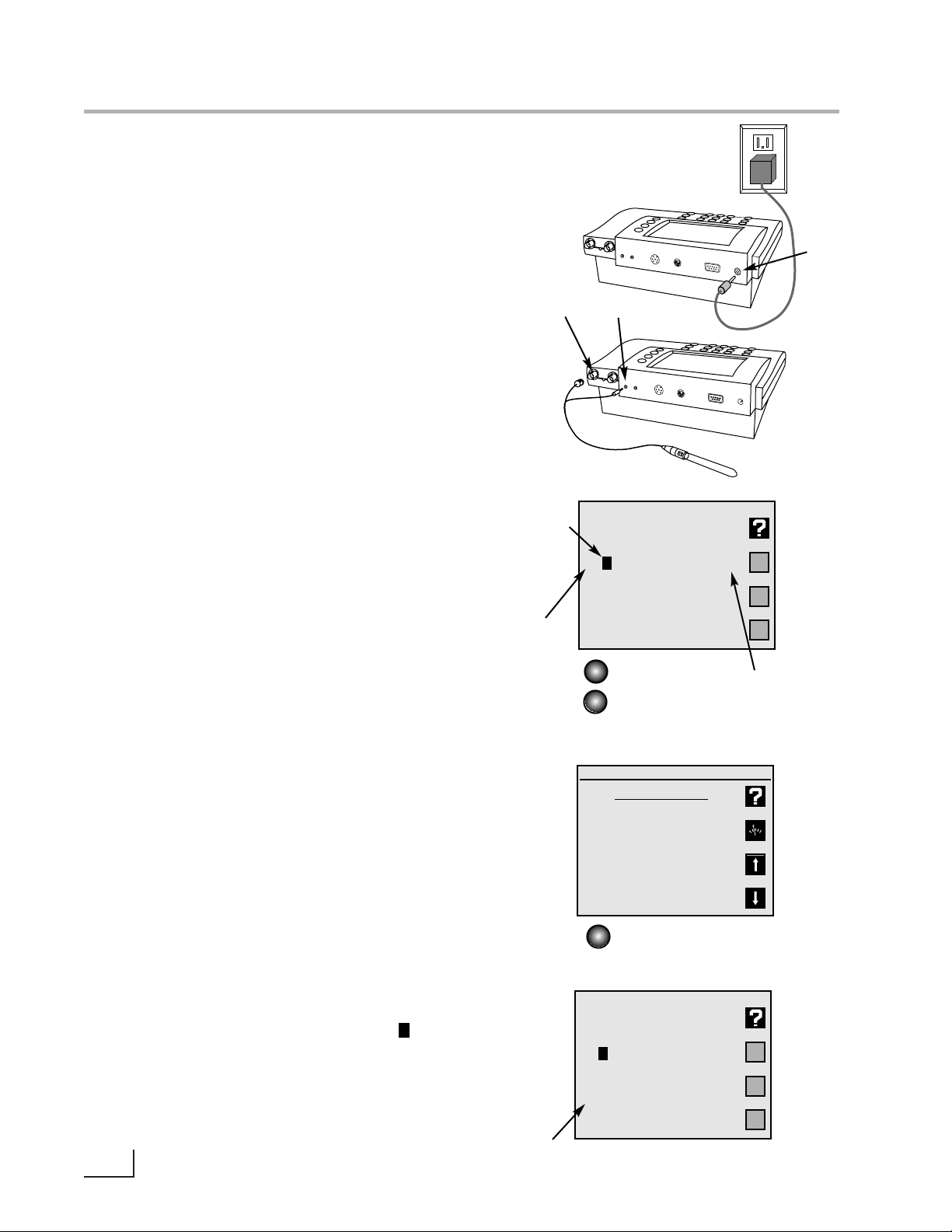
1.Connect power cable to meter connector on
the rear panel marked “power”and to AC power
source.
2.Connect the glass pH/ATC electrode to the
channel A BNC connector marked “ch.A”and to
the channel A temperature connector marked
“temp A”.
3.Verify the meter is in pH mode on channel A.Use
the Mode key and Channel key to set the meter
to the correct mode and channel if necessary.
(See Function keys).
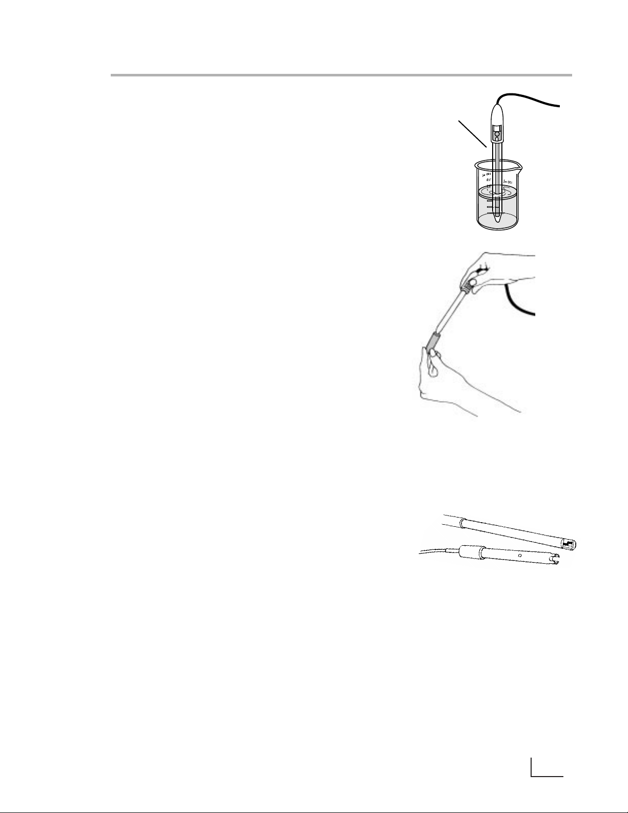
4.Standardize the electrode by immersing the
electrode in a buffer,pressing Standardize, pressing 1) Auto-enter a buffer and following the
prompts.Repeat this step to enter each buffer.
The meter will check the electrode and buffers,
and give an error message if there is a problem.
Press Standardize to enter or clear buffers,select
buffers, set resolution, or set other parameters for
the current mode and channel.
5.The display shows the current measurement,and
indicates a stable reading with the indicator.
Press Cal Data to review and graph the electrode calibration data.
ii
Quick Start Guide for pH Measurement
A 7.000
pH
25.0°C
No buffers.
Mode
Channel A: pH mode
Standardize Menu
1) Auto-enter a buffer
2) Manual buffer entry
3) Clear buffers
4) Options menu
5) Cal reminder menu
6) Select buffer set
channel
indicator
units
indicator
Channel
Standardize
A 7.000
pH
25.0°C
4.008 pH
7.000
entered
buffers
“power”
“ch. A”
“temp A”
s
s
stability
indicator
s
c
h
. A
re
f. A
c
h
T
e
m
c
p
o
. A
n
d
. C
T
e
m
p
. B
R
S
2
3
2
C
p
o
w
e
r
c
h
. A
c
h
re
f. A
T
c
e
o
m
n
p
d
. A
. C
T
e
m
p
. B
R
S
2
3
2
C
p
o
w
e
r
Page 5
This Omega meter is a powerful,versatile and accurate instrument. It features
easy menu-based operation with easy to understand prompts and
electrode/standard error checking.
These meters feature many advanced options,such as programmable stability
criteria, programmable standardization reading delay times, multi-channel operation,fast reading update rates of twice per second for all channels,programmable alarms, programmable data logging of 500 data points and a superb RS232 serial interface for controlling the meter and obtaining data.
Omega meters use flash programmable ROM for the operating code.The meter
operating code can easily be upgraded as new features are made available.
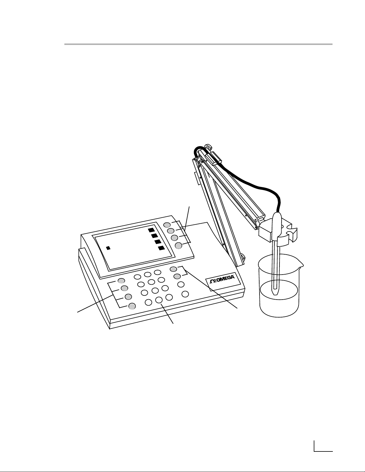
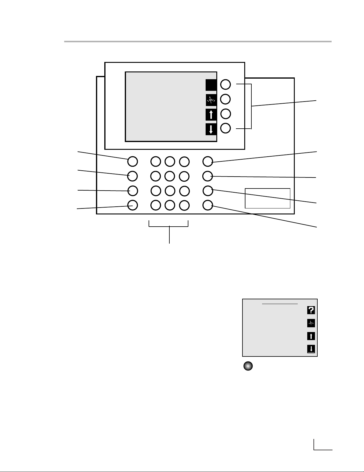
Direct Menu Keys, Softkeys and Display
The meter uses six Direct Menu keys to access the menus and operations (such
as selecting pH mode,standardizing,checking electrode calibration data,
selecting the electrode channel).
There are four Softkeys that provide additional operations; these Softkeys
change their function as needed and each Softkey has an icon to indicate its
current function.
The display is a backlit quarter-VGA screen capable of displaying all four electrode channels (of a PHB-250) simultaneously. The backlight will turn off after a 45
minute period of non-use; pressing any key will automatically turn the backlight
on again.
A S
7.001
pH
25.0¡C
4.008 pH
7.000
6/30/1998 02:28 PM
Denver Instrument
S
1
Introduction
Softkeys
Direct Menu
Keys
Direct Menu
Keys
Numeric
Keypad
PHB-215
pH m
eter
Page 6
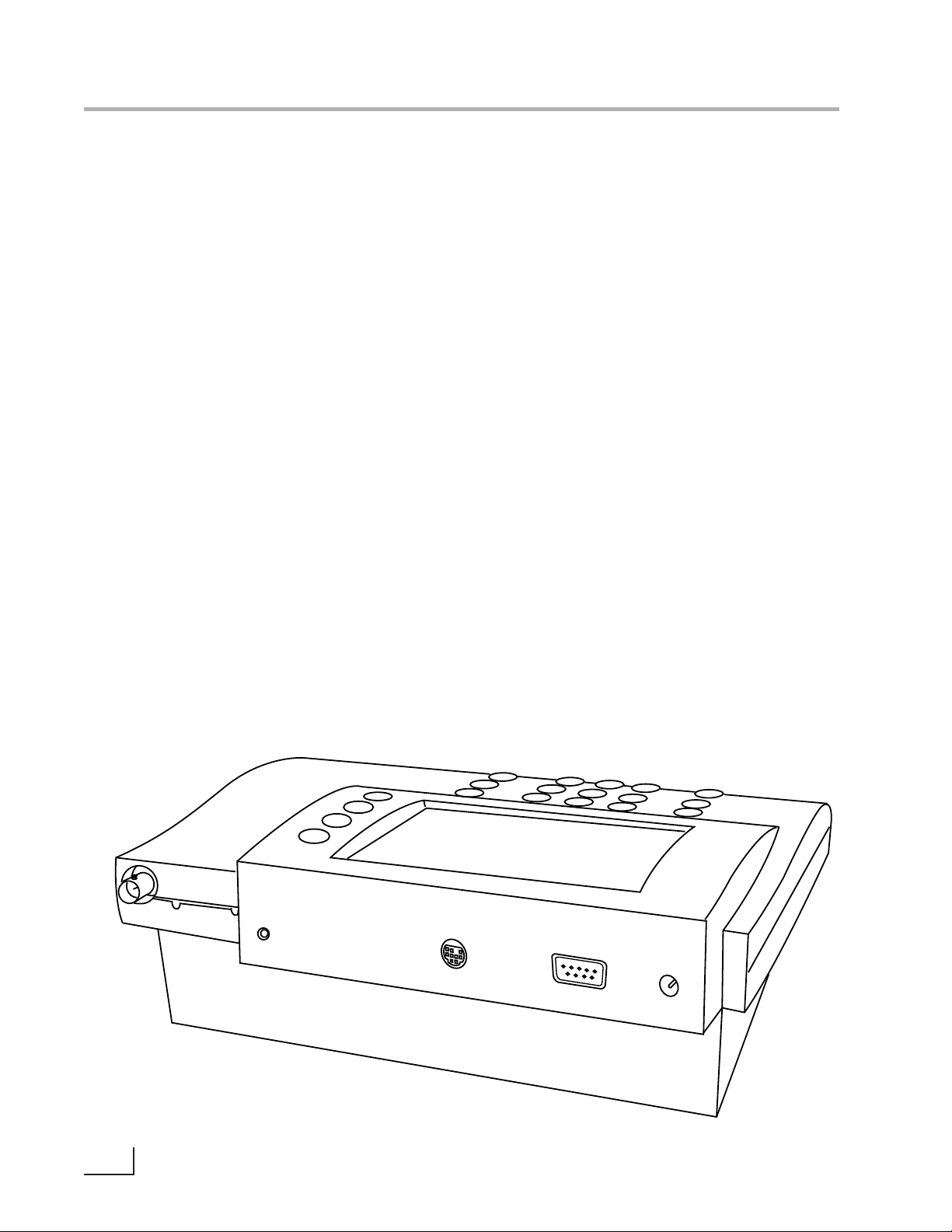
Electrode Connectors and Inputs
BNC ("ch.A" or "ch.B") connectors: pH,Ion
Selective Electrodes and ORP (redox) electrodes attach to the meter through a BNC
("round twist-on") connector to channel A or
channel B (PHB-225 and PHB-250 only).
Temperature ("temp A" or "temp B") connectors: use to connect the 2.5mm mini-phone
plug from the temperature sensor (built into
the pH electrode with the Omega standard
pH/ATC electrode) for Automatic Temperature
Compensation (ATC).
Reference ("ref.A" or "ref.B") connectors: use
for attaching a reference electrode tip-pin
plug when a separate reference electrode is
used.
Conductivity DIN (“ch.C conductivity”)
connector: use to connect a 4-band conduc-
tivity/ATC cell.These 4-band cells offer
improved linearity and stability over older 2band conductivity cells. (PHB-220 and PHB-250
only).
FET DIN ("ch.F FET") connector: use to connect
the Denver Solid-State Field Effect Transistor
(FET) pH/ATC electrode. These non-glass pH
electrodes offer certain advantages over conventional glass pH electrodes.
Serial port ("RS232") DB-9 connector: use to
connect a serial printer or Personal Computer.
This bi-directional interface outputs data and
receives meter commands.
Power (“power”) connector: use to connect a
5.5mm OD x 2.1 ID coaxial connector with
12VDC at 500mA (center pin negative).
2
Introduction
Connectors for PHB-250
ch. A
ref. A
ref
temp
A
ch. F
FET
RS232C
power
Page 7
D
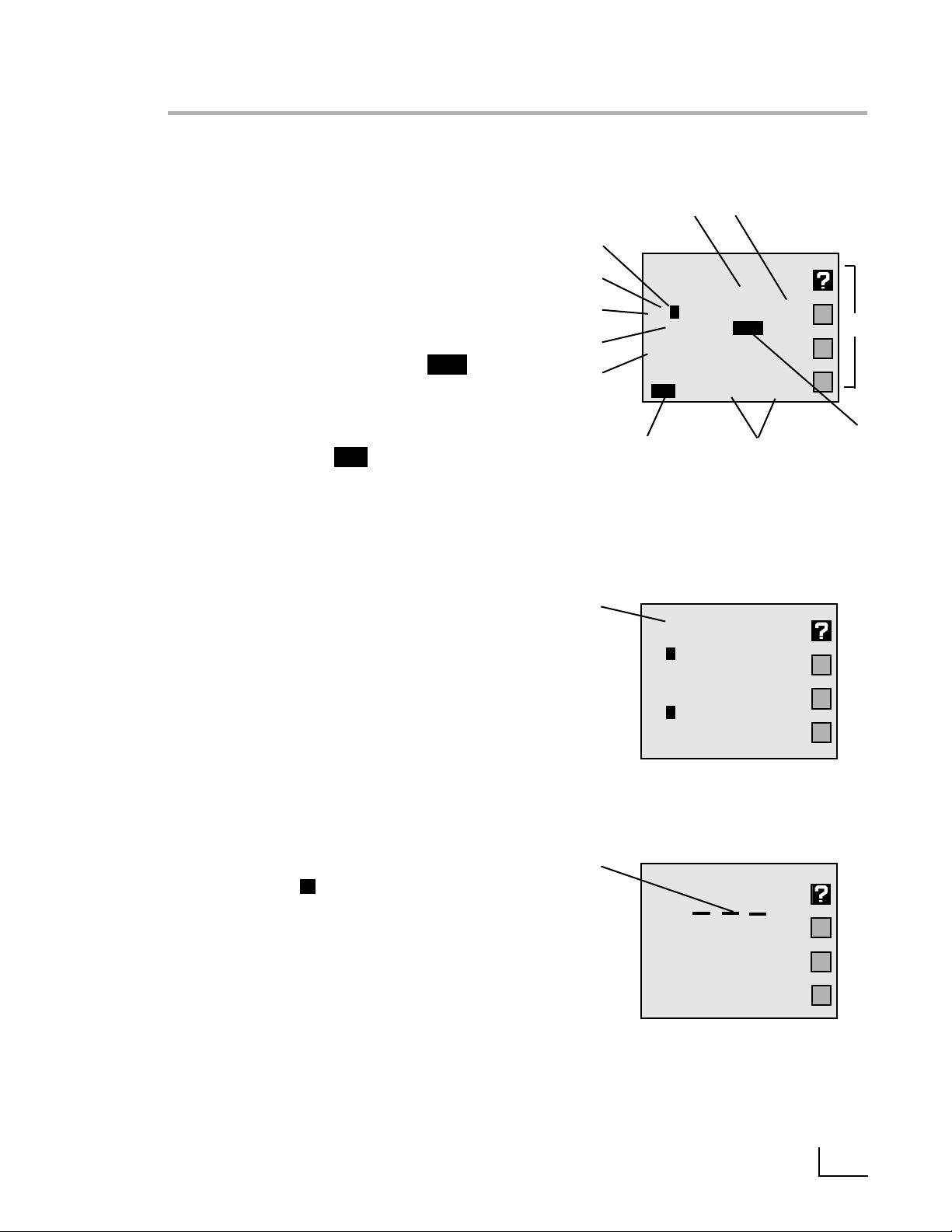
Note: Not all of the following will display at the
same time.
A
. Result: current measurement.
B
.Units: displays the units for the current measure-
ment.Examples: pH, mV, mg/L F-,µS/cm or
W-cm.
C
.Softkey icons: show the current function
assigned to each softkey.
D
.Calibration due reminder: the icon means
a calibration is now due.
E
. Date and time: displayable in different formats.
F
.Da talogging: the icon indicates datalog-
ging is active.
G
.Buffers/Standards: in single channel mode,all
entered buffers or standards are displayed.A
“!”symbol beside a buffer indicates that buffer
is out of the entered calibration valid time (See
Calibration reminder,page 9).
H
.Temperature: displays the measured tempera-
ture when an electrode with ATC or separate
temperature probe is attached.Shows “M”
when a manually entered temperature is being
used.
I
.Alar m: “*”indicator means data is outside the
set alarm limits.
J
Channel: indicates which electrode channel
(input) is being displayed.Channel A and
Channel B (PHB-225 only) are BNC inputs.
Channel F is the FET electrode input.
K
.Stability: the indicates the electrode is sta-
ble to the selected criteria.
L
.Multiple Channel: display can show two
(PHB- 215),three (PHB-220 and PHB-225) or four
(PHB-250) electrode measurements with temperature simultaneously.
M
.Out-of-range or non-valid reading: dashes indi-
cate a measurement is not available.This usually means the reading is out of range,or can
mean in ion mode that no standards have
been entered,or strict calibration has been set
and the calibration expired.
3
Display
*
A 7.000
pH
25.0°C
4.008 pH
7.000
9.999
6/30/1998 02:28 PM
A B
J
I
H
G
E
C
Single channel display
K
F
A 6.998
pH
24.6°C
B 1.02
mg/L
23.4°C F-
30-6-1998 14:28:05
Dual channel display
L
A pH
23.8
°
C
1998.6.30 14:28:30
M
s
s
s
CAL!
Log
S
Page 8
A
.Mode: Selects the mode: pH,mV
(PHB-215),Ion (PHB-225 and PHB-250),
Conductivity - Resistivity-NaCl SalinityPractical Salinity-TDS (PHB-220 and
PHB-250) to use for the currently selected
channel (electrode input).
B
.Standardize: Enters buffers or standards
for the currently selected channel and
mode.Use to enter pH buffers,relative mV
offset,ion standards or conductivity /resistivity standards.
Also used to change other settings which
affect the measurement.
C
.Cal Data: Displays and graphs buffers or
standards with time and date stamp and
electrode calibration data for the selected channel and mode.
D
.Channel: Selects the channel(s) (elec-
trode inputs) to display.The PHB-215 can
display one or two channels simultaneously (Channels A and F).The PHB-225
can display one,two or three channels
simultaneously (Channels A,B and F). The
PHB-220 can display up to three channels
(Channels A,C and F).The PHB-250 can
display up to four channels (Channels A,
B,C and F).
E
.Setup: The Setup menu is used to set vari-
ous general meter settings,such as date
and time,display contrast,keypress beep
and serial port.
F
.Da ta Log: Displays the datalogging menu
used to set datalogging and view the
stored Data Log (see Datalogging).
G
.Clear: Exits from the current menu and
returns to the previous menu,cancels the
current operation or clears a number
entry.
H
.Enter/Pr int: Accepts numeric values,menu
selections or pending operations.In the
main measure screen,acts as a Print key,
sending all current measurements to a
printer/ computer through the serial port
and stores the measurements in the Data
Log.
I
.Softkeys: These four keys access different
operations at different times.Most menus
offer a “Help” softkey and the “Measure”
softkey, w hich allows a direct return to the
main measuring screen,exiting all menus
immediately. The “Up Arrow”and “Down
Arrow”softkeys offer one way to select a
menu item.The “Left Arrow”key is a backspace,active during number entry.
J
.Numer ic Keys: Pressing a number key
selects a numbered item in a menu.The
number keys also allow entering values for
buffers, standards, and various meter settings.
4
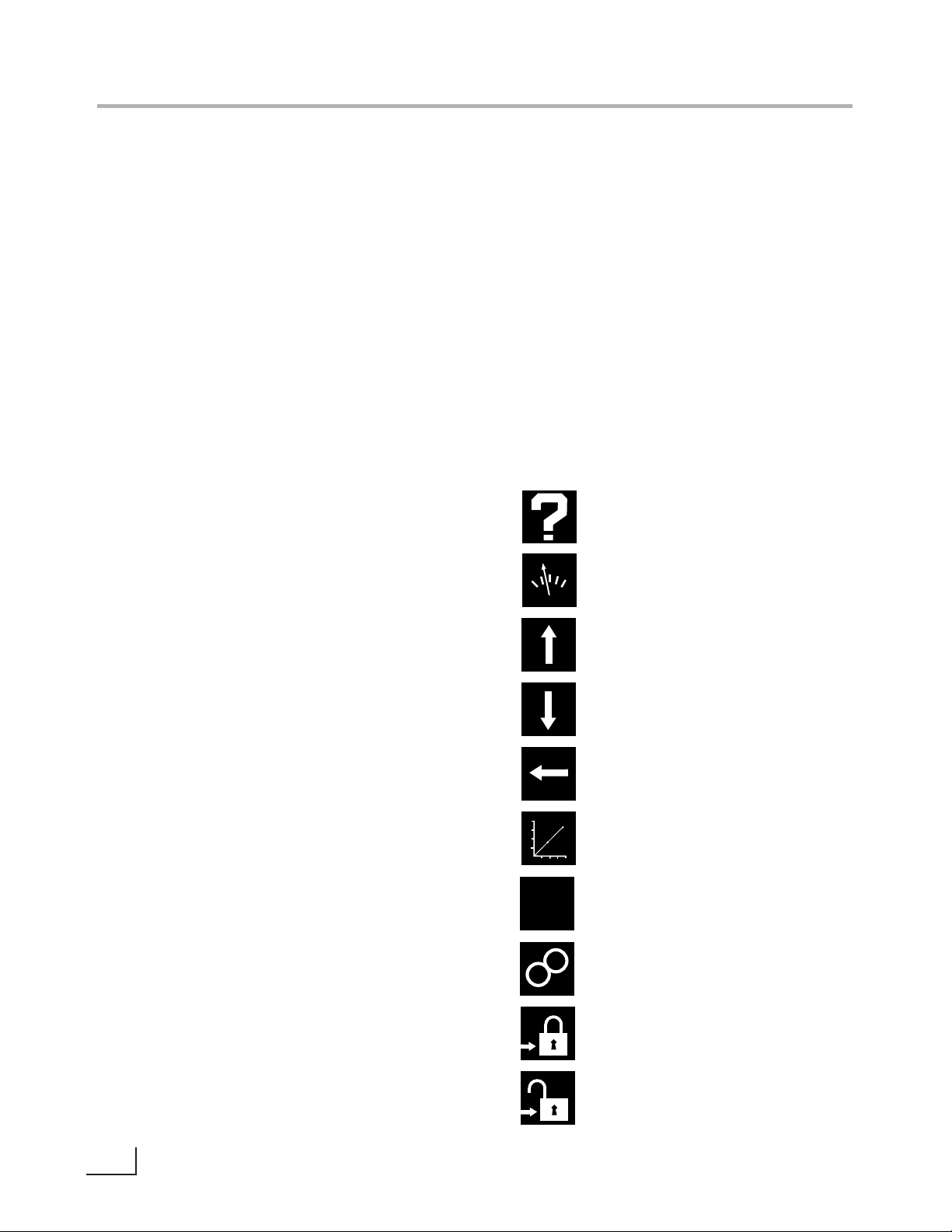
Function Keys
Help
Measure
Scroll up
Scroll down
Backspace
Graph
Exponent number entry
Incremental ion method
Measure lock
Measure unlock
Softkeys
E
–
+
Page 9
5
Function Keys
A
B
C
D
E
F
G
H
I
J
Channels
The Channel key is used to turn on or off each
available channel.In single-channel operation,
additional information for the selected channel is
provided,including a display list of all entered
buffers or standards. In multi-channel operation,
the Mode,Standardize and Cal Data menus ask
for the channel before accessing the menu.
The PHB-215 offers single or dual channel operation using channel A ( pH and ORP electrodes)
and channel F (Solid-state FET pH electrode).The
PHB-225 offers up to three-channel simultaneous
operation of channel A and channel B (pH,ORP
and Ion Selective Electrodes) and channel F
(Solid-state FET pH electrode).
The PHB-220 has Channel A (pH and ORP electrodes),Channel C (Conductivity cells) and
Channel F (solid-state FET pH electrode).The
PHB-250 provides up to four channel measurement with Channel A and Channel B (pH and
ORP and Ion Selective electrodes),Channel C
(Conductivity cells) and Channel F (solid-state
FET pH electrode).
Configure Display
1) Turn channel A on/off: ON
2) Turn channel B on/off: ON
3) Turn channel F on/off: OFF
4) Turn channel C on/off: ON
5) Measurement screen
PHB-250 Select Channel
screen
Channel
?
Mode
Standardize
Data Log
Cal Data
Channel
Enter/Print
Setup
Clear
Page 10
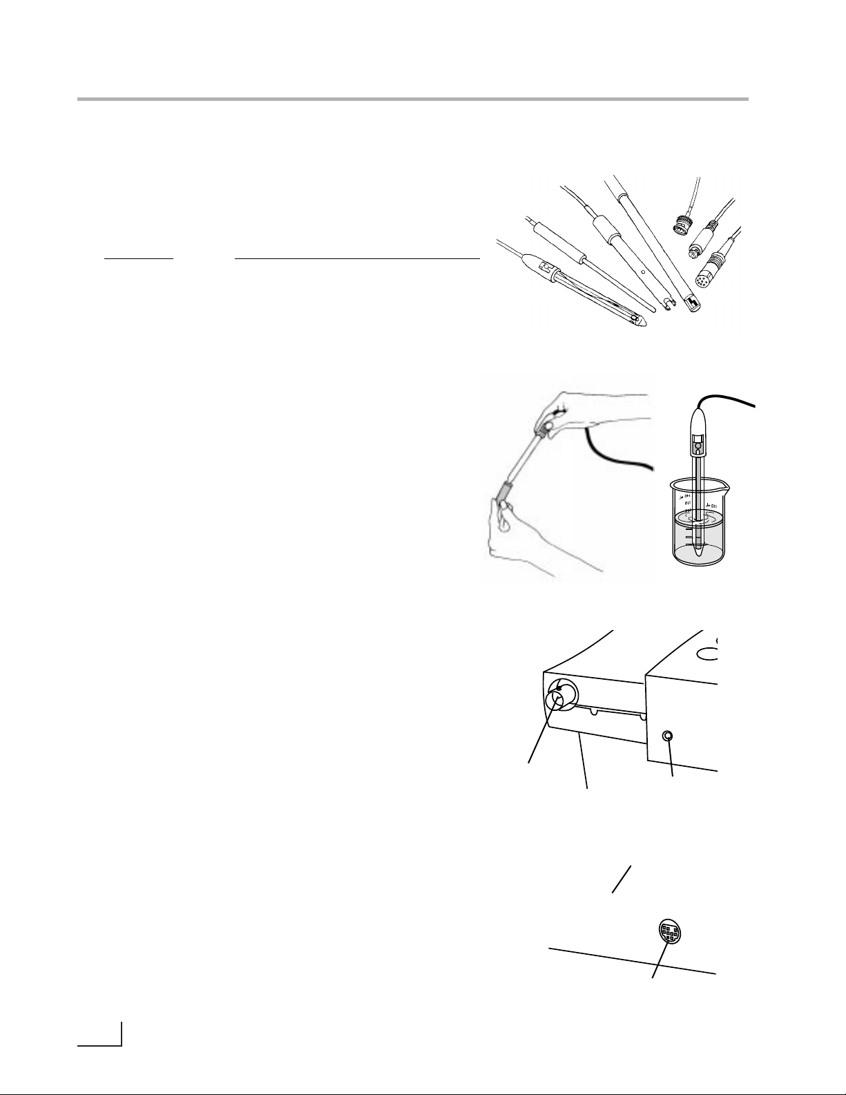
The meter allows you to use a variety of glass membrane (“glass”) pH/ATC electrodes,ion selective electrodes,Conductivity/ATC cells,the Omega Field Effect
Transistor (FET) Solid-State pH/ATC electrode,temperature (ATC) probes, combination electrodes using a BNC
connector,or separate electrode pairs with BNC connector and reference pin.
Preparing Electrodes and Conductivity Cells
Remove the wetting cap or storage cap from the electrode.Before first using your pH electrode or whenever
the electrode is dry,soak it several hours in an electrode filling or storage solution (3 Molar KCl solution) or
in a buffer for pH electrodes. Condition ISE’s in the recommended solutions. Rinse Conductivity cells with
deionized water before use.
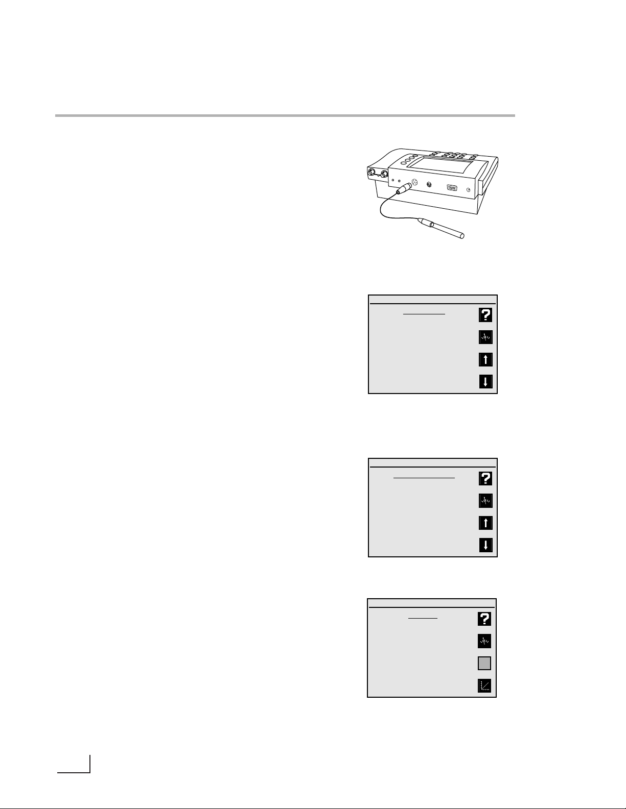
Connecting Electrodes
pH, ORP or ISE electrodes (with BNC connector):
Connect the electrode to the BNC input,either channel A or channel B (PHB-225 and PHB-250 only),located
at the rear of the meter.Push in and rotate the electrode’s BNC connector until it locks in place.Connect
the ATC connector to the temp.A or temp.B connector. To disconnect, twist the BNC connector in the
opposite direction and pull.
Electrode Pair Using a Reference Electrode (with
Reference Pin Plug):
Connect the indicating electrode to the BNC input.
Connect the reference electrode to the Reference
input.Push the electrode’s tip pin plug into the input to
connect and pull out to disconnect.
Conductivity Cells (with DIN connector):
Align and push in the DIN connector fully to the channel C input (PHB-220 and PHB-250 only).Pull carefully to
disconnect.
6
Electrodes
To measure Use channel (connector)
pH A (BNC)*
or
B (BNC)*
mV (ORP) A (BNC)*
or
B (BNC)*
ion (ISE) A (BNC)*
or
B (BNC)*
Conductivity C (DIN)
Resistivity C (DIN)
Salinity C (DIN)
TDS C (DIN)
pH (FET) F (mini-DIN)
*Separate reference electrodes can be used with “Ref A”or
“Ref B”connectors
BNC
Connector
Channel C
Conductivity Input
ATC
Connector
Channel F
FET pH Input
ch. A
ref. A
ref
temp
A
ch. F
FET
Page 11
Using and Storing Electrodes
pH Electrodes
• Provide moderate stirring for faster electrode
response.
• Leave the fill hole open during all use.
• Rinse the electrode between each measurement
with a portion of the next sample or buffer to be
measured,or with deionized or distilled water.
• Keep glass electrodes wet when not being used
by placing some electrode filling solution in the
wetting cap and storing with the wetting cap on.
• Keeping glass electrodes “wet”will improve their
performance.Store electrodes in electrode filling
solution or storage solution (3M KCl).
Solid-State FET Electrode
• All models allow use of both standard glass
pH/ATC and Solid-State FET (Field Effect Transistor)
pH/ATC electrodes.The meter can store a calibration for both types of electrodes.Plug the FET
electrode into the channel F mini-DIN input.
• Allow the FET about 1 minute to stabilize when
first connected.The FET electrode can be stored
dry or in electrode storage solution.Provide moderate stirring.
Ion Selective Electrodes
• Add proper amount of Ionic Strength Adjuster
(ISA) to all standards and samples,usually 1 mL
ISA to 50 mL standard or sample.
• Provide moderate stirring for faster electrode
response.
• Rinse the electrode(s) between each measurement with a portion of the next sample or standard to be measured,or with deionized or distilled water.
• Follow the instruction sheets for the individual
electrode.Store as recommended.
Conductivity Cells
• When changing samples or standards,immerse
the cell into the new solution,then lift and allow
solution to drain out.Repeat two more times.
• Gently tap cell to dislodge air bubbles.
7
Electrodes
Store with wetting
cap and Fill
Solution (3M KCl)
Provide
moderate
stirring
Store FET and
Conductivity
Cells dry
Page 12

Meter Setup Menu
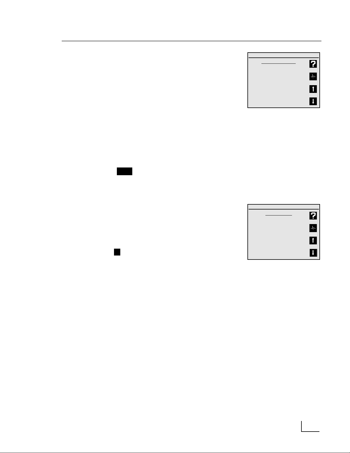
Press Setup to access the Meter Setup menu:
1.Time and date menu: use to set the time format
(HH:MM AM/PM or HH:MM:SS),set the time,set the
date format (MM/DD/YY,DD-MM-YY or YYYY.MM.DD),
and set the date.
2.Select temperature units: use to select temperature
measurement and display in degrees Celsius,degrees
Fahrenheit or Kelvin.
3.Select contrast: use to select the display contrast, making the displayed characters lighter or darker.Select
setting “5”for typical conditions.
4.Select baud rate: use to set the ser ial RS232 port baud
rate. This must match the baud rate setting of the
printer or computer being used with the meter.
5.Setup serial port: use to configure the serial port start
bits and parity setting. This must match the settings of
the printer or computer being used with the meter.
6.Keypress beep on/off: use to turn on or off a "beep"
upon each keypress as an audible signal that a key
has been pressed.
7.Select video color scheme: use to set the display to
black characters on a white background or white
characters on a black background.
8.Show meter information: use to show the meter
model,software version and serial number.
9.Enable measure lock: use to enable the measure lock
where a stable measurement is locked (frozen) for
later review. Sta bility criter ia should be set to SLOW for
all channels and modes in use.
0.Enable strict calibration: use to set strict calibration
where no measurements are displayed if the calibration reminder has expired.
“±”Set screen saver timeout: use to set a time for the
backlight to turn off and the screensaver to activate.
"•" Restore factory defaults: use to reset all settings to
factory defaults.On occasion it may be useful to
completely reset the meter,for example,if other users
have changed a setting.
Warning!
A reset also clears all electrode standardizations.
8
Meter Setup
!
Meter Setup Menu
1) Time and date menu
2) Select temperature units
3) Select contrast
4) Select baud rate
5) Setup serial port
6) Keypress beep on/off
7) Select video color scheme
8) Show meter information
9) Enable measure lock
0) Enable strict calibration
±) Set screen saver timeout
•) Restore factory defaults
Setup
Select Time Format
1) hr : min : sec
2) hr : min AM/PM
Select Date Format
1) mm / dd / yyyy
2) dd – mm – yyyy
3) yyyy.mm.dd
Enable Measure Lock
Display lock/unlock softkey?
1) Yes
2) No
If “measure lock” is enabled, a
“lock” soft key will appear on
the measurement screen
Enable Strict Calibration
Require calibration?
1) Yes
2) No
If strict calibration is enabled,
no measurements will be
displayed for a channel with an
expired cal reminder.
Page 13

9
pH Mode
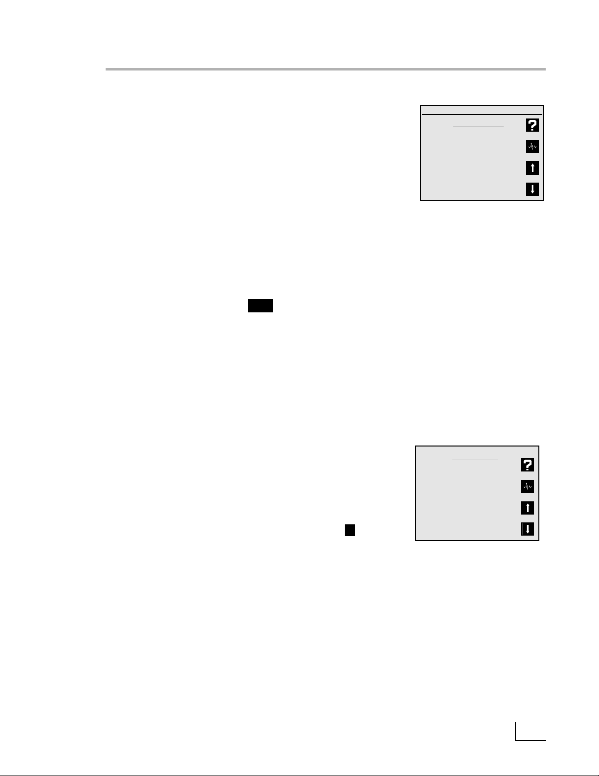
pH Mode Standardize Menu
Press Mode and select 1) pH.
Press Standardize and the pH Mode Standardize
Menu appears:
1.Auto-enter a buffer: use to add a new buffer which
is auto recognized by the meter,or update an existing buffer.Follow the prompts.
2.Manual buffer entry: use to enter a buffer value by
manually entering the pH of the buffer.
3.Clear buffers: use to clear all buffers entered for the
current channel (pH mode).If all entered buffers are
being re-entered,it is usually not necessary to clear
buffers before re-entering them.
4.Options Menu: A menu of additional specific pH
mode settings. (See page 10).
5.Cal reminder menu: use to set a timer reminding
you to recalibrate.A icon will appear on the
main screen and an exclamation mark will appear
beside the buffers for which time has expired.
The calibration reminder is a reminder of when
electrode calibration (with buffers) should be
redone.It is based on elapsed time from the oldest
entered buffer.
If strict calibration is set (see Meter Setup Menu),when
a calibration has expired the icon appears, and
"- - - " is displayed in place of the measurement. No
measurements can be obtained until a calibration is
performed.
Note: When strict calibration is set,the calibration
reminders for all channels are turned ON,and can't
be turned off from the Cal Reminder Menu.
6.Select buffer set: There are five auto-recognition
buffer sets and the option to configure and use a
custom buffer set of your own.
Select custom buffer set
Use Custom Buffer Set to make a set of buffers containing the specific buffers in use (up to five buffers).
Select Custom Buffer Set,configure the custom
buffer set,then buffers from this set will be automatically recognized and entered.
Custom buffers can have any numeric pH value,or
can be selected from the built-in temperature corrected buffers. Using the built-in buffers allow temperature correction of the pH values of the buffers ,
offering more accuracy.
Channel A: pH mode
Standardize Menu
1) Auto-enter a buffer
2) Manual buffer entry
3) Clear Buffers
4) Options Menu
5) Cal reminder menu
6) Select buffer set
Standardize
Channel A: pH mode
Manual Buffer Entry
Enter the actual pH of this
buffer, after correcting
for temperature:
pH
Press Enter to accept.
Channel A: pH mode
Cal Reminder Menu
1) Turn reminder On/Off: OFF
2) Set reminder interval:
01, 00 : 00 days, hr : min
3) Standardization menu
When the cal reminder expires, a “CAL!”
(or “!”) icon will be displayed with the
measurement and with each expired standard. If strict cal is ON, reminders are
always ON, and expired channels show no
measurements.
Channel A: pH mode
Select Buffer Set
1) 2, 4, 7, 10, 12 at 25C
2) 2, 4, 7, 10, 12 at 20C
3) 1, 3, 6, 8, 10, 13
4) 1.68, 4.01, 6.86, 9.18, 12.46
5) 1.09, 3.06, 4.65, 9.23, 12.75
6) Select custom buffer set
Custom Buffer
No buffers
CAL!
Channel A: pH mode
Configure Custom Buffer Set
1) Add a “built-in” buffer
2) Add a manual buffer
3) Delete a buffer
4) Standardize menu
Custom Buffer Set
No buffers
CAL!
Page 14

pH Mode Options Menu
1.Select resolution: use to set pH readings to 0.1,0.01,
or 0.001 pH units.
2.Select stability criteria: use to set stability criteria to
slow,medium or fast to match the electrode's speed
of response and the variability of the signal allowed
for a “stable” ( ) measurement.
3.Select signal averaging: use to set filtering of the
electrode signal to very slow (10 readings),slow (8),
medium (6),fast (4) or very fast (2). Slower settings
give more stable readings,although may require
longer times to reach stability.
4.Set standardization delay: use to set a reading delay
time for the meter to wait before accepting an electrode signal during standardization.Programming a
standardization reading delay helps slow responding
electrodes reach equilibrium before the electrode
signal is accepted.
5.Set pH slope: use to set a known electrode slope
used by the meter with a zero- or single-point standardization.The normal default slope is 59.16 mV/pH.
The meter allows between 80 and 120 % efficiency to
be entered.
6.Standardize menu: Retur ns to the pH mode
Standardization Menu.
7.Manual temperature menu: use to set a temperature
to be used in the absence of an ATC probe or when
manually overriding the ATC.
8.Data alarm menu: use to set pH limits.If the limits are
exceeded an alarm indication (“*”) is displayed and
recorded with any data points placed in the Data
Log.
9.Set isopotential point: use to set an isopotential point
for use in high accuracy electrode measurements
(See Isopotential,page 20).
10
pH Mode
Channel A: pH mode
Options Menu
1) Select resolution
2) Select stability criteria
3) Select signal averaging
4) Set standardization delay
5) Set pH slope
6) Standardize menu
7) Manual temperature menu
8) Data alarm menu
9) Set isopotential point
S
Page 15

Notes:
1.Auto-recognized buffers are found in the Auto-recognized built-in buffer sets.These buffers are autorecognized by the meter,and are also automatically
temperature corrected for the variation of buffer pH
with temperature.
2.When manually entering buffers, the exact pH of the
buffer at the current temperature must be entered.
All buffers change pH with temperature.For best
accuracy, either use the built-in buffers or make sure
manually entered buffers are at the expected temperature (so that their pH as entered is correct).
3.Auto-recognition Buffer Sets:
1) 2,4, 7, 10, 12 (nominal value adjusted at 25°C)
2) 2,4, 7, 10, 12 (nominal value adjusted at 20°C)
3) 1,3, 6, 8, 10,13
4) 1.68,4.01, 6.86, 9.18, 12.46 (NIST buffers)
5) 1.09,3.06, 4.65, 9.23, 12.75 (DIN buffers)
6) Select custom buffer set
4.Temperature Correction of Electrodes and Buffers
The meter automatically compensates for the temperature dependence of the electrode's response when
measuring pH.The meter also compensates for buffer
change in pH value with temperature.Temperature
compensation is based on temperature either from an
ATC probe or a manually entered temperature.
Using a Solid-state FET (Field Effect Transistor)
pH/ATC Electrode
By turning channel F (FET) on,an Omega FET pH/ATC
electrode can be directly used.pH and mV modes are
available with the FET electrode.FET devices can have
large offset potentials that vary with each transistor
chip,so Manual buffer entry must be used to enter the
first buffer.After one buffer has been entered using
“Manual buffer entry”, following buffers can usually be
entered with “Auto-enter a buffer”.
pH Mode
Actual Buffer pH vs. Temperature
pH 4.00(4.01)/7.00/10.00 buffer (nominal 25°C)
Temperature Buffer 4 Buffer 7 Buffer 10
(°C)
30 4.016 6.991 9.947
25 4.008 7.003 10.000
20 4.003 7.020 10.057
15 4.000 7.042 10.119
10 3.998 7.069 10.187
11
Page 16

12
Standardizing and Measuring pH
1.Immerse the electrode in a buffer and stir moderately. The meter displays the current pH measurement.
2.Allow the electrode sufficient time to reach
equilibrium.
3.Press Standardize,then press either 1) Auto-enter a
buffer or 2) Manual buffer entry.
4.Follow the prompts on the display.
5.The meter waits for a stable signal,automatically recognizes the buffer (if using “Auto-enter”),checks the
electrode and buffer and enters the buffer.The
entered buffer appears in the display.
6.Alternatively,if the signal is not sta ble, you can press
Enter when the reading stabilizes according to your
tolerance criteria.The meter then enters the buffer.
7.Repeat steps 1 through 4 to enter a second,third,
fourth or fifth buffer.With more than one buffer the
meter performs a diagnostic check on the electrode.
The electrode is considered good if the slope is
between 90 to 105%.If a sixth buffer is entered,the
buffer farthest away is replaced by the new buffer.
Hints to achieve better accuracy:
• During standardization,allow time for the electrode
to stabilize before entering the buffer into the meter.
• Standardize using at least two buffers , bracketing the
expected pH of your samples.
• Standardize at least daily for the most accurate read-
ings.
• Open the Fill Hole on the electrode.
• Stir all buffers and samples.
• Rinse the electrode with DI water between samples
and buffers.
• Always use fresh buffers.
Clearing Buffers
Press Standardize,then press 3) Clear buffers to clear
buffers. If all previously entered buffers will be reentered,it is not necessary to clear buffers since the
meter will replace the previous values.If re-enter ing
only some buffers, all the old buffers should be cleared.
Channel A: pH mode
pH Checklist
Prepare buffer or sample.
Rinse electrode.
Place electrode in solution.
Stir moderately.
Press Enter to continue.
Channel A: pH mode
Standardize Menu
1) Auto-enter a buffer
2) Manual buffer entry
3) Clear buffers
4) Options menu
5) Cal reminder menu
6) Select buffer set
Standardize
Channel A: pH mode
Manual Buffer Entry
Enter the actual pH of this
buffer, after correcting
for temperature:
pH
Press Enter to accept.
mV
4 7 10
pH buffers
samples
Page 17

Electrode Potential,mV
Titrant Volume, mL
Redox Titration
Standardize
Millivolt measurements are used to measure ORP (oxidation-reduction potential) or redox potential,to
check performance of pH or Ion Selective Electrodes,
and for redox titrations.
The meter will measure millivolts (mV) by pressing Mode
and selecting 2) mV.Relative mV can be measured
by entering a mV offset or using the current mV value
as the mV offset.
mV Standardization Menu
In mV mode,press Standardize and the mV mode
Standardization Menu appears:
1.Auto-enter mV offset: use to set the relative mV offset equal to the current mV reading. The current mV
becomes 0.0 relative mV.
2.Set mV offset: use to manually enter a mV offset.
3.Clear mV offset: use to clear any offset that has
been entered,returning the meter to absolute mV
mode.
4.Options menu: a menu of additional settings specific to the mV mode.See below.
mV Mode Options Menu
1.Select resolution: use to set mV readings to 1 or 0.1
millivolt resolution.
2.Select stability criteria: use to select stability criteria
for slow, medium or fast response which use a tight,
average or loose requirement to indicate a “stable”
( ) reading.
3.Select signal averaging: use to set the meter to
average readings that are very slow (10 readings),
slow (8),medium (6),fast (4) or very fast (2).
4.Set standardization delay: use to set a length of time
for the meter to wait before entering a relative mV
standardization.
5.Set mV offset: use to manually enter a mV offset
(same as in the mV Standardize menu).
6.Standardization menu: retur ns to the mV
Standardization Menu.
Clearing Relative mV Mode
Press Standardize,then press 3) Clear mV offset to clear
offset and return the meter to absolute mV mode.
mV Mode
Channel A: mV mode
Standardize Menu
1) Auto-enter mV offset
2) Set mV offset
3) Clear mV offset
4) Options menu
Channel A: mV mode
Options Menu
1) Select resolution
2) Select stability criteria
3) Select signal averaging
4) Set standardization delay
5) Set mV offset
6) Standardize
13
S
Page 18

14
Quick Start Guide for Ion Measurements
1.Connect the Ion Selective Electrode (ISE) and
Reference Electrode,if required, to the
meter.”Combination” ISE’s have a reference
electrode built-in,and do not require a separate reference electrode or connection.
2.Prepare two or more ion standards at concentrations bracketing typical sample solutions.
Add the appropriate Ionic Strength Adjuster
solution to each standard.
3.Set the meter to display the correct channel
(the channel with the ISE attached,either A or
B) using Channel.Set the meter to Ion mode:
press Mode,then 3) Ion.
Note: The meter will display “— — —”(no valid
data) until an ion standard has been entered.
4.Place the electrode(s) in the standard,provide
stirring (a magnetic stirrer is recommended),
and allow sufficient time (1 to 5 minutes
depending on the ISE) for the electrode to
reach a stable signal.
5.Press Standardize,1) Enter a standard and follow the prompts.Repeat these steps to enter
up to seven ion standards.See the
Standardizing and Measuring Ion section for
more information.
6.Check the ISE response by pressing Cal Data to
see the standards and the ISE slope between
calibration points (standards).The meter will
allow an ion electrode slope between 5.92
mV/decade (10% slope) and 70.99
mV/decade (120% slope).
Mode
Channel
+
ISA
Example: 1 mg/L 10 mg/L Ionic Strength
Adjuster
BNC
ref
measuring or
Combination ISE
reference
Cal Data
Channel A:
Select Mode
1) pH
2) mV
3) Ion
Channel A: ion mode
Ion Cal Data
1.00 mg/l 08/01/1998 08:32 AM
57.15 mV/decade
10.0 mg/l 08/01/1998 08:35 AM
Channel A: ion mode
Standardize Menu
1) Enter a standard
2) Set ion slope
3) Clear standards
4) Options menu
5) Cal reminder menu
c
h
. A
re
f. A
c
h
T
e
m
p
. A
T
e
m
p
. B
R
S
2
3
2
C
p
o
w
e
r
E
Page 19
Ion Mode Standardization Menu
Select channel A or B.Press Mode and then press 3) Ion for ion
mode.Press Standardize and the Ion Mode Standardize Menu
appears.
1.Enter a standard: use to add a new standard or update (reenter) an existing standard.Follow the prompts.With the first
standard you select the ion name and units.
2.Set ion slope: use to manually enter a slope for the selected
ion electrode.Used with a one-point ion calibration.Useful if
the ISE has a known,stable slope,so that measurements can
be made after entering a single ion standard.
Note: when two or more standards are entered,the meter
uses the actual determined slope(s).
3.Clear standards: use to clear standards for the electrode
standardization selected.
4.Cal reminder menu: use to set a timer reminding you to
recalibrate.A icon will a ppear on the main screen
and an exclamation mark will appear beside the standards
which need to be re-entered.
5.Options Menu: use to set various additional parameters to
the ion mode.See below.
Ion Mode Options Menu
1.Resolution: use to set the readings to 1,2, or 3 significant digits.
2. Select stability criteria: use to set the sta bility cr iteria to slow,
medium or fast to match the electrode's speed and stability
of response,providing tight,medium and loose requirements
for a stable ( ) indication.
3.Select signal averaging: use to set filtering of the electrode
signal to very slow (10 readings),slow (8),medium (6),fast (4)
or very fast (2). Slower settings give more stable readings,
although may require longer times to reach stability.
4.Set standardization delay: use to set a reading delay time for
the meter to wait before accepting an electrode signal during standardization.Programming a standardization reading
delay helps slow responding electrodes reach equilibrium
before the electrode signal is accepted.Delays of one
minute for fast ISE’s and five to ten minutes for slow ISE’s are
appropriate.
5.Set ion slope: use to enter a known ion electrode slope for a
one point standardization.
6.Standardize menu: returns to the ion standardize menu.
7.Manual temperature menu: use to set a manual temperature
for use in the absence of an ATC probe or when manually
overriding the ATC.
8.Data alarm menu: use to enter ion limits to be entered. If the
limits are exceeded an alarm indication (“
*
”) is displayed.
9.Set isopotential point: use to enter an isopotential point. See
page 20.
0.Enable incremental: use to turn on the known addition/subtraction type ion methods.See page 17.
Ion Mode
Channel A: ion mode
Standardize Menu
1) Enter a standard
2) Set ion slope
3) Clear standards
4) Options menu
5) Cal reminder menu
Channel A: ion mode
Options Menu
1) Select resolution
2) Select stability criteria
3) Select signal averaging
4) Set standardization delay
5) Set ion slope
6) Standardize menu
7) Manual temperature menu
8) Data alarm menu
9) Set isopotential point
0) Enable incremental modes
15
CAL!
S
Page 20

16
Standardizing and Measuring Ion
Standardizing and Measuring Ion
1.Set the meter to ion mode (use Mode) and turn
ON the channel (use Channel) with the Ion
Selective Electrode (either Channel A or B).
The meter displays “— — —”,indicating no valid
measurement,until at least one ion standard has
been entered.
2.Prepare a standard,and add the appropriate
Ionic Strength Adjuster (ISA) solution to the standard.
3.Immerse the electrode(s) in the solution and stir
continuously.
4.Press Standardize,select the correct channel if
prompted to do so,and select 1) Enter a stan-
dard to add a standard. If this is the first standard
to be entered,select the ion name and units.
Follow the prompts.Be sure to allow enough time
for the electrode to reach a stable signal.
Note: The default standardization delay for ion
mode is 30 seconds.This can be set by the user.
See Ion Mode Options Menu,page 15.
5.The meter waits for a stable signal and enters the
standard.The entered standard appears in the
display (in single channel mode).Alternatively, if
the signal is not stable,you can press Enter when
the reading stabilizes according to your tolerance criteria.The meter then enters the standard.
6.Repeat steps 2 through 5 to enter additional
standards.Up to seven standards can be
entered.With more than one standard,the meter
performs a diagnostic check on the electrode.
Helpful Hints:
• Provide stirring.
• Allow the electrode time to reach a stable read-
ing before entering the standard into the meter.
• To achieve better accuracy, standardize using at
least two standards,bracketing the expected
range of your samples.
• Standardize from low to high concentrations.
• Always use fresh standards.
• Use standards and samples near the same tem-
perature.
• Remember to add Ionic Strength Adjuster to
each standard and sample.
mV
ion standards
log [ion]
Channel B: ion mode
A 25.0°C
No standards.
08/01/1998 08:40 PM
Channel B: ion mode
Ion Checklist
Prepare standard or sample.
Add Ionic strength Adjuster.
Rinse electrode.
Place electrode in solution.
Stir moderately.
Press Enter to continue.
Standardize
Channel A: ion mode
Standardize Menu
1) Enter a standard
2) Set ion slope
3) Clear standards
4) Options menu
5) Cal reminder menu
Page 21

Measuring Ion using Known Addition type
(Incremental Ion) Methods
The meter provides known ("standard") addition/subtraction and analate ("sample") addition/subtraction
incremental methods for measuring ion concentrations. These advanced ion measurement techniques
are useful in overcoming certain problems in ion
analysis.
In known addition/subtraction a volume of sample is
obtained,Ionic Strength Adjuster is added,and the
ion electrode potential is obtained. Then a small volume of standard is added to the sample,and a second electrode potential is obtained. From the
change in electrode potential,the ion concentration
in the sample can be calculated.Interference from
complexation and other ions can often be overcome
by the known (standard) addition method.
In analate addition/subtraction the ion electrode is
placed in a volume of standard and the potential
obtained. Then a small volume of sample is added
and a second electrode potential is obtained. This
method helps overcome problems from widely differing sample ionic strengths or temperatures.
Enable Incremental Ion Modes
Press Standardize, select the channel (if necessary),
4) Options menu, 0) Enable incremental modes, then
1) Yes.
This will "turn on" a special softkey in the main measure screen which is a direct access softkey to start a
known addition type measurement.
Using a known addition type incremental ion measurement
Press the incremental method softkey, select 1)
Known (standard) addition or 2) Analate (sample)
addition. Follow the prompts to place the electrode
in the first solution and obtain a reading,add an
aliquot (a known volume) of standard or sample,
obtain a second electrode reading,and enter the
sample volume and standard volume and concentration. The meter then displays the calculated ion
concentration in the original sample. Press Enter to
leave the result screen and return to the measure
screen to use direct reading ion measurements or
start another known addition type measurement.
Channel A: ion mode
Enable Incremental Modes
Display ion soft key?
1) Yes
2) No
If incremental modes are enabled,
a ‘+/- ion’ softkey will appear
on the measurement screen.
Select Measurement Technique
1) Known (standard) addition
2) Analate (sample) addition
Select ‘known addition’ to add
a small volume of known
standard to the sample.
Select ‘analate addition’ to add
a volume of sample to a
volume of known standard.
The meter will automatically
detect subtraction techniques.
Channel A: Known addition mode
Incremental Ion Measurement
S 58.7 mV
Prepare sample and note volume.
Add Ionic Strength Adjuster.
Rinse electrode.
Place electrode in solution.
Stir moderately.
Press Enter to accept.
17
Channel A: Known addition mode
Incremental Ion Measurement
S 95.2 mV
Delta = 36.5 mV
Add aliquot of known standard.
Stir moderately.
For best accuracy, add volume
until Delta > 4.0 mV.
Note total volume added.
Press Enter to accept.
+
–
Page 22
18
Quick Start Guide for
Conductivity/Resistivity/Salinity/TDS
Measurements
1.Connect the conductivity/ATC cell to the meter.
2.Prepare one or more conductivity/resistivity standard solutions at values near typical sample solutions.
3.Set the meter to display channel C using
Channel. Set the meter to the correct mode
(Conductivity,Resistivity,NaCl salinity,Practical
salinity or Total dissolved solids) using Mode.
4.Place the conductivity cell in the standard,
immerse the cell past the fill vent hole,then lift
and allow the solution to drain out. Immerse and
drain at least three times to fully flush the inner
chamber of the cell. Gently tap the cell to dislodge any air bubbles.
5.Press Standardize,then 1) Enter a standard and
follow the prompts to enter the value of the standard. Repeat these steps to enter up to five conductivity/resistivity standards. Each standard is
displayed in the main measuring screen when in
single channel display.
6.Check the cell performance by pressing Cal Data
to display the standards and the cell constants
between standards.
Channel C: Conductivity mode
Select Mode
1) Conductivity
2) Practical salinity
3) NaCl salinity
4) Resistivity
5) Total dissolved solids
Channel C: Conductivity mode
Standardize Menu
1) Enter a standard
2) Set cell constant
3) Clear standards
4) Options menu
5) Cal reminder menu
Channel C: Conductivity mode
Cal Data
1.0051 /cm
100.1 µS/cm 08/01/98 08:45 AM
1.0092 /cm
1000 µS/cm 08/01/98 08:47 AM
Conductivity/ATC cell
c
h
. A
c
h
re
f. A
c
h
. C
C
o
T
n
e
m
d
u
p
c
. A
tiv
ity
T
e
m
p
c
. B
h
. F
F
E
T
R
S
2
3
2
C
p
o
w
e
r
Page 23
Conductivity/Resistivity/Salinity/TDS Menus
Conductivity/Resistivity/Salinity/TDS
Standardize Menu
Turn ON Channel C using the Channel key. Press
Standardize and the Standardize Menu is displayed.
1.Enter a standard: use to enter or re-enter a conductivity standard. Follow the prompts.
2.Set cell constant: use to manually enter a known
conductivity cell constant for use with no standards.
If the cell constant is known and stable,then this
allows standardizing the cell without using standard
solutions. If a standard is entered,the actual cell
constant is calculated and used.
3.Clear standards: use to clear all existing standards.
This is useful if new standards are to be entered.
4.Options menu: accesses additional settings used
with each conductivity-type mode.See below.
5.Cal reminder menu: use to set a timer reminding you
when to recalibrate. A icon appears on the
main screen and an exclamation mark appears
beside those standards which need to be reentered.
6.[TDS mode only] Calculate solids factor: use this to
allow the meter to calculate a solids factor. *
7.[TDS mode only] Set solids factor: use to manually
enter a known solids factor * for a particular sample
type.
* The "solids factor" is used to correlate the conductivi-
ty measurement with the weight based TDS measurement for a sample type.
Conductivity Mode Options Menu
1.Select resolution: use to set readings to 1 through 4
significant digits resolution.
2.Select stability criteria: sets stability criteria used to
determine when the meter indicates Stable .
3.Select signal averaging: use to set filtering of the
cell signal to very slow (average 10 readings),slow
(8),medium (6), fast (4) or very fast (2 readings).
Slower settings give more stable readings, and are
recommended with conductivity measurements.
4.Set standardization delay: use to set a reading delay
time used by the meter when entering conductivity
standards.Programming a reading delay helps by
ensuring sufficient time for the cell signal to become
stable before being entered into the meter.
5.Set cell constant: use to manually enter a known
conductivity cell constant. (Same as in Standardize
Menu).
6.Standardize Menu: use to return to the Standardize
Menu.
Channel C: Conductivity Mode
Standardize Menu
1) Enter a standard
2) Set cell constant
3) Clear standards
4) Options menu
5) Cal reminder menu
Options Menu
1) Select resolution
2) Select stability criteria
3) Select signal averaging
4) Set standardization delay
5) Set cell constant
6) Standardize menu
7) Manual temperature menu
8) Data alarm menu
9) Select display units
0) Set temperature coeff.
19
CAL!
S
Page 24

20
Conductivity/Resistivity/Salinity/TDS Modes
7.Manual temperature menu: Use to set a manual
temperature for use in the absence of an ATC
probe or when manually overriding the ATC.
8.Data alarm menu: use to set ion limits to be
entered.If the limits are exceeded an alarm indication (“*”) is displayed.
9.Select display units: the meter automatically switches between uS/cm and mS/cm in conductivity, or
between ohm-cm,Kiloohm-cm and Megohm-cm in
resistivity. If it is better to display a fixed unit,the
"Fixed" settings allow that.
0.Set temperature coefficient: use to set the reference
temperature to correct all conductivity and TDS
measurements to,and set the temperature coefficient for the temperature correction. Salinity measurements by definition are corrected to 20°C.
Resistivity measurements are not temperature corrected.
Standardizing and Measuring
Conductivity/Resistivity/Salinity/TDS
1.Set the meter to display channel C (use Channel).
Set the meter to the correct mode (Conductivity,
Resistivity,NaCl salinity,Practical salinity or Total dissolved solids) using Mode.
2.Place the conductivity cell in the standard,immerse
the cell past the fill vent hole,then lift and allow the
solution to drain out. Immerse and drain at least
three times to fully flush the inner chamber of the
cell. Gently ta p the cell to dislodge any air bubbles.
3.Press Standardize, select the channel if necessar y,
then 1) Enter a standard and follow the prompts to
enter the value of the standard. Repeat these steps
to enter up to five conductivity/resistivity standards.
Each standard is displayed in the main measuring
screen when in single channel display. Use multiple
standards that cover the range of values expected
in samples. Generally, standards should be a factor
of ten apart in conductivity.
Channel C: Conductivity mode
Standardize Menu
1) Enter a standard
2) Set cell constant
3) Clear standards
4) Options menu
5) Cal reminder menu
Channel C: Conductivity mode
Set T
emperature Coefficient
Enter the value for this cell:
%/°C
Press Enter to accept.
Channel C: Conductivity mode
Select Reference T
emperature
1) 15°C
2) 20°C
3) 25°C
Channel C: Conductivity mode
Select display units
1) Automatic
2) Fixed µS/cm
3) Fixed mS/cm
1.90
Page 25

The meter will store up to 500 data points in an
internal data log. Press Print when in the main measure screen to store the current result with units,
temperature,time,date,channel, sample number
and stability in the data log. Pr int also outputs this
data through the RS232 serial port. All channels displayed are printed and data logged.
Data Log Menu
Press Data Log and the Data logging menu will
appear.
1.View data log: Shows the stored data,one
screen at a time.Press the arrow soft keys to
page up and down through the stored data.
Press Clear or Enter to return to the menu.
2.Data logging on/off: Turns the data logging on or
off for all displayed channels.
3.Set logging frequency: Allows you to enter the
time interval for automatic data logging.
4.Clear data log: Clear s all stored data points from
memory.
5.Set sample number: Allows a number to be
assigned to the first sample.This number will
increment for each consecutive sample logged.
6.Print data log: Use to send all data points in the
Data Log to the RS232 serial port.
Warning
The Data log is kept in instrument RAM (Random
Access Memory), which is powered by the external
power supply. Removing power from the meter will
lose the stored data in the Data log.
Note:
Meter settings and electrode standardization data
are kept in separate non-volatile memory.
Unplugging the meter has no effect on these
stored items.
Data logging
!
Data Log Menu
1) View data log
2) Turn logging On/Off: ON
3) Set logging interval
4) Clear data log
5) Set sample number
6) Print data log
Number of points in log:
350
Data Log
A S 25.3C 4.176 pH
00102 06/26/98 9:32AM
B S 25.4C 1.03 mg/L F-
00101 06/26/98 9:31AM
A S 25.3C 6.713 pH
00100 06/26/98 9:31AM
21
Set Logging Interval
Enter the time between
data samples.
hr:min:sec
Please Enter to accept
01 : 00 : 00
Printing Log
Points remaining:
321
Press any to abort printing.
Page 26

22
Testing the Electrode and Meter
To test the meter for correct operation with a pH,
ORP or Ion Selective electrode,shor t the BNC input
connector (either Channel A or B) using the BNC
Shorting Cap that was supplied with the meter on
the BNC connector(s).Select the correct channel
using Channel. Select mV mode by pressing Mode
and selecting 2) mV. Verify meter is in absolute mV
mode (display shows “mV”, not “rel mV”). If the
meter reads 0 ± 0.1 mV*, and is sta ble, the meter is
measuring correctly.
To test the pH electrode,place it in a fresh pH 7
buffer.Select the correct channel for the electrode
using Channel.Press Mode and select 2) mV.Verify
that the meter is in absolute mV mode (display
shows "mV",not "rel mV") and note the mV reading.
Repeat for either a pH 4 or pH 10 buffer. If the electrode potential is within the limits shown,it is measuring correctly.
pH 7 0 ± 30 mV
pH 4 159 to 186 mV higher than pH 7 reading
pH 10 159 to 186 mV lower than pH 7 reading
* Note: Meter accuracy is ±0.1 mV at calibration
temperature,not including long term drift and a
temperature error. The zero and slope temperature
coefficients of the meter over the range of 15 to
40°C specify 85ppm/°C,or ±4 mV at full scale
(worst case).The long ter m dr ift will not exceed 0.1
mV per month.
Troubleshooting
Page 27

PHB-215, PHB-220, PHB-225 and PHB-250
Modes pH mV Temperature
Range -2.000 to 20.000 ±1800.0 -5.0 to 105.0˚C
Resolution 0.001/ 0.01 / 0.1 0.1 / 1 0.1
Accuracy ±0.002 ±0.1 ± 0.3
Temperature
Automatic & manual: -5 to 105˚C
Compensation
Slope Control Automatic,90 to 105%
Manual,80 to 120%
Environmental
15 to 40°C,humidity from 0 to 90% (noncondensing)
Conditions
Power Requirements 115V 50/60Hz (Additional voltages available)
Ordering Information
Meter with kit includes: Meter,power supply,high performance glass-body pH/ATC “3-in-1”
electrode,electrode ar m and operation manual.
Meter only kit includes: Meter,power supply, electrode arm and operation manual.
Models 225 and 250
Mode Ion
Range 1.00E-9 to 9.99E9
Resolution 1,2,or 3 significant figures
Accuracy ± 0.17%n (n = ion charge)
Slope Control Automatic or manual,5.9 mV/decade (10% slope)
to 71 mV/decade (120%)
PHB-220 and PHB-250
Practical NaCl
Mode Conductivity Resistivity Salinity Salinity TDS
Range 0.01 – 300,000 µS/cm• 30 - 20M½•cm* 0.01 - 42 ppt* 0.01 - 70ppt* 0.005 - 150,000*
Resolution 1,2, 3, or 4 significant figures
Accuracy ± 0.5% ±0.01µS/cm
Cell Constant Automatic or manual,0.01 - 100 /cm
Temperature Coeff Off or On (0 - 4% /°C)
Number of Standards 5
*depending on cell constant (from 0.1 to 10 /cm)
Meter Specifications
23
Page 28

24
pH Theory
The measurement of pH plays an important role in
water quality, industry and research.pH is a measure of
acidity or alkalinity of a solution,and is usually written:
pH = -log [H+]
Where [H+] is the concentration of hydrogen ions.
pH levels generally range from 0 to 14,with a pH value
of 7 being the neutral point.pH values greater than 7
are alkaline,and pH values less than 7 indicate acidic
solutions.
Conventional pH meters use a combination glass pH
electrode,which includes a reference electrode.The
reference electrode provides a stable reference point
and completes the electrical circuit.The pH meter
reads the voltage of the two electrodes,converts it to
pH units, and displays the result.
These meters can also use a Field Effect Transistor (FET)
pH/ATC electrode for measuring pH.The FET uses an
ion-sensing solid state membrane attached to a transistor to measure the hydrogen ion concentration of a
solution.These non-glass pH electrodes offer durability,
dry storage and no glass construction.
The electrode signal varies with the pH,according to
the Nernst Equation:
E = E° + S • log [H+]
Where:
E = measured electrode potential
E° = standard potential of the system (constant)
S = slope
pH
0 Strong Acid
1
2 Lemon Juice
3
4 Tomato Juice
5 Coffee
6
Neutral 7 Pure water
8 Baking Soda
9
10
11
12 Ammonia
13
14 Strong Base
More Acidic
More Basic
pH scale showing the
relative acidity or basicity of
some common substances
Ion Selective Electrode Theory
The measurement of ions plays an important role in
water quality, industry,research and environmental
monitoring. Ion-selective Electrodes (ISE’s) respond,
more or less exclusively, to a specific type of ion in
solution.The particular ion to which an ISE responds
depends on the chemical makeup of its sensing
membrane.ISE’s operate according to a form of the
Nernst equation:
E = Eo+ S • log [ion]
Page 29

The Isopotential point is the potential of an electrode system which does not change with
temperature.Typical pH electrodes have isopotential points near zero mV (which is the
default setting for the meter).For high accuracy pH measurements,or for ion measurements where the sample temperature may widely vary,the isopotential of the pH or ion
electrode may be experimentally determined and entered into the meter.
• Prepare a set of buffers or ion standards spanning the linear range of the electrode.
Place the buffers or standards in a temperature bath at known temperature.
• Place the meter into mV mode.
• Measure and record mV readings of each pH or concentration,and repeat at several temperatures.
• Plot the log of concentration or pH value versus mV reading.
• Connect the points for each temperature.
Where the lines intersect is the Isopotential point.
Determining the Isopotential Point
200
100
0
10
-3
10
-4
Log of Ion Concentration, moles/L
Electrode
Output
(mV)
10°C
60°C
Isopotential Point:
3.07 x 10⁻⁴moles/L, 162 mV
Ion Electrode Isopotential Point
50
150
-180
0
180
4 7 10
pH
Electrode
Output
(mV)
25°C
10°C
Isopotential Point:
7.04pH 9 mV
pH Electrode Isopotential Point
25
Page 30

26
Omega meters have a bi-directional RS-232 serial port,which can be used to
send commands to the meter and output data from the meter. Special characters (W, µ, é) are coded using ASCII (not ANSI); use an ASCII font like
“Terminal”.Also use a ter minal emulation like TTY or ANSI,not VT100.
Serial commands follow either "keystroke" mode or high level command
mode consisting of "SET","GET" and "DO" instructions.
(Note: “GET”and “DO”are optional).
Keystroke instructions
KEYS M Mode
Z Standardize
C Cal Data
H Channel
S Setup
L Data Log
R Clear
N Enter/Print
[0 to 9] Equivalent to pressing a numeric key
- +/- key
. Decimal key
E Used within a number to enter values in exponential form
! Press softkey #1 (at top,usually Help)
@ Press softkey #2 (usually return to measuring screen)
# Press softkey #3 (usually up arrow)
$ Press softkey #4 (at bottom,usually down arrow)
Notes: Key commands are acknowledged by the meter with a reply
Keys = COMMAND_RECEIVED.Multiple keys can be concatenated
together into a single command,for example,Keys Z413@
(Standardize,options, resolution, set to 3,main),or Keys Z4721.2-N@
(Set manual temperature to -1.2).
High level instructions
Use commands SET,GET,DO.
Follow command by a keyword like MODE,STDZPH,STDZCONDO,
CALDATA,STDZCLEAR, CHANNEL,DATETIME,TIMESTAMP,DISPLAY, READ, INFO
Typical Syntax: [command] [keyword] [channel] [variable(s)]
Error conditions are replied to with an Error response; for example:
"Error: Need channel","Error: Need mode","Error: Unspecified"
Accepted commands have a response; indicated below for each command.
Mode operations
set mode "channel character" "mode id"
Examples: SET MODE A PH
SET MODE B MV
SET MODE B ION
SET MODE C CONDUCTIVITY
Returns confirmation; for example "SET MODE A PH" returns "A mode = PH".
Valid modes are (depending on the meter model) PH,MV,CONDUCTIVITY,
RESISTIVITY, PRAC_SALINITY, NACL_SALINITY, DISSOLVED_SOLIDS.
RS-232 Serial Interface Meter Command Set
Page 31

27
RS-232 Serial Interface Meter Command Set
[get] mode "channel character" "mode id"
Examples: [GET] MODE A
Returns mode information on selected channel;
"A Mode = MV".
Channel operations
set channel "channel character" "on|off"
Examples: SET CHANNEL A ON
SET CHANNEL C OFF
Returns confirmation; for example "A Channel = ON".
[get] channel "channel character"
Example: [GET] CHANNEL B
Returns channel information; "A Channel = OFF".
(DO) READ “channel character” (Take reading w/temperature with-
out sending to data log).
Standardization operations
[DO] STDZPH "channel character"
[DO] STDZCLEAR "channel character"
[DO] STDZCONDO "conductivity standard value"
[DO] CALDATA "channel character"
[DO] STDZPH A [Auto-enter a buffer]
Returns "Stdz pH = COMMAND_RECEIVED",followed by the Calibration
Data printout.
[DO] STDZCLEAR A [Clear all buffers/standards.]
Returns "Stdz Clear = COMMAND_RECEIVED".
[DO] STDZCONDO 1000 [Enter a standard of 1000 uS/cm.]
Returns "C Stdz Condo = COMMAND_RECEIVED",followed by the
Calibration Data printout.
[DO] CALDATA A
Returns "A Cal Data = COMMAND RECEIVED" followed by the Calibration
Data printout.
General meter setup operations
SET DATETIME MM/DD/YYYY HH:MM:SS [Leading 0's required, 24
hour time]
[GET] DATETIME Returns: "MM/DD/YYYY
HH:MM:SS"
[GET] INFO Returns Model,Ver sion,
Serial#.
(DO) DISPLAY display_text_string (at 0,0) [x = pixel from left,0 - 319]
(DO) DISPXY x y display_text_string [y = pixel from top,0 - 239]
Example: DO DISPXY 15 0 Device ready, press any key.
SET TIMESTAMP # (Set date/time using ‘unix’
(GET) TIMESTAMP seconds).
Page 32

28
Maintenance
This product contains no user serviceable parts . All replacement
parts should be obtained from the manufacturer or an authorized
distributor.
Cleaning
The exterior surfaces of this product may be cleaned with a damp
cloth or with mild detergent.
CAUTION
Changes or modifications not expressly approved by the manufacturer will void the user’s warranty for this equipment.
!
Page 33

WARRANTY/DISCLAIMER
OMEGA ENGINEERING, INC. warrants this unit to be free of defects in materials and
workmanship for a period of 37 months from date of purchase. OMEGA Warranty adds an
additional one (1) month grace period to the normal three (3) years product warranty to
cover handling and shipping time. This ensures that OMEGA’s customers receive maximum
coverage on each product.
If the unit should malfunction, it must be returned to the factory for evaluation. OMEGA’s
Customer Service Department will issue an Authorized Return (AR) number immediately upon
phone or written request. Upon examination by OMEGA, if the unit is found to be defective it will
be repaired or replaced at no charge. OMEGA’s WARRANTY does not apply to defects resulting
from any action of the purchaser, including but not limited to mishandling, improper interfacing,
operation outside of design limits, improper repair, or unauthorized modification. This
WARRANTY is VOID if the unit shows evidence of having been tampered with or shows evidence
of being damaged as a result of excessive corrosion; or current, heat, moisture or vibration;
improper specification; misapplication; misuse or other operating conditions outside of OMEGA’s
control. Components which wear are not warranted, including but not limited to
contact points, fuses, and triacs.
OMEGA is pleased to offer suggestions on the use of its various products. However,
OMEGA neither assumes responsibility for any omissions or errors nor assumes liability for
any damages that result from the use of its products in accordance with information provided by OMEGA, either verbal or written. OMEGA warrants only that the parts
manufactured by it will be as specified and free of defects. OMEGA MAKES NO OTHER
WARRANTIES OR REPRESENTATIONS OF ANY KIND WHATSOEVER, EXPRESSED OR
IMPLIED, EXCEPT THAT OF TITLE, AND ALL IMPLIED W ARRANTIES INCLUDING ANY WARRANTY OF MERCHANTABILITY AND FITNESS FOR A P AR TICULAR PURPOSE ARE HEREBY
DISCLAIMED. LIMITATION OF LIABILITY: The remedies of purchaser set forth herein are
exclusive and the total liability of OMEGA with respect to this order, whether based on contract, warranty, negligence, indemnification, strict liability or otherwise, shall not exceed
the purchase price of the component upon which liability is based. In no event shall OMEGA
be liable for consequential, incidental or special damages.
CONDITIONS: Equipment sold by OMEGA is not intended to be used, nor shall it be used: (1) as
a “Basic Component” under 10 CFR 21 (NRC), used in or with any nuclear installation or activity;
or (2) in medical applications or used on humans. Should any Product(s) be used in or with any
nuclear installation or activity, medical application, used on humans, or misused in any way,
OMEGA assumes no responsibility as set forth in our basic WARRANTY/DISCLAIMER language,
and additionally, purchaser will indemnify OMEGA and hold OMEGA harmless from any liability
or damage whatsoever arising out of the use of the Product(s) in such a manner .
RETURN REQUESTS / INQUIRIES
Direct all warranty and repair requests/inquiries to the OMEGA Customer Service Department.
BEFORE RETURNING ANY PRODUCT(S) TO OMEGA, PURCHASER MUST OBTAIN AN
AUTHORIZED RETURN (AR) NUMBER FROM OMEGA’S CUSTOMER SERVICE DEPARTMENT
(IN ORDER TO AVOID PROCESSING DELAYS). The assigned AR number should then be
marked on the outside of the return package and on any correspondence.
The purchaser is responsible for shipping charges, freight, insurance and proper packaging to
prevent breakage in transit.
FOR W
ARRANTY RETURNS, please have
the following information available BEFORE
contacting OMEGA:
1. P.O. number under which the product was
PURCHASED,
2. Model and serial number of the product
under warranty, and
3. Repair instructions and/or specific
problems relative to the product.
FOR NON-WARRANTY REPAIRS,
consult
OMEGA for current repair charges. Have the
following information available BEFORE
contacting OMEGA:
1. P.O. number to cover the COST
of the repair,
2. Model and serial number of product, and
3. Repair instructions and/or specific problems
relative to the product.
OMEGA’s policy is to make running changes, not model changes, whenever an improvement is possible.
This affords our customers the latest in technology and engineering.
OMEGA is a registered trademark of OMEGA ENGINEERING, INC.
© Copyright 1996 OMEGA ENGINEERING, INC. All rights reserved. This document may not be copied, photocopied,
reproduced, translated, or reduced to any electronic medium or machine-readable form, in whole or in part, without
prior written consent of OMEGA ENGINEERING, INC.
UUSASA
MADE
ININ
Page 34

Where Do I Find Everything I Need for
Process Measurement and Control?
OMEGA…Of Course!
TEMPERATURE
MU
Thermocouple, RTD & Thermistor Probes, Connectors, Panels & Assemblies
MU
Wire: Thermocouple, RTD & Thermistor
MU
Calibrators & Ice Point References
MU
Recorders, Controllers & Process Monitors
MU
Infrared Pyrometers
PRESSURE, STRAIN AND FORCE
MU
Transducers & Strain Gauges
MU
Load Cells & Pressure Gauges
MU
Displacement Transducers
MU
Instrumentation & Accessories
FLOW/LEVEL
MU
Rotameters, Gas Mass Flowmeters & Flow Computers
MU
Air Velocity Indicators
MU
Turbine/Paddlewheel Systems
MU
Totalizers & Batch Controllers
pH/CONDUCTIVITY
MU
pH Electrodes, Testers & Accessories
MU
Benchtop/Laboratory Meters
MU
Controllers, Calibrators, Simulators & Pumps
MU
Industrial pH & Conductivity Equipment
DATA ACQUISITION
MU
Data Acquisition & Engineering Software
MU
Communications-Based Acquisition Systems
MU
Plug-in Cards for Apple, IBM & Compatibles
MU
Datalogging Systems
MU
Recorders, Printers & Plotters
HEATERS
MU
Heating Cable
MU
Cartridge & Strip Heaters
MU
Immersion & Band Heaters
MU
Flexible Heaters
MU
Laboratory Heaters
ENVIRONMENTAL
MONITORING AND CONTROL
MU
Metering & Control Instrumentation
MU
Refractometers
MU
Pumps & Tubing
MU
Air, Soil & Water Monitors
MU
Industrial Water & Wastewater Treatment
MU
pH, Conductivity & Dissolved Oxygen Instruments
M2834/0298
301121.1
 Loading...