

Page 1
User’s Guide
Shop online at
omega.com
e-mail: info@omega.com
For latest product manuals:
omegamanual.info
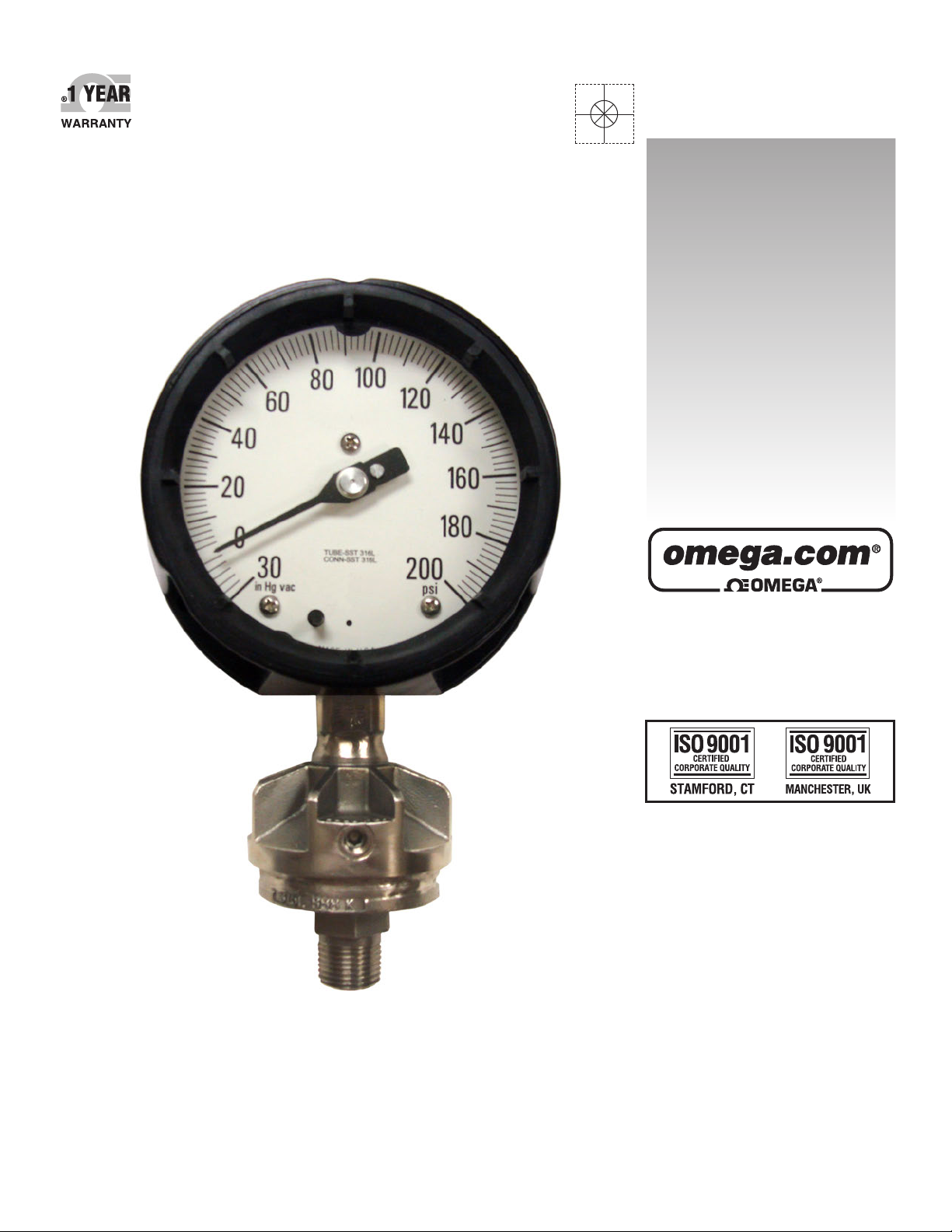
PGR Series
Process Gauge & Diaphragm Seal
Page 2

OMEGAnet®Online Service Internet e-mail
omega.com info@omega.com
Servicing North America:
U.S.A.: Omega Engineering, Inc., One Omega Drive, P.O. Box 4047
ISO 9001 Certie d Stamford, CT 06907-0047 USA
Toll Free: 1-800-826-6342 TEL: (203) 359-1660
FAX: (203) 359-7700 e-mail: info@omega.com
Canada: 976 Bergar
Laval (Quebec), Canada H7L 5A1
Toll-Free: 1-800-826-6342 TEL: (514) 856-6928
FAX: (514) 856-6886 e-mail: info@omega.ca
For immediate technical or application assistance:
U.S.A. and Canada: Sales Service: 1-800-826-6342/1-800-TC-OMEGA
Customer Service: 1-800-622-2378/1-800-622-BEST
Engineering Service: 1-800-872-9436/1-800-USA-WHEN
Mexico: En Español: 001 (203) 359-7803 FAX: (001) 203-359-7807
info@omega.com.mx e-mail: espanol@omega.com
®
®
®
Servicing Europe:
Benelux:Managed by the United Kingdom Office
Toll-Free: 0800 099 3344 TEL: +31 20 347 21 21
FAX: +31 20 643 46 43 e-mail: sales@omega.nl
Czech Republic: Frystatska 184
733 01 Karviná, Czech Republic
Toll-Free: 0800-1-66342 TEL: +420-59-6311899
FAX: +420-59-6311114 e-mail: info@omegashop.cz
France: Managed by the United Kingdom Office
Toll-Free: 0800 466 342 TEL: +33 (0) 161 37 29 00
FAX: +33 (0) 130 57 54 27 e-mail: sales@omega.fr
Germany/Austria: Daimlerstrasse 26
D-75392 Deckenpfronn, Germany
Toll-Free: 0 800 6397678 TEL: +49 (0) 7059 9398-0
FAX: +49 (0) 7056 9398-29 e-mail: info@omega.de
United Kingdom: OMEGA Engineering Ltd.
ISO 9001 Certie d One Omega Drive, River Bend Technology Centre, Northbank
Irlam, Manchester M44 5BD England
Toll-Free: 0800-488-488 TEL: +44 (0)161 777-6611
FAX: +44 (0)161 777-6622 e-mail: sales@omega.co.uk
It is the policy of OMEGA Engineering, Inc. to comply with all worldwide safety and EMC/EMI
regulations that apply. OMEGA is constantly pursuing certification of its products to the European New
Approach Directives. OMEGA will add the CE mark to every appropriate device upon certification.
The information contained in this document is believed to be correct, but OMEGA accepts no liability for any
errors it contains, and reserves the right to alter specifications without notice.
WARNING: These products are not designed for use in, and should not be used for, human applications.
Page 3

WARNING - Misuse of this product may cause explosion and personal injury. Do not use without first reading and understanding
these instructions and the apparatus installation and operating instructions.
The following information on installation and use has been excerpted from ASME B40.100-2005 incorporated in ASME B40.100-2005. The complete ASME B40.100-2005 standard which contains
USE AND INSTALLATION OF PRESSURE GAUGES
additional information may be obtained from the American Society of Mechanical Engineers, 22 Law Drive, Box 2300, Fairfield, NJ 07007-2300.
3.3.5 Pressure Connection
3.3.5.1 Location of Connection
(a) stem mounted - bottom or back
(b) surface mounted - bottom or back
(c) flush mounted - back
3.3.5.2 Type of Connection. Taper pipe
connections for pressures up through 20,000
psi or 160,000 kPa are usually 1/8-27NPT,
1/4-18NTP, or 1/2-14NPT American Standard
external or internal taper pipe threads per
ASME B1.20.1. as required. Above this pressure, 1/4 high pressure tubing connections, or
equal, may be used. Other appropriately sized
connections, employing sealing means other
than tapered threads, are acceptable.
In applications of stem mounted gauges,
especially with liquid filled cases and where
vibration is severe, consideration should be
given to the possibility of failure of the stem or
associated piping caused by the vibrating mass
of the gauge. A large connection (e.g., 1/2NPT
instead of 1/4NPT) or a stronger stem material
(e.g., stainless steel instead of brass), or both,
should be considered.
3.4.1.10 Mounting a pressure gauge in a position other than that at which it was calibrated
can affect its accuracy. Normal calibration position is upright and vertical. For applications
requiring mounting in other than this position,
notify the supplier.
3.4.1.12 Caution to Users.
Pressure gauges can be rendered inaccurate
during shipment despite care taken in packaging. To ensure conformance to the standard
grade to which the pressure gauge was manufactured, it should be checked before use.
4 SAFETY
4.1 Scope
This Section of the Standard presents certain
information to guide users, suppliers, and
manufacturers toward minimizing the hazards
that could result from misuse or misapplication
of pressure gauges with elastic elements. The
user should become familiar with all sections
of this Standard, as all aspects of safety cannot be covered in this Section. Consult the
manufacturer or supplier for advice whenever
there is uncertainty about the safe application
of a pressure gauge.
4.2 General Discussion
4.2.1 Adequate safety results from intelligent
planning and careful selection and installation
of gauges into a pressure system. The user
should inform the supplier of all conditions
pertinent to the application and environment
so that the supplier can recommend the most
suitable gauge for the application.
4.2.2 The history of safety with respect to
the use of pressure gauges has been excellent.
Injuries to personnel and damages to property
have been minimal. In most instances, the
cause of failure has been misuse or misapplication.
4.2.3 The pressure sensing element in most
gauges is subjected to high internal stresses,
and applications exist where the possibility of
catastrophic failure is present. Pressure regulators, diaphragm (chemical) seals, pulsation
dampers or snubbers, syphons, and other similar items, are available for use in these potentially hazardous systems. The hazard potential
increases at higher operating pressure.
4.2.4
The following systems are considered
potentially hazardous and must be carefully
evaluated:
(a) compressed gas systems
(b) oxygen systems
(c) systems containing hydrogen or free
hydrogen atoms
(d) corrosive fluid systems (gas and liquid)
(e) pressure systems containing any explosive
or flammable mixture or medium
(f) steam systems
(g) nonsteady pressure systems
(h) systems where high overpressure could be
accidentally applied
(i) systems wherein interchangeability of
gauges could result in hazardous internal
contamination or where lower pressure
gauges could be installed in higher
pressure systems
(j) systems containing radioactive or toxic
fluids (liquids or gases)
(k) systems installed in a hazardous
environment
4.2.5 When gauges are to be used in contact
with media having known or uncertain corrosive effects or known to be radioactive,
random or unique destructive phenomena can
occur. In such cases the user should always
furnish the supplier or manufacturer with information relative to the application and solicit
his advice prior to installation of the gauge.
4.2.6 Fire and explosions within a pressure
system can cause pressure element failure with
very violent effects, even to the point of completely disintegrating or melting the pressure
gauge. Violent effects are also produced when
failure occurs due to:
(a) hydrogen embrittlement;
(b) contamination of a compressed gas;
(c) formation of acetylides;
(d) weakening of soft solder joints by steam
or other heat sources;
(e) weakening of soft soldered or silver
brazed joints caused by heat sources
such as fires;
(f) corrosion;
(g) fatigue;
(h) mechanical shock;
(i) excessive vibration.
Failure in a compressed gas system can be
expected to produce violent effects.
4.2.7 Modes of Pressure Gauge Failure
4.2.7.1 Fatigue Failure. Fatigue failure
caused by pressure induced stress generally
occurs from the inside or the outside along
a highly stressed edge radius, appearing as
a small crack that propagates along the edge
radius. Such failures are usually more critical
with compressed gas media than with liquid
media.
Fatigue cracks usually release the media fluid
slowly so case pressure buildup can be averted
by providing pressure relief openings in the
gauge case. However, in high pressure elastic
elements where the yield strength approaches
the ultimate strength of the element material,
IMPORTANT - Read other side for additional instructions and warnings.
fatigue failure may resemble explosive failure.
A snubber (restrictor) placed in the gauge
pressure inlet will reduce pressure surges
and restrict fluid flow from the partially open
elastic element.
4.2.7.2 Overpressure Failure. Overpressure
failure is caused by the application of internal
pressure greater than the rated limits of the
elastic element and can occur when a low
pressure gauge is installed in a high pressure
port or system. The effects of overpressure
failure, usually more critical in compressed
gas systems than in liquid filled systems,
are unpredictable and may cause parts to
be propelled in any direction. Cases with
pressure relief openings will not always retain
expelled parts.
Placing a snubber (restrictor) in the pressure gauge inlet will not reduce the immediate
effect of failure, but will help control flow of
escaping fluid following rupture and reduce
the potential of secondary effects.
It is generally accepted that solid front cases
with pressure relief back will reduce the possibility of parts being projected forward in the
event of failure.
The window alone will not provide
adequate protection against internal case pressure buildup, and can be the most hazardous
component.
Short duration pressure impulses (pressure
spikes) may occur in hydraulic or pneumatic
systems, especially when valves open or close.
The magnitude of the spikes may be many
times the normal operating pressure, and may
not be indicated by the gauge. The result
could be immediate failure, or a large upscale
error. A snubber (restrictor) may reduce the
magnitude of the pressure transmitted to the
elastic element.
4.2.7.3 Corrosion Failure. Corrosion
failure occurs when the elastic element has
been weakened through attack by corrosive
chemicals present in either the media inside or
the environment outside it. Failure may occur
as pin-hole leakage through the element walls
or early fatigue failure due to stress cracking
brought about by chemical deterioration or
embrittlement of the material.
A diaphragm (chemical) seal should be considered for use with pressure media that may
have a corrosive effect on the element.
4.2.7.4 Explosive Failure. Explosive failure
is caused by the release of explosive energy
generated by a chemical reaction such as can
result when adiabetic compression of oxygen
occurs in the presence of hydrocarbons. It
is generally accepted that there is no known
means of predicting the magnitude of or
effects of this type of failure. For this mode
of failure, a solid wall or partition between the
elastic element and the window will not necessarily prevent parts being projected forward.
Vibration Failure. The most com-
4.2.7.5
mon mode of vibration failure is movement
parts wear because of high cyclic loading
caused by vibration, resulting in gradual loss
of accuracy, and, ultimately failure of the
pointer to indicate any pressure change.
4.2.7.6 Vibration-Induced Fatigue Failure.
In addition to its effect of the gauge movement
and linkage (see para. 4.2.7.5) vibration may,
in some instances, result in high loading of
various parts of the pressure element assembly.
This loading could cause cracks in the element
itself, or in joints. Case pressure buildup may
be slow, but it is possible that a large hole may
suddenly develop, with a high rate of case
pressure rise, which could result in a failure
similar to an explosive failure.
4.2.8 Pressure Connection. See recom-
mendations in para. 3.3.5.
4.3 Safety Recommendations
4.3.1 Operating Pressure. The pressure
gauge selected should have a full scale pressure such that the operating pressure occurs in
the middle half (25 to 75%) of the scale. The
full scale pressure of the gauge selected should
be approximately two times the intended
operating pressure.
Should it be necessary for the operating
pressure to exceed 75% of full scale, contact
the supplier for recommendations.
This does not apply to test, retarded, or suppressed scale gauges.
4.3.2 Use of Gauges Near Zero Pressure
The use of gauges near zero pressure is not
recommended because the accuracy tolerance
of the gauge may be a large percentage of the
applied pressure. If for example, 1 0/100 psi
Grade A gauge is used to measure 4 psi, the
accuracy of measurement will be +/- 2 psi, or
50% of the applied pressure.
For this reason, gauges should not be used
for the purposes of indicating the residual
pressure in a tank, autoclave, or other similar
device which has been seemingly exhausted.
Depending on the accuracy and the range of
the gauge, hazardous pressure may remain in
the tank even thought the gauge is indicating
zero pressure. The operator may develop
a false sense of security when the gauge
indicates zero or near-zero pressure even
though there may be substantial pressure in
the system. A venting device must be used
to completely reduce the pressure to zero
before unlocking covers, removing fittings, or
performing other similar activities.
4.3.3 Compatibility With Medium
4.3.3.1 Wetted Parts
The elastic element is generally a thin-walled
member, which of necessity operates under
high stress conditions and must; therefore, be
carefully selected for compatibility with the
medium being measured. None of the common element materials is impervious to every
type of chemical attack. The potential for
corrosive attack is established by many factors,
including the concentration, temperature, and
contamination of the medium. The user should
inform the gauge supplier of the installation
conditions so that the appropriate element
material can be selected.
4.3.4 In addition to the factors discussed
above, the capability of a pressure element is
influenced by the design, material and fabrication of the joints between its parts.
(Excerpts from ASME B40.100-2005 continue on back)
Page 4

Common methods of joining are soft soldering, silver brazing, and welding. Joints can be affected by temperature, stress, and corrosive media. Where application questions arise, these factors
should be considered and discussed by the user and supplier.
4.3.5 Some special applications require that the pressure element assembly have a high degree of
leakage integrity. User should contact the supplier to assure that the allowable leakage rate is not
exceeded.
4.3.6 Cases
4.3.6.1 Case, Solid Front. It is generally accepted that a solid front case per para. 3.3.1 will
reduce the possibility of parts being projected forward in the event of elastic element assembly
failure. An exception is explosive failure of the elastic element assembly.
4.3.6.2 Cases, Liquid Filled. It has been general practice to use glycerine or silicone filling
liquids. These fluids must be avoided where strong oxidizing agents, including, but not limited to,
oxygen, chlorine, nitric acid, and hydrogen peroxide are involved. In the presence of oxidizing
agents, potential hazard can result from chemical reaction, ignition, or explosion. Completely
fluorinated or chlorinated fluids or both, may be more suitable for such applications.
The user shall furnish detailed information relative to the application of gauges having liquid
filled cases and solicit the advice of the gauge supplier prior to installation.
In a compressed gas application consideration should also be given to the instantaneous hydraulic effect that may be created by one of the modes of failure outlined in para 4.2.7. The hydraulic
effect due to pressure element failure could cause the window to be projected forward even when a
case having a solid front is employed.
4.3.7 Snubber Placing a snubber or a restrictor between the pressure connection and the elastic
element will not reduce the immediate effect of failure, but will help reduce flow of escaping fluid
following rupture and reduce the potential of secondary effects.
4.3.8 Specific Service Conditions
4.3.8.1 Specific applications for pressure gauges exist where hazards are known. In many
instances, requirements for design, construction and use of gauges for these applications are speci-
fied by state or federal agencies or Underwriters Laboratories, Inc. Some of these specific service
gauges are listed below. This list is not intended to include all types, and the user should always
advise the supplier for all application details.
In addition to the ASME B40.100-2005 standard, the following additional instructions and warnings should be read and understood before using this product.
A very important aspect of selecting and installing pressure gauges is the consideration of the hazards that
will result in the event the gauge fails. The primary causes of failure are misapplication and/or abuse of the
gauge. Those people who are responsible for the selection and installation of pressure gauges must recognize
conditions which will adversely affect the ability of the gauge to perform its function or which will lead to
early failure. These conditions may then be discussed with the supplier to obtain their recommendations.
Failure may constitute:
1. Loss of accuracy.
2. Clogging of the pressure port, or damage to the internal mechanism so that there is either:
a. no indication when pressure is applied or
b. there is an indication of pressure even though none is applied.
3. A leak in the pressure containing parts or joints.
4. A crack or fatigue failure of the bourdon.
5. Bursting of the bourdon due to severe overpressure.
6. An explosion with the system due to a chemical reaction of the pressure medium with contaminants
cause the bourdon to explode.
When specifying, using or installing a pressure gauge, the following factors must be given attention:
1. Operating Pressure
Do not continuously operate the gauge at more than 75% of the span. Bourdon tubes are necessarily highly
stressed, especially in ranges over 1000 psi and continuous operation at full scale will result in early fatigue
failure and subsequent rupture.
2. Materials
Be certain the materials of the pressure containing portions of the gauge are compatible with the pressurized
medium. Gauges are commonly made of copper alloys (brass, bronze, etc.) and may be subject to stress corrosion or chemical attack. Bourdons have relatively thin walls, and the accuracy of the indication is directly
affected by any reduction in the wall thickness. Use of the same material for bourdon as used for the tank or
associated piping is not necessarily good practice. A material having a corrosion rate of .001”/year may be
suitable for the piping, but will be entirely unsuitable for a bourdon having a wall thickness of, for example,
.008 inches. It is imperative that the proper bourdon material be selected for the service on which the gauge
is used. Gauges specifically constructed for corrosion services are available.
3. Cyclic Pressure and Vibration
Continuous, rapid pointer motion will result in excessive war of the internal mechanism and cause gross
errors in the pressure indicated and possibly early fatigue failure of the bourdon. If the pointer motion is due
to mechanical vibration, the gauge must be remotely mounted on a non-vibrating surface and connected to
the apparatus by flexible tubing. If the pointer motion is due to pressure pulsations, a suitable damper must
be used between the pressure source and the gauge.
4. Fatigue
As with any spring, the bourdon will fail after extended use and release the pressurized medium. The larger
the number of applied pressure cycles and the greater the extent of the pressure cycle, the earlier failure will
occur. The fatigue failure may be explosive. Since such a failure will be hazardous to personnel or property,
precautions must be taken to contain or direct the release of the pressurized medium in a safe manner.
4.3.8.2 Acetylene Gauge. A gauge designed to indicate acetylene pressure (and other gases having similar properties). The gauge may bear the inscription ACETYLENE on the dial.
4.3.8.3 Ammonia Gauge. A gauge designed to indicate ammonia pressure and to withstand corrosive effects of ammonia. The gauge may bear the inscription AMMONIA or NH3 on the dial. It
should also include the equivalent saturation temperature scale markings on the dial. Materials such
as copper, brass, and silver brazing alloys should not be used.
4.3.8.4 Chemical Gauge. A gauge designed to indicate the pressure of corrosive or high viscosity
fluids, or both. The primary material(s) in contact with the pressure medium may be identified on
the dial. It may be equipped with a diaphragm (chemical) seal, pulsation damper, or pressure relief
device, or a combination. These devices help to minimize potential damage to personnel and property on the event of gauge failure. They may, however, also reduce accuracy or sensitivity, or both.
4.3.8.5 Oxygen Gauge. A gauge designed to indicate oxygen pressure. Cleanliness shall comply
with Level IV (see Section 5). The dial shall be clearly marked with a universal symbol and/or USE
NO OIL in red color (see para. 6.1.1.4).
4.4 Reuse of Pressure Gauges
It is not recommended that pressure gauges be moved from one application to another for the following reasons:
(a) Chemical Compatibility. The consequences of incompatibility can range from contamination
to explosive failure. For example, moving an oil service gauge to oxygen service can result in
explosive failure.
(b) Partial Fatigue. The first installation may involve pressure pulsation that has expended most of
the gauge life, resulting in early fatigue in the second installation.
(c) Corrosion. Corrosion of the pressure element assembly in the first installation may be sufficient
to cause early failure in the second installation.
5. Frequency of Accuracy Evaluation
Where the pressure measurement is critical and gauge failure or gross inaccuracy will result in hazard to
personnel or property, the gauge should be checked for accuracy and proper operation on a periodic basis.
6. Use with Oxygen
Gauges used for measurement of oxygen pressure must be free of contamination within the pressure containing portion. Various levels of cleanliness are specified in ASME B40.1. The gauge itself and the equipment
to which the gauge is attached (pressure regulators, cylinders, etc.) must be kept clean so as not to contaminate the gauge. Filters on the equipment must be examined periodically and cleaned or replaced. The sudden in-rush of a high pressure gas will momentarily create a very high temperature which in the presence of
oxygen may ignite the contaminant causing a violent explosion. Therefore, when the valve on the oxygen
supply tank is opened, to admit oxygen to the regulator, the valve should be opened very slowly so as to
allow the pressure to build up slowly. In order to accomplish this it is recommended that the tank valve be
opened momentarily and the closed snugly but not excessively before attaching the regulator. This will not
only blow out accumulated dirt in the valve, but will also place the valve in a condition that will permit it to
be opened slowly rather than suddenly breaking loose as a result of being closed too tightly. When bleeding
the oxygen tank prior to attaching the regulator, be certain the valve opening is directed away from any open
flame and the operator. When opening the oxygen tank valve, the operator must not stand in front of or
behind the gauge and must wear eye and face protection. In this position if there is an explosion due to
contaminated equipment any particles projected from the gauge will not be propelled directly at the operator.
7. Use with Hydrogen
Steel bourdons including 400 series stainless steel are subject to hydrogen embrittlement when stressed.
Measurement of gas or liquids containing hydrogen (such as natural gas, sour oil) require the use of special
materials for the bourdon.
8. Venting of Case
Vents provided in the pressure gauge case (clearance around pressure connection, rubber grommets, pressure
relief back, etc.) must not be closed or restricted from operating. There is always the possibility that the pressure medium will be admitted to the case interior as a result of a leaking joint or bourdon tube failure. If this
occurs, the pressure medium must be vented from the case so as not to build up sufficient pressure to rupture
the case or window. However, venting will not prevent case rupture in the event of a violent explosion.
9. Liquid Filled Gauges
Performance of pressure gauges used in severe vibration or pulsating pressure service, can be improved by
filling the gauge case with a viscous fluid. Gauges constructed in this manner necessarily require sealed
cases to prevent the escape of the liquid. However, some means of venting the case must be provided. In
some instances this vent is sealed to prevent loss of fluid during shipment, and must be released after the
gauge is installed. Be certain to follow the installation instructions for properly venting the gauge after
installation. The liquid filling most commonly used is a mixture of glycerin and water.
Glycerin can combine with strong oxidizing agents including (but not limited to) oxygen, chlorine,
nitric acid and hydrogen peroxide, and result in an explosion which can cause property damage and
personal injury. If gauges are to be used in such service, do not use glycerin filled gauges; consult the
supplier for proper filling medium.
WARNING - Misuse of this product may cause explosion and personal injury. Do not use without first reading and understanding
these instructions and the apparatus installation and operating instructions.
Important - Read other side for additional instructions and warnings.
Page 5

WARRANTY/ DISCLAIMER
OMEGA ENGINEERING, INC. warrants this unit to be free of defects in materials and workmanship for a
period of 13 months from date of purchase. OMEGA’s WARRANTY adds an additional one (1) month
grace period to the normal one (1) year product warranty to cover handling and shipping time. This
ensures that OMEGA’s customers receive maximum coverage on each product.
If the unit malfunctions, it must be returned to the factory for evaluation. OMEGA’s Customer Service
Department will issue an Authorized Return (AR) number immediately upon phone or written request.
Upon examination by OMEGA, if the unit is found to be defective, it will be repaired or replaced at no
charge. OMEGA’s WARRANTY does not apply to defects resulting from any action of the purchaser,
including but not limited to mishandling, improper interfacing, operation outside of design limits,
improper repair, or unauthorized modification. This WARRANTY is VOID if the unit shows evidence of
having been tampered with or shows evidence of having been damaged as a result of excessive corrosion;
or current, heat, moisture or vibration; improper specification; misapplication; misuse or other operating
conditions outside of OMEGA’s control. Components in which wear is not warranted, include but are not
limited to contact points, fuses, and triacs.
OMEGA is pleased to offer suggestions on the use of its various products. However,
OMEGA neither assumes responsibility for any omissions or errors nor assumes liability for any
damages that result from the use of its products in accordance with information provided by
OMEGA, either verbal or written. OMEGA warrants only that the parts manufactured by the
company will be as specified and free of defects. OMEGA MAKES NO OTHER WARRANTIES OR
REPRESENTATIONS OF ANY KIND WHATSOEVER, EXPRESSED OR IMPLIED, EXCEPT THAT OF
TITLE, AND ALL IMPLIED WARRANTIES INCLUDING ANY WARRANTY OF MERCHANTABILITY
AND FITNESS FOR A PARTICULAR PURPOSE ARE HEREBY DISCLAIMED. LIMITATION OF
LIABILITY: The remedies of purchaser set forth herein are exclusive, and the total liability of
OMEGA with respect
indemnification, strict liability or otherwise, shall not exceed the purchase price of the
component upon which liability is based. In no event shall OMEGA be liable for
consequential, incidental or special damages.
CONDITIONS: Equipment sold by OMEGA is not intended to be used, nor shall it be used: (1) as a “Basic
Component” under 10 CFR 21 (NRC), used in or with any nuclear installation or activity; or (2) in medical
applications or used on humans. Should any Product(s) be used in or with any nuclear installation or
activity, medical application, used on humans, or misused in any way, OMEGA assumes no responsibility
as set forth in our basic WARRANTY/ DISCLAIMER language, and, additionally, purchaser will indemnify
OMEGA and hold OMEGA harmless from any liability or damage whatsoever arising out of the use of the
Product(s) in such a manner.
to this order, whether based on contract, warranty, negligence,
RETURN REQUESTS/INQUIRIES
Direct all warranty and repair requests/inquiries to the OMEGA Customer Service Department. BEFORE
RETURNING ANY PRODUCT(S) TO OMEGA, PURCHASER MUST OBTAIN AN AUTHORIZED RETURN
(AR) NUMBER FROM OMEGA’S CUSTOMER SERVICE DEPARTMENT (IN ORDER TO AVOID
PROCESSING DELAYS). The assigned AR number should then be marked on the outside of the return
package and on any correspondence.
The purchaser is responsible for shipping charges, freight, insurance and proper packaging to prevent
breakage in transit.
FOR WARRANTY
following information available BEFORE
contacting OMEGA:
1. Purchase Order number under which the product
was PURCHASED,
2. Model and serial number of the product under
warranty, and
3. Repair instructions and/or specific problems
relative to the product.
OMEGA’s policy is to make running changes, not model changes, whenever an improvement is possible. This affords
our customers the latest in technology and engineering.
OMEGA is a registered trademark of OMEGA ENGINEERING, INC.
© Copyright 2009 OMEGA ENGINEERING, INC. All rights reserved. This document may not be copied, photocopied,
reproduced, translated, or reduced to any electronic medium or machine-readable form, in whole or in part, without the
prior written consent of OMEGA ENGINEERING, INC.
RETURNS, please have the
FOR NON-WARRANTY REPAIRS,
for current repair charges. Have the following
information available BEFORE contacting OMEGA:
1. Purchase Order number to cover the COST
of the repair,
2. Model and serial number of the product, and
3. Repair instructions and/or specific problems
relative to the product.
consult OMEGA
Page 6

Where Do I Find Everything I Need for
Process Measurement and Control?
OMEGA…Of Course!
Shop online at omega.com
SM
TEMPERATURE
Thermocouple, RTD & Thermistor Probes, Connectors, Panels & Assemblies
Wire: Thermocouple, RTD & Thermistor
Calibrators & Ice Point References
Recorders, Controllers & Process Monitors
Infrared Pyrometers
PRESSURE, STRAIN AND FORCE
Transducers & Strain Gages
Load Cells & Pressure Gage s
Displacement Transducers
Instrumentation & Accessories
FLOW/LEVEL
Rotameters, Gas Mass Flowmeters & Flow Computers
Air Velocity Indicator s
Turbine/Paddlewheel Systems
Totalizers & Batch Controllers
pH/CONDUCTIVITY
pH Electrodes, Testers & Accessories
Benchtop/Laboratory Meters
Controllers, Calibrators, Simulators & Pumps
Industrial pH & Conductivity Equipment
DATA ACQUISITION
Data Acquisition & Engineering Softwar e
Communications-Based Acquisition Systems
Plug-in Cards for Apple, IBM & Compatibles
Datalogging Systems
Recorders, Printers & Plotters
HEATERS
Heating Cabl e
Cartridge & Strip Heaters
Immersion & Band Heaters
Flexible Heaters
Laboratory Heaters
ENVIRONMENTAL
MONITORING AND CONTROL
Metering & Control Instrumentatio n
Refractometers
Pumps & Tubing
Air, Soil & Water Monitor s
Industrial Water & Wastewater Treatment
pH, Conductivity & Dissolved Oxygen Instrument s
M-5165/0612
 Loading...