

Page 1
www.omega.com
e-mail: info@omega.com
User’s Guide
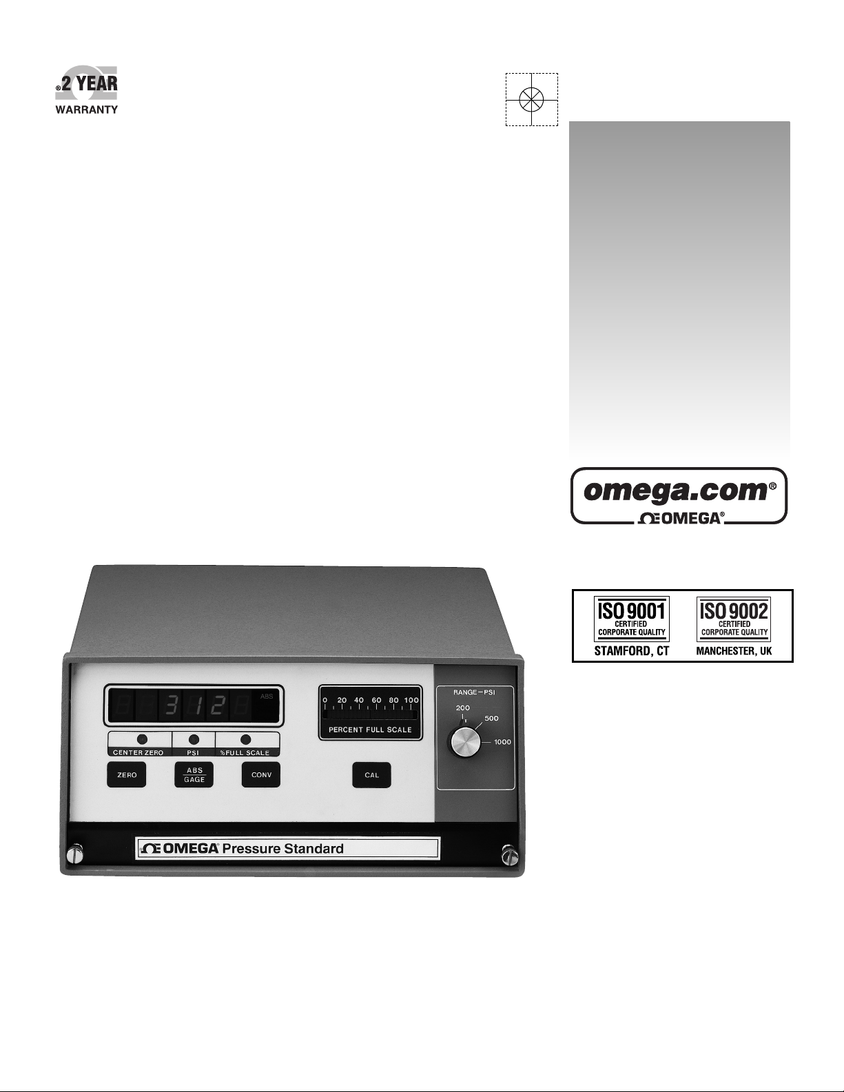
PCL-3000 SERIES
High Accuracy Pressure Standard
Shop online at
Page 2

Servicing North America:
USA: One Omega Drive, P.O. Box 4047
ISO 9001 Certified Stamford CT 06907-0047
TEL: (203) 359-1660 FAX: (203) 359-7700
e-mail: info@omega.com
Canada: 976 Bergar
Laval (Quebec) H7L 5A1, Canada
TEL: (514) 856-6928 FAX: (514) 856-6886
e-mail: info@omega.ca
For immediate technical or application assistance:
USA and Canada: Sales Service: 1-800-826-6342 / 1-800-TC-OMEGA
®
Customer Service: 1-800-622-2378 / 1-800-622-BEST
®
Engineering Service: 1-800-872-9436 / 1-800-USA-WHEN
®
TELEX: 996404 EASYLINK: 62968934 CABLE: OMEGA
Mexico: En Espan˜ ol: (001) 203-359-7803 e-mail: espanol@omega.com
FAX: (001) 203-359-7807 info@omega.com.mx
Servicing Europe:
Benelux: Postbus 8034, 1180 LA Amstelveen, The Netherlands
TEL: +31 (0)20 3472121 FAX: +31 (0)20 6434643
Toll Free in Benelux: 0800 0993344
e-mail: sales@omegaeng.nl
Czech Republic: Frystatska 184, 733 01 Karviná, Czech Republic
TEL: +420 (0)59 6311899 FAX: +420 (0)59 6311114
Toll Free: 0800-1-66342 e-mail: info@omegashop.cz
France: 11, rue Jacques Cartier, 78280 Guyancourt, France
TEL: +33 (0)1 61 37 29 00 FAX: +33 (0)1 30 57 54 27
Toll Free in France: 0800 466 342
e-mail: sales@omega.fr
Germany/Austria: Daimlerstrasse 26, D-75392 Deckenpfronn, Germany
TEL: +49 (0)7056 9398-0 FAX: +49 (0)7056 9398-29
Toll Free in Germany: 0800 639 7678
e-mail: info@omega.de
United Kingdom: One Omega Drive, River Bend Technology Centre
ISO 9002 Certified Northbank, Irlam, Manchester
M44 5BD United Kingdom
TEL: +44 (0)161 777 6611 FAX: +44 (0)161 777 6622
Toll Free in United Kingdom: 0800-488-488
e-mail: sales@omega.co.uk
OMEGAnet®Online Service Internet e-mail
www.omega.com info@omega.com
It is the policy of OMEGA to comply with all worldwide safety and EMC/EMI regulations that
apply. OMEGA is constantly pursuing certification of its products to the European New Approach
Directives. OMEGA will add the CE mark to every appropriate device upon certification.
The information contained in this document is believed to be correct, but OMEGA Engineering, Inc. accepts
no liability for any errors it contains, and reserves the right to alter specifications without notice.
WARNING: These products are not designed for use in, and should not be used for, patient-connected applications.
Page 3

i
TABLE OF CONTENTS
SECTION PAGE
SECTION 1 INTRODUCTION ..................................................................... 1
1.1 General Description ........................................................................................... 1
1.2 Features ............................................................................................................... 1
1.3 Options ................................................................................................................ 1
SECTION 2 INSTALLATION ....................................................................... 2
2.1 Unpacking ........................................................................................................... 2
2.2 Mounting ............................................................................................................. 2
2.3 117/220 Vac Operation ..................................................................................... 2
2.4 Rear Panel Connections ..................................................................................... 3
SECTION 3 OPERATION ............................................................................4
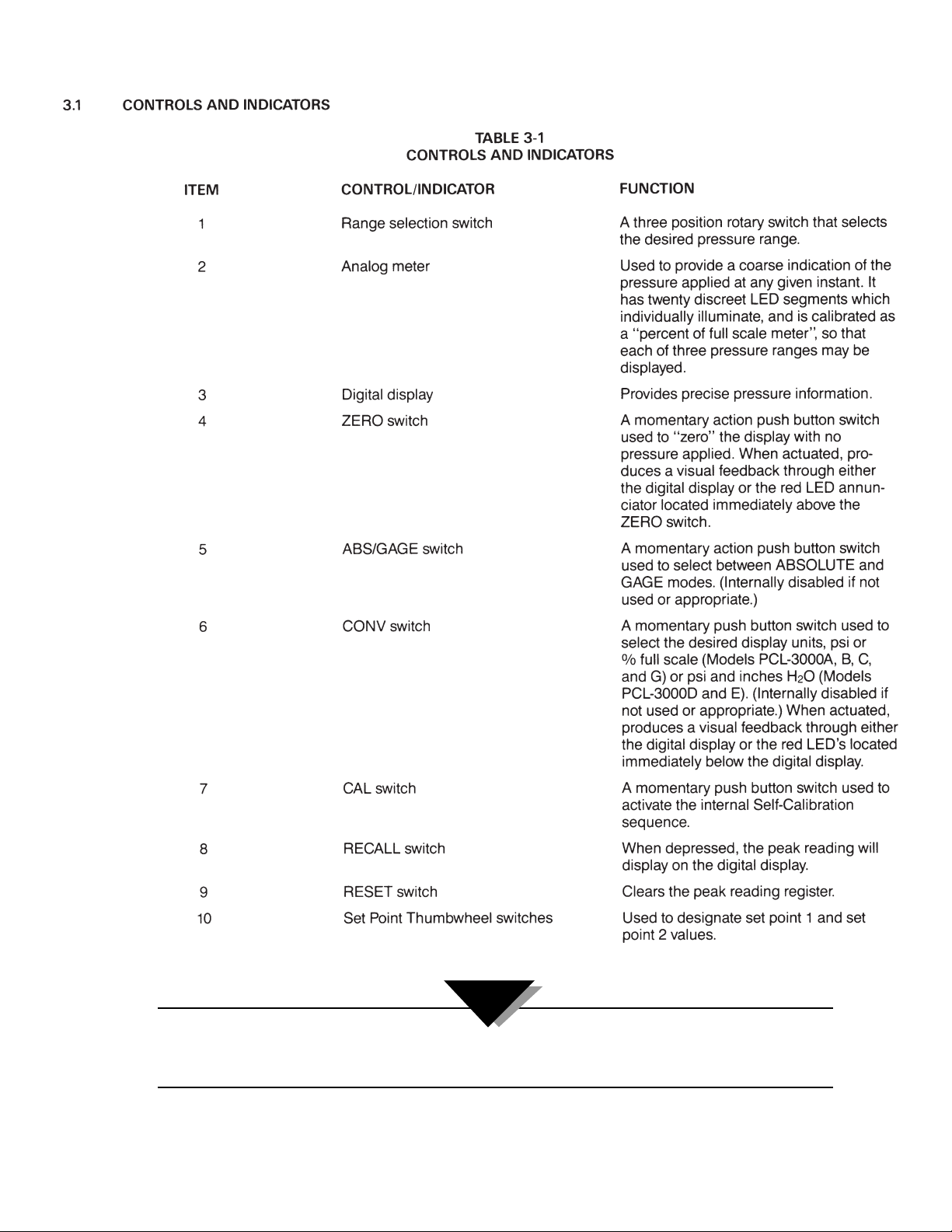
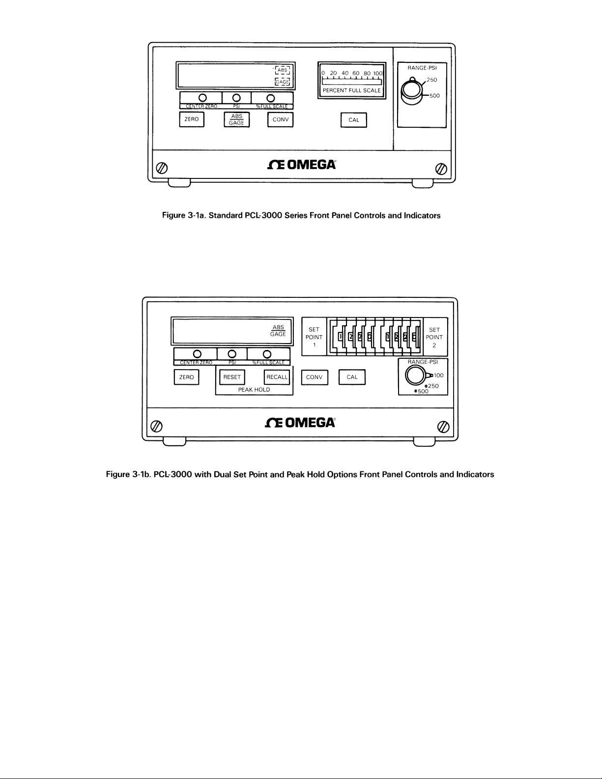
3.1 Controls and Indicators ..................................................................................... 4
3.2 Operating Procedure ......................................................................................... 5
3.3 Configuration Switch Settings ......................................................................... 6
3.3.1 ABS/Gage/Peak Hold Select ........................................................................... 7
3.3.1.1 Freeze Mode ........................................................................................................ 7
3.3.2 Convert Enable ................................................................................................... 8
3.3.3 Digital Averaging ............................................................................................... 8
3.3.4 Automatic Zero Maintenance (AZM) Enable ................................................ 8
3.3.5 Automatic Span Maintenance (ASM) Enable ................................................ 9
SECTION 4 THEORY OF OPERATION ......................................................... 9
SECTION 5 CALIBRATION ....................................................................... 10
5.1 General ................................................................................................................10
5.2 Calibration Set-Up ........................................................................................... 10
5.3 Instrument Set-Up ............................................................................................ 10
5.4 Zero/Span Calibration (Each Range) ............................................................ 11
5.5 Linearity and Hysteresis Calibration (Each Range) .................................... 12
5.6 Shunt Resistor Calibration .............................................................................. 13
5.7 Permanent Data Storage .................................................................................. 14
SECTION 6 SPECIFICATIONS ................................................................... 14
Page 4

1
SECTION 1 INTRODUCTION
1.1 GENERAL DESCRIPTION
The OMEGA®PCL-3000 Series Digital Pressure Standards are specifically designed for use in the manufacture,
test or calibration of pressure sensitive devices. Using a patented, bonded foil strain gage sensor and advanced
microcircuitry these rugged, compact instruments provide simultaneous digital and analog readouts of the
pressures applied.
Standard front panel switches permit desired pressure range selection, automatic zeroing of the display, and
actuation of a unique internal self-calibration feature.
Each instrument has two displays - digital and analog. The digital display provides precise pressure information,
and the analog display gives quick reference to direction and level of pressure.
1.2 FEATURES
• Three, independent, switch selectable pressure ranges per instrument
• Accuracy of each range equal to or better than +0.5% F. S.
• Both GAGE and ABSOLUTE pressure calibrations available via front panel switch selection (for applicable
models)
• Automatic Self-Calibration: Computer controlled internal circuitry provides automatic maintenance of both
zero and span calibration data to insure long term stability and accuracy. No potentiometer adjustments used
or required. Calibration of all three ranges completed within six seconds.
• Calibration Integrity: Tamper-proof design. Once calibrated, numerous “safe guards” guarantee the integrity of
pressure readings obtained. Display “prompting” provides operator with functional status information during
both operation and calibration.
• Digital Display: Eliminates parallax, interpolation and operator judgement errors. Large, bright red LED digits
provide excellent readability under all lighting conditions.
• Analog Display: An electronic, front panel meter provides instantaneous visual indication of applied pressure.
• Fast response - pressure data refreshed 10 times per second
• Pressure media - any gas or fluid compatible with 17-4PH stainless steel alloy
• Data output is Serial data, 20 mA loop current, ASCII code, supplied as standard interface
1.3 OPTIONS
ANALOG OUTPUT:
Either a 0 to 10 Vdc or a 4 to 20 mA isolated output is available. Both outputs are optically isolated from the input
circuitry and the external case. The accuracy is ±0.25% F. S. maximum.
PARALLEL BCD DATA OUTPUT:
This output is isolated, tri-state buffered and DTL/TTL compatible. The data consists of; polarity, five full data
digits, measurement units, data valid, hold and enable lines.
RS-232 SIMPLEX OUTPUT:
Available with BAUD Rate Select from 300 to 9600 BAUD, two different formats -computer or printer; and two
different request modes - demand or continuous. A program sheet is supplied by the factory when this option is
ordered.
PEAK HOLD:
This option retains the maximum pressure value in memory. Depressing the RECALL switch on the front panel
will display the peak reading. Depressing the RESET switch clears the peak reading register.
SETPOINT OUTPUT:
Up to two independent set points can be programmed and provided for the purpose of implementing various
control functions. These set points may be programmed or changed either via internal switch settings or by the
operator.
Solid state, optically isolated relay output contacts rated at 120/240 Vac and 1.5 A are provided for control.
Relays may be programmed to be either OPEN or CLOSED below the set point activation level.
BATTERY OPERATION:
This internal self-contained rechargeable battery provides eight hours of continuous service. A low battery light
(lower righthand corner of front panel) indicates when it’s time to recharge the batteries.
PANEL MOUNTING KIT: This optional side-mounting kit allows recessed mounting into a custom fit panel.
FREEZE MODE:
When connected via terminal board, TB-2 pins 7 and 8, display data will be momentarily (approximately 5
seconds) frozen when external switch contacts change state
Page 5
2
SECTION 2 INSTALLATION
2.1 UNPACKING
Remove the Packing List and check off actual equipment received. If there are any questions about the shipment,
please call the OMEGA Customer Service Department at 1-800-622-2378 or (203) 359-1660. We can also be
reached on the Internet at:
www.omega.com
e-mail: info@omega.com
Upon receipt of shipment, inspect the container and equipment for any signs of damage. Take particular note of
any evidence of rough handling in transit. Immediately report any damage to the shipping agent.
The carrier will not honor any claims unless all shipping material is saved for their examination. After examining
and removing contents, save packing material in the event reshipment is necessary.
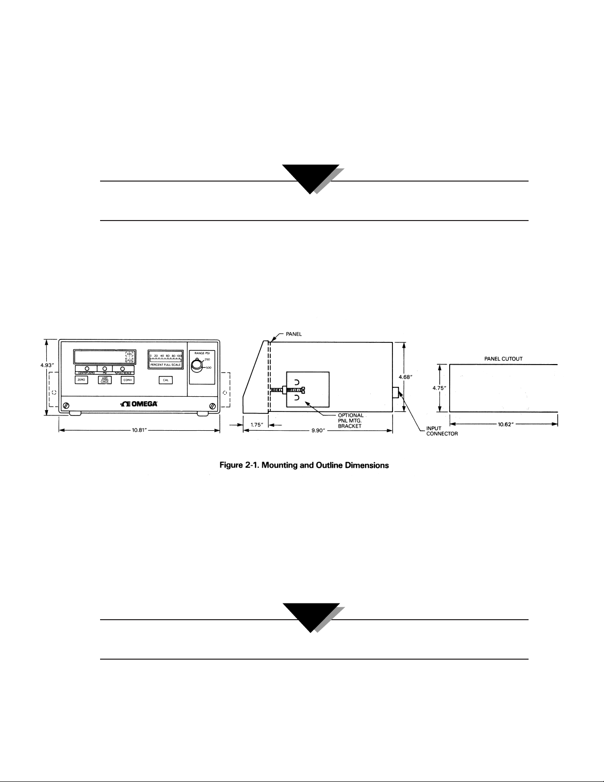
2.2 MOUNTING
The PCL-3000 Series comes standard for table-top usage, with rubberized feet and a tilt stand. With the optional
Panel Mounting Kit, the PCL-3000 can be panel-mounted through panels of any thickness up to 11⁄4 inches. Panel
cutout dimensions and overall unit dimensions are shown in Figure 2-1.
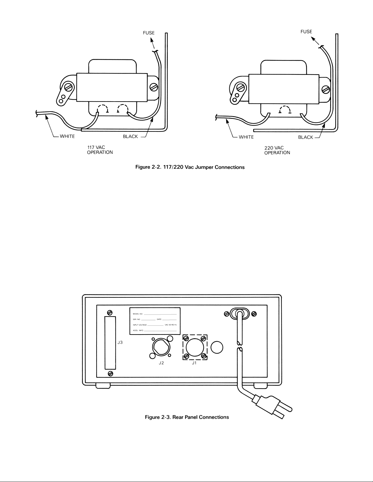
2.3 117/220 VAC OPERATION
The PCL-3000 is supplied with a multi-tap power transformer primary winding such that input voltages of 117
Vac or 220 Vac, 50/60 Hz may be used for excitation.
The unit will be shipped from the factory with the voltage set according to the customer order, and the
0PCL-3000’s rear panel nameplate will reflect this voltage.
To change the operational voltage:
1. Loosen the two thumbscrews located at the bottom outermost corners of the front panel, then slide the
electronic assembly forward.
The PCL-3000 may be fully operated with the case removed without any potentially lethal shock hazard to
operating personnel, since the highest accessible internal voltage is nominally 25 Vdc.
2. Remove the two screws which hold the line voltage filter to the rear panel. Leave all the wires connected and
simply fold them out of the way temporarily.
3. Carefully remove and save the protective insulating cover sheet from the top of the transformer.
4. Refer to Figure 2-2 and make the appropriate transformer connections via jumpers.
NOTE:
NOTE:
Page 6
3
2.4 REAR PANEL CONNECTIONS
The rear panel (refer to Figure 2-3) contains the power line input receptacle, the pressure port fitting, the unit’s
identification plate, and if required, either one or both option connectors, J1 and J3. The J1 connector is for either
of the Analog Output options and the RS-232 option. The J3 connector is for the Parallel BCD Output option. The
pressure port is a male, 7/16-20 UNF-2A fitting.
Page 7
4
Some configurations require that certain switches be inactive. For example, the ABS/GAGA switch is not required if
the unit is configured for “gage only” operation. If so, the affected switch will be internally programmed to be
inactive and a “blank” overlay will be used to cover the switch nomenclature.
NOTE:
SECTION 3 OPERATION
Page 8
5
3.2 OPERATING PROCEDURE
1. Apply power to the instrument and allow to stabilize for at least 20 minutes. If possible, the unit should have
power applied continuously.
2. Connect the pressure source to the instrument via the male, 7/16-20 UNF-2A fitting provided on the rear
panel. Valves for venting and applying the pressure should be provided.
3. Select the desired full scale pressure range via the three position RANGE-PSI Switch. Do not change pressure
ranges during any given pressure cycle.
4. If applicable or required, select the GAGE mode of operation by momentarily depressing the ABS/GAGE push
button switch.
5. To zero the instrument, vent the input pressure port to atmosphere (0 PSIG) and momentarily depress the
ZERO push button switch.
The display will indicate “zero” and the CENTER ZERO annunciator (LED) will illuminate.
Page 9
6
6. To perform a self-calibration check simply set the instrument to zero as per step 5 and momentarily depress the
CAL switch.
The display will immediately blank except for two “- -” which indicate the unit is performing the selfcalibration. If the calibration is correct, a 100.00 indication will be momentarily displayed and then the display
will revert to its normal “zero” indication.
7. To select the desired measurement display units (psi, % full scale, or inches H20) depress the CONV push
button switch.
8. The instrument is now fully calibrated and ready to display applied pressure.
Application of pressures greater than 1.5 times the highest pressure range value of the indicator may cause
calibration errors or even permanent damage to the pressure transducer.
3.3 CONFIGURATION SWITCH SETTINGS
As normally supplied, the PCL-3000 will be fully calibrated and configured to the requirements specified by the
customer. However, there are several functions or operational features (covered in paragraphs 3.3.1 through
3.3.5) that may be altered by the operator during usage. These are controlled by the eight position DIP switch, S1
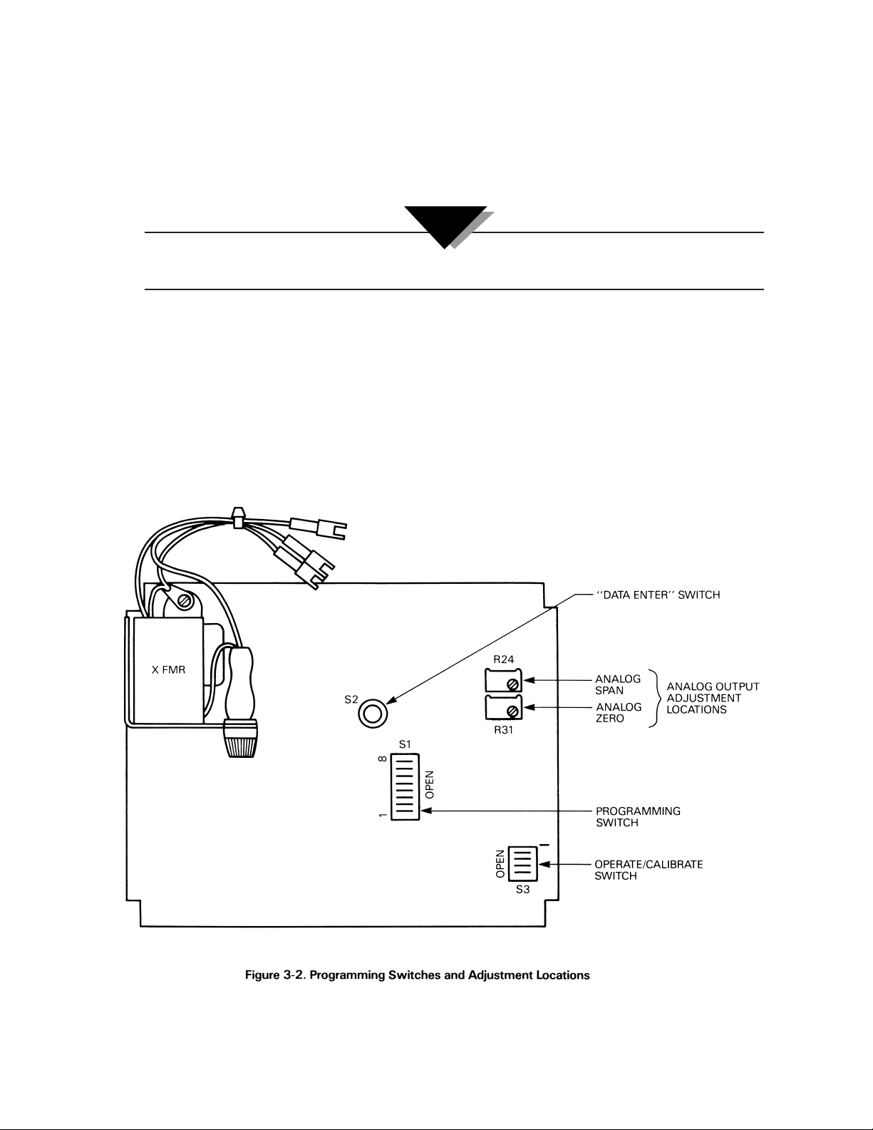
(refer to Figure 3-2). To access S1, loosen the two thumbscrews located at the bottom outermost corners of the
front panel, then slide the electronic assembly forward.
CAUTION:
Page 10

7
0 = Open
1 = Closed
* ABSOLUTE or GAGE modes of operation depend up on the style of transducer supplied and the type of
internal memory configuration utilized.
When the ABS/GAGE switching is not utilized, the front panel push button switch will be programmed to
inactive and covered with a “blank” overlay.
When the PEAK HOLD option is supplied, switching from ABS to GAGE calibration via the front panel is not
possible, and when enabled, the FREEZE MODE (if supplied) is not operable.
When the PEAK HOLD option is supplied it is possible to switch from ABS to GAGE via an internal change. Contact
the OMEGA Engineering Department for additional information.
3.3.1.1 Freeze Mode
The external contacts for the FREEZE MODE input are available via TB-2, pin 7 (+) and pin 8 (ground return).
TB-2 is the orange terminal block located on the right front of the PC Board (refer to Figure 3-3).
NOTE:
Page 11

8
3.3.2 Convert Enable (Refer to Table 3-3)
The PCL-3000 is supplied with the display indication calibrated in PSI (either A or G or both) and capable of
being converted to % of full scale readings (Models PCL-3000A, B, C, and G) or inch H20 (Models PCL-3000D and
E) via the front panel CONV push button switch.
3.3.3 Digital Averaging (Refer to Table 3-4)
Digital averaging is a technique where numerous update cycles are averaged together before the numerical
display data is changed. In essence, this feature acts as a variable rate electronic filter to provide a more stable
pressure indication reading.
The AUTO mode of this filter allows the display to update rapidly (12/sec) when the input pressure is being
quickly changed, and yet provides extremely stable display operation (3/sec) when the desired pressure input
value has been obtained.
3.3.4 Automatic Zero Maintenance (AZM) Enable (Refer to Table 3-5)
The Automatic Zero Maintenance (AZM) feature is used to “hold” the indicator reading to a zero value as long as
the actual pressure input is maintained at zero. If the input pressure changes by more than one half a least
significant display digit between two consecutive display update cycles, the “hold” feature is automatically
disabled and the exact magnitude of the pressure being exerted will be displayed.
In some applications it may be better to operate the instrument without the AZM circuit enabled. If so, pressing
the ZERO push button switch, with zero pressure applied to the instrument, will guarantee that each new
pressure cycle begins at zero.
Page 12

9
3.3.5 Automatic Span Maintenance (ASM) Enable (refer to Table 3-6)
The Automatic Span Maintenance (ASM) circuit operates in conjunction with the front panel CAL button to
provide a calibration feature that insures long term accuracy by utilizing the computer to generate and control an
internal “shunt calibration mode” of operation, where the latest indicator reading obtained is compared against,
and if necessary, corrected to the digitally stored value for the same shunt calibration reading obtained at the
time of initial pressure calibration.
SECTION 4 THEORY OF OPERATION
The heart of the PCL-3000 Series Pressure Indicators is a highly stable and repeatable pressure transducer.
These sensors, which utilize a patented bending beam mechanism operating in conjunction with a bonded metal
foil strain gage bridge, produce an electrical output signal which is linearly proportional to applied pressure.
By combining these sensors with sophisticated microprocessor-based circuitry an even higher degree of
operational accuracy and precision has been accomplished. For example, the unique “push-to-zero” and “zero
tracking” feature permits each new pressure cycle to begin from a known and digitally stored zero reference
value and, eliminates the necessity of the customary “zero” adjustment.
In like manner, the span potentiometer is eliminated since the numerical value corresponding to full scale
pressure is also digitally stored during initial instrument calibration and all subsequent pressurizations are
simply “ratioed” to this value and displayed in the appropriate engineering units. Computer generated and
stored correction curves for both the nonlinearity and the hysteresis of the sensor improve these characteristics
by an order of magnitude or more. Finally, a “self-calibration” feature insures long term accuracy by utilizing the
computer to generate and control an internal “shunt calibration mode” of operation where the indicator’s reading
is compared against, and if necessary, corrected to the digitally stored value for full scale obtained at the time of
initial pressure calibration.
For all its sophistication, however, the instrument is simple to operate and easy to calibrate. Operation of the unit
is completely controlled and performed via the front panel switches and consists basically of the following fourstep sequence:
a. Select the desired pressure range.
b. Vent the transducer system to atmospheric pressure.
c. Press the zero switch*.
d. Close the vent valve and begin pressure measurements.
* If a “self-calibration” cycle is desired - press the CAL switch after completing step c.
With respect to calibration, the units are shipped from the factory fully configured and calibrated to the
requirements of the customer purchase order and should be ready for immediate use after installation.
However, if and when re-calibration is required, the PCL-3000 Series has been designed and programmed to be
very “user friendly” in that it provides the calibrator with various prompting symbols and legends during each
phase of the calibration cycle.
To prevent unauthorized tampering or misalignment, numerous safe guards have been incorporated which
greatly minimizes this potential danger.
Page 13

10
SECTION 5 CALIBRATION
5.1 GENERAL
The following calibration sequence will permit a qualified technician to calibrate the PCL-3000. It must be
emphasized that when performing the calibration procedures, that the computer within the PCL-3000 is actually
being reprogrammed.
Therefore, it is imperative that the test equipment being used is in satisfactory operating condition, and that the
technician fully understands its operational characteristics and methods of usage. In addition, the PCL-3000 must
be properly warmed up and electrically stabilized prior to performing a calibration cycle.
5.2 CALIBRATION SET-UP
Figure 5-1 illustrates a typical calibration set-up using a floating piston type air dead weight tester. (Any type of
precision source is acceptable as long as its basic accuracy is ±0.025% of point or better.)
To permit proper calibration, at least an on/off and a vent valve, connected as shown in Figure 5-1, must be
provided.
5.3 INSTRUMENT SET-UP
To place the PCL-3000 into its calibrate mode, temporarily remove the instrument from its case by loosening the
two thumbscrews at the bottom outermost corners of the front panel and sliding the electronic assembly forward.
Locate the four-position DIP switch, S3 (refer to Figure 3-2) and set the switches according to Table 5-1.
Page 14

11
In the calibrate mode the indicators numerical display is used to provide operator prompting symbols as well as
displaying the various data formats employed. In addition, the front panel ABS/GAGE push button switch
becomes a sequential “ stepper” used to select the various programming functions (zero/span;
linearity/hysteresis; shunt calibration) and the CAL push button switch is used as an “enter” key.
All calibration functions will be performed as “gage” (atmospheric reference) measurements unless the
instrument being calibrated has been configured as an “absolute only” unit. If so, the following procedures are
still valid except that an absolute (“0” PSIA) reference must be used.
Figure 5-2 illustrates the location of the “stepper” and “enter” key as well as showing the display format obtained
as soon as the unit has been placed in the calibrate mode.
5.4 ZERO/SPAN CALIBRATION (EACH RANGE)
Pressing the “stepper” push button once places the PCL-3000 into its ZERO/SPAN calibration mode. The display
will be as shown in Figure 5-3.
Starting with the PCI-3000’s lowest pressure range, sequentially perform steps 1 and 2 shown in Table 5-2 for
each pressure range. Perform the following for each step in Table 5-2:
1. Adjust the input pressure to the appropriate (either 0 or 100%) value.
2. Perform the action indicated by Table 5-2 when pressure input readings are stable.
Page 15

12
NOTES:
1. If readings are not stable or are not within ±20% of zero, the zero correction cannot be entered.
2. If readings are not stable or are not within ± 5% of 100%, the span correction cannot be entered.
5.5 LINEARITY AND HYSTERESIS CALIBRATION (EACH RANGE)
For normal re-calibration cycles this section of the procedure can usually be omitted and the calibrating technician
may move directly to paragraph 5.6.
Normally the linearization and hysteresis corrections are not required because for any given sensor, once the
correction factors have been programmed (initially, during factory calibration) they almost never change unless the
sensor itself has been replaced or severely overpressurized during usage.
If it is necessary or desirable to perform the Linearity and Hysteresis Calibration sequence proceed as follows.
Actuating the “stepper” push button once again places the indicator into its LINEARIZATION/HYSTERESIS
calibration mode. The display will be as shown in Figure 5-4.
Starting with the PCL-3000’s lowest pressure range, sequentially perform the twelve steps described in Table 5-3
for each pressure range being calibrated. Perform the following for each step:
1. Adjust the input pressure to the appropriate value without overshooting the setting. Overshoots of up to one
percent are acceptable.
2. Perform the action as indicated in Table 5-3 when the readings are stable.
NOTE:
Page 16

13
NOTES:
1. If the reading in motion or the correction required is not within ±0.8% of full scale, no entry will be made.
2. If the entry is valid, the display will momentarily indicate the correction value (in %) and the memory location
at which it is stored.
3. If 100% ±0.05% is not obtained, repeat the ZERO/SPAN calibration sequence.
5.6 SHUNT RESISTOR CALIBRATION
Pressing the “stepper” push button again will select the SHUNT RESISTOR CALIBRATION mode. The display
will be as shown in Figure 5-5.
With the PCL-3000’s highest pressure range selected, perform the four step sequence as follows:
1. Be sure that the input pressure to the PCL-3000 is at zero psi.
2. Press and hold the zero switch until a stable zero indication is obtained.
3. Release the ZERO switch and allow the display to stabilize at its shunt resistor calibration number (100
± 5.00%).
4. Press the “enter” button. If accepted, the bottom half of all display digits will momentarily illuminate.
Page 17

14
5.7 PERMANENT DATA STORAGE
After completing the previous calibration procedures, the new data that has been “entered” into the computer
must be permanently stored. The sequence is as follows:
1. Pressing the “stepper” switch again will bring the indicator back to its initial display condition as shown in
Figure 5-2.
2. Slide the PCL-3000 electronics out from the external case (loosen the two thumbscrews located at the bottom
outermost corners of the front panel) and depress the DATA ENTER switch, S2, located approximately in the
middle of the circuit board (refer to Figure 3-2).
3. If the data is accepted, the three digit number on the right side of the display will indicate 377 as long as the
push button switch, S2, is depressed.
4. The calibration is now complete and the CALIBRATE/OPERATE switch, S3, must be returned to its normal
operating positions as shown in Table 5-1.
SECTION 6 SPECIFICATIONS
Page 18

15
SPECIFICATIONS (cont’d.)
AVAILABLE PRESSURE CALIBRATIONS: Models PCL-3000A, B, C, and G: Gage and Absolute, switch selectable; Models
PCL-3000D and E: Gage with conversion to inches of H20
OVERALL ACCURACY: ±0.05% F. S. maximum, includes all effects of linearity, hysteresis and
repeatability
OPERATING TEMPERATURE: 50° to 110°F
STORAGE TEMPERATURE: 0° to 185°F
RELATIVE HUMIDITY: 95%, non-condensing
PRESSURE MEDIA: Any liquid or gas compatible with 17-4PH stainless steel alloy
PRESSURE SENSOR TYPE: Bonded, metal foil strain gage bridge
PRESSURE CONNECTION: Pressure fitting, 7/16-20 UNF-2A thread
OVERPRESSURE CAPABILITY: 750% F. S. on low range; 300% F. S. on mid-range; 150% on high-range
DIGITAL DISPLAY: High intensity, red LED, 0.43" high digits; active digits, 5 full decards; polarity
indication “-” sign
ANALOG DISPLAY: Electronic, high intensity, red LED pointer; 0-100% full scale, each range;
resolution, 20 incremental pointer steps per range
PRESSURE TO DIGITAL CONVERSION
CONVERSION RATE: Data updated at the rate of twelve times per second, nominal
DISPLAY RESOLUTION: Nominally 0.02% of full scale for each pressure range displayed
MINIMUM DISPLAY INCREMENTS: To maintain virtually constant resolution, pressure increments of 1, 0.5, 0.2, 0.1,
0.05, 0.02 and 0.01 psi utilized as required
ACCURACY VS.
RESOLUTION RATIO: A ratio of approximately a 3:1 is maintained for all pressure ranges displayed.
For example: Accuracy + 0.06% F. S. = 3
Resolution 0.02% F. S.
POWER REQUIREMENTS
INPUT VOLTAGE: 117 or 220 Vac ± 10%, 50/60 Hz standard. Desired voltage level selected via
tapped transformer primary connections.
POWER CONSUMPTION: 8 watts, typical
LINE FILTER: Line-to-line and line-to-neutral filtering, standard
LINE FUSE:
1
⁄4 A, 125 V, slo blo
BATTERY OPERATED OPTION: Internal self-contained rechargeable battery provides 8-hour continuous
service; low battery indication indicates time to recharge.
DIMENSIONS: H: 47⁄8" x D: 87⁄8" x W: 103⁄4"
WEIGHT: Approximately 12 lbs.
MOUNTING: Either free standing table top with rubber feet or panel mounted with optional
Panel Mounting Kit
CONSTRUCTION: Single piece outer case with slide out drawer
CASE MATERIAL: 16 gage, mild steel with textured finish, baked epoxy enamel paint
FRONT PANEL CONTROLS: One three position rotary switch used to select the desired pressure range; four
momentary action push button switches (on standard units) ZERO,
GAGE/ABSOLUTE, CONV, and CAL (refer to Table 3-1 for functions)
OPTIONAL PEAK HOLD: Retains the maximum pressure value in memory. Depressing RECALL switch
on front panel will display the peak reading; depressing the RESET switch
clears the peak reading register.
DATA OUTPUT: Standard, serial output, 20 mA loop, ASCII code format with start, stop and
parity bits. 1200 baud rate standard.
Page 19

16
SPECIFICATIONS (cont’d.)
OPTIONAL OUTPUTS
ANALOG OUTPUTS: Either 0-10 Vdc or 4-20 mA isolated outputs are available. Both outputs are
optically isolated from input circuitry and the external case. Accuracy is
±0.25% F. S. maximum.
PARALLEL BCD:
DATA OUTPUT: Isolated, tri-state buffered and DTL/TTL compatible. Data consists of
polarity, 5 full data digits, measurement units, data valid, hold and enable
lines.
DUAL SET POINT OUTPUTS: Two independent set points can be programmed and provided for the
purpose of implementing various control functions. These set points may be
programmed or changed either via internal switch settings or by the operator.
Solid state, optically isolated relay output contacts rated at 120/240 Vac and
1.5 A are provided for control. Relays may be programmed to be either open
or closed below the set point activation level.
RS-232 SIMPLEX OUTPUT: Available with BAUD Rate Select from 300 to 9600 BAUD, two different
formats-computer or printer; two different request modes-demand or
continuous.
Page 20

171819
Page 21

Page 22

NOTES:
Page 23

20
Page 24

21
NOTES:
Page 25

22
Page 26

23
Page 27

WARRANTY/DISCLAIMER
OMEGA ENGINEERING, INC. warrants this unit to be free of defects in materials and workmanship for a
period of 13 months from date of purchase. OMEGA’s WARRANTY adds an additional one (1) month
grace period to the normal one (1) year product warranty to cover handling and shipping time. This
ensures that OMEGA’s customers receive maximum coverage on each product.
If the unit malfunctions, it must be returned to the factory for evaluation. OMEGA’s Customer Service
Department will issue an Authorized Return (AR) number immediately upon phone or written request.
Upon examination by OMEGA, if the unit is found to be defective, it will be repaired or replaced at no
charge. OMEGA’s WARRANTY does not apply to defects resulting from any action of the purchaser,
including but not limited to mishandling, improper interfacing, operation outside of design limits,
improper repair, or unauthorized modification. This WARRANTY is VOID if the unit shows evidence of
having been tampered with or shows evidence of having been damaged as a result of excessive corrosion;
or current, heat, moisture or vibration; improper specification; misapplication; misuse or other operating
conditions outside of OMEGA’s control. Components which wear are not warranted, including but not
limited to contact points, fuses, and triacs.
OMEGA is pleased to offer suggestions on the use of its various products. However,
OMEGA neither assumes responsibility for any omissions or errors nor assumes liability for any
damages that result from the use of its products in accordance with information provided by
OMEGA, either verbal or written. OMEGA warrants only that the parts manufactured by it will be
as specified and free of defects. OMEGA MAKES NO OTHER WARRANTIES OR
REPRESENTATIONS OF ANY KIND WHATSOEVER, EXPRESS OR IMPLIED, EXCEPT THAT OF TITLE,
AND ALL IMPLIED WARRANTIES INCLUDING ANY WARRANTY OF MERCHANTABILITY AND
FITNESS FOR A PARTICULAR PURPOSE ARE HEREBY DISCLAIMED. LIMITATION OF
LIABILITY: The remedies of purchaser set forth herein are exclusive, and the total liability of
OMEGA with respect to this order, whether based on contract, warranty, negligence,
indemnification, strict liability or otherwise, shall not exceed the purchase price of the
component upon which liability is based. In no event shall OMEGA be liable for
consequential, incidental or special damages.
CONDITIONS: Equipment sold by OMEGA is not intended to be used, nor shall it be used: (1) as a “Basic
Component” under 10 CFR 21 (NRC), used in or with any nuclear installation or activity; or (2) in medical
applications or used on humans. Should any Product(s) be used in or with any nuclear installation or
activity, medical application, used on humans, or misused in any way, OMEGA assumes no responsibility
as set forth in our basic WARRANTY/ DISCLAIMER language, and, additionally, purchaser will indemnify
OMEGA and hold OMEGA harmless from any liability or damage whatsoever arising out of the use of the
Product(s) in such a manner.
RETURN REQUESTS/INQUIRIES
Direct all warranty and repair requests/inquiries to the OMEGA Customer Service Department. BEFORE
RETURNING ANY PRODUCT(S) TO OMEGA, PURCHASER MUST OBTAIN AN AUTHORIZED RETURN
(AR) NUMBER FROM OMEGA’S CUSTOMER SERVICE DEPARTMENT (IN ORDER TO AVOID
PROCESSING DELAYS). The assigned AR number should then be marked on the outside of the return
package and on any correspondence.
The purchaser is responsible for shipping charges, freight, insurance and proper packaging to prevent
breakage in transit.
FOR W
ARRANTY RETURNS, please have the
following information available BEFORE
contacting OMEGA:
1. Purchase Order number under which the product
was PURCHASED,
2. Model and serial number of the product under
warranty, and
3. Repair instructions and/or specific problems
relative to the product.
FOR NON-WARRANTY REPAIRS,
consult OMEGA
for current repair charges. Have the following
information available BEFORE contacting OMEGA:
1. Purchase Order number to cover the COST
of the repair,
2. Model and serial number of the product, and
3. Repair instructions and/or specific problems
relative to the product.
OMEGA’s policy is to make running changes, not model changes, whenever an improvement is possible. This affords
our customers the latest in technology and engineering.
OMEGA is a registered trademark of OMEGA ENGINEERING, INC.
© Copyright 2003 OMEGA ENGINEERING, INC. All rights reserved. This document may not be copied, photocopied,
reproduced, translated, or reduced to any electronic medium or machine-readable form, in whole or in part, without the
prior written consent of OMEGA ENGINEERING, INC.
Page 28

M0636/0103
Where Do I Find Everything I Need for
Process Measurement and Control?
OMEGA…Of Course!
Shop online at www.omega.com
TEMPERATURE
Thermocouple, RTD & Thermistor Probes, Connectors, Panels & Assemblies
Wire: Thermocouple, RTD & Thermistor
Calibrators & Ice Point References
Recorders, Controllers & Process Monitors
Infrared Pyrometers
PRESSURE, STRAIN AND FORCE
Transducers & Strain Gages
Load Cells & Pressure Gages
Displacement Transducers
Instrumentation & Accessories
FLOW/LEVEL
Rotameters, Gas Mass Flowmeters & Flow Computers
Air Velocity Indicators
Turbine/Paddlewheel Systems
Totalizers & Batch Controllers
pH/CONDUCTIVITY
pH Electrodes, Testers & Accessories
Benchtop/Laboratory Meters
Controllers, Calibrators, Simulators & Pumps
Industrial pH & Conductivity Equipment
DATA ACQUISITION
Data Acquisition & Engineering Software
Communications-Based Acquisition Systems
Plug-in Cards for Apple, IBM & Compatibles
Datalogging Systems
Recorders, Printers & Plotters
HEATERS
Heating Cable
Cartridge & Strip Heaters
Immersion & Band Heaters
Flexible Heaters
Laboratory Heaters
ENVIRONMENTAL
MONITORING AND CONTROL
Metering & Control Instrumentation
Refractometers
Pumps & Tubing
Air, Soil & Water Monitors
Industrial Water & Wastewater Treatment
pH, Conductivity & Dissolved Oxygen Instruments
 Loading...