

Page 1
http://www.omega.com
e-mail: info@omega.com
®
User ’s Guide
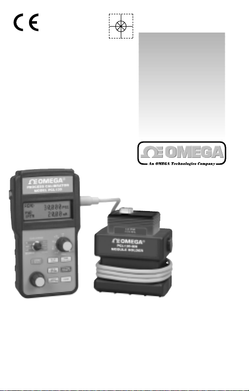
PCL-130
Process Calibrator
Page 2

CONTENTS
GENERAL OPERATING INSTRUCTIONS ...........................3
TURN ON ...................................................................5
CONNECTIONS .........................................................5
FIELD & BENCH USE (TILT STAND).........................6
CHANGING BATTERIES............................................6
CONFIGURING TEMPERATURE SCALES ...............7
ENABLING AUTO-OFF...............................................7
RESTORING DEFAULT SETTINGS...........................7
DISPLAY CONTRAST & BACKLIGHTING.................8
SELECTING FUNCTIONS & RANGES......................9
SOURCE MODE OPERATING INSTRUCTIONS...............10
STORING & RECALLING QUIK-CHEK®OUTPUTS10
SOURCE MODE CONNECTION INSTRUCTIONS
CALIBRATE MILLIAMP INPUTS ..............................11
SIMULATE 2-WIRE TRANSMITTERS......................12
CALIBRATE VOLTAGE INPUTS...............................13
CHECK 1-5 VOLT INPUTS WITHOUT
DISCONNECTING WIRES.......................................14
CALIBRATE THERMOCOUPLE INPUTS.................16
CALIBRATE RESISTANCE INPUTS........................17
CALIBRATE RTD INPUTS........................................18
CALIBRATE FREQUENCY INPUTS ........................20
READ MODE OPERATING INSTRUCTIONS ....................21
MIN/MAX ..................................................................21
OUT OF RANGE SIGNALS......................................21
READ MODE CONNECTION INSTRUCTIONS
READ MILLIAMP OUTPUTS....................................22
READ VOLTAGE OUTPUTS.....................................23
READ AC VOLTAGES...............................................24
MEASURE THERMOCOUPLE SENSORS..............25
READ RESISTANCE ................................................26
CHECK CONTINUITY..............................................27
MEASURE RTD SENSORS .....................................28
COUNT FREQUENCIES..........................................30
CALIBRATE 2 & 4 WIRE TRANSMITTERS .............32
PRESSURE (WITH COMPANION PRESSURE MODULES)
READ PRESSURE...................................................34
CALIBRATE PRESSURE TRANSMITTERS.............36
SPECIFICATIONS...............................................................40
WARRANTY........................................................................48
3
Your New PCL-130
Lighten your load…take the PCL-130 to ever y site. It’s
like bringing a cartload of test equipment from the shop to
the control room or the field. The PCL-130 sources and
reads DC like a milliamp or voltage calibrator, simulates and
measures T/Cs & R TDs lik e a temperature calibr ator, generates and counts frequency and Counts-Per-Minute like a
frequency calibrator and displays pressure like a precision
test gauge. Troubleshooting? It checks continuity with a
beeper and measures AC line voltage like a multimeter!
Calibrate Milliamp Inputs
Calibrate controllers, recorders and other devices in 4
to 20 or 0 to 20 mA loops. Source and read 0.00 to 24.00
mA, or Simulate a 2-Wire Transmitter.Use the optional AC
adaptor for continuous operation.Display to 0.01 mA , 0.1
% of 4 to 20 and 0.1 % DP Flow.
Calibrate 2-Wire Transmitters
Easily calibrate 2-Wire Pressure and Electronic
Transmitters by connecting the PCL-130 to both the input
and output of the transmitter. The PCL-130 will simultaneously indicate the input and output of the transmitter on the
graphical display.
Calibrate Pressure Systems
Read pressure with extreme accuracy using an external
PM130 pressure module in a companion PCL130-MH
module holder. Attach the module directly to the pressure
connection for the best accuracy or with optional tubing for
tight spots. Display to five digits within 0.025% of reading
in up to 20 engineering units including psi, pa, Kpa, Mpa,
BAR, mBar, Atm, Kgf plus torr, inches and mm of mercury
GENERAL INFORMATION
Page 3
54
or water at a variety of temperatures. Each module is fully
characterized for temperature and linearity to give you laboratory accuracy in the shop, control room or field.
Voltage Calibration
Calibrate all your DC millivolt and voltage instrumentation. Source from 0.00 to 110.00 mV and 0.00 to 10.25 V.
Read up to 110.00 mV, 11.00 V and 200.0 VDC.
Temperature Calibration
Source and Read directly in °C and °F for T/C types J,
K, T, E, R, S & N and four Pt 100 Ohm, Ni 120 Ohm and Cu
10 Ohm RTDs. Resolution to 0.1°. Cold junction compensation continuously tracks ambient temperature changes.
Frequency Calibration
Generate zero crossing square waves from 1 to 1000 Hz,
0.01 to 10.00 kHz and from 1 to 1000 CPM (Counts-PerMinute).Built-in frequency counter measures Hz, kHz & CPM.
Measure AC Voltage
Check line voltage or mains from 0.0 to 250.0 volts AC.
Great for troubleshooting power problems.
Check Continuity
Locate pairs of wires, open connections and shorts with
the built-in beeper.
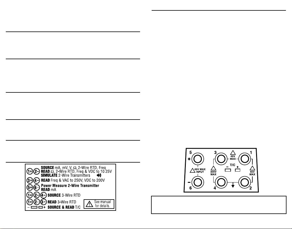
Rear Label - Condensed Operation Guide
GENERAL
TURN-ON
Each time you turn on the PCL-130 it runs through a self check
then returns to the most recently selected settings.
SOURCE - The three QUIK-CHEK outputs will be the same as
previously stored. Each time a different function is selected, the
associated three QUIK-CHEK outputs will be recalled.
READ - The 130 is ready to measure the same signal as the last
time it was used and automatically updates the MAX & MIN
readings for recall at any time.
CONNECTIONS
PCL-130 has protected banana jacks compatible with standard
and safety banana plugs.
Included with your TechChek are: a pair of safety test leads with
test probes, safety alligator clips, standard alligator clips and
spade lugs for attachment to a wide variety of instruments. An
additional test lead and spade lug are also included for 3-Wire RTD
connections.
A second pair of test leads with right angled safety banana plugs
and alligator clips for mA Read and Power Transmitter functions.
Thermocouple connections are made through a miniature thermocouple socket.
CAUTION! To prevent accidently overloading the instrument
being tested, correctly set up the outputs before connecting
the PCL-130 to any instruments to be calibrated.
!
!
!
!
Page 4
6
7
GENERAL
CONFIGURING TEMPERA TURE SCALES
The thermocouple and RTD ranges may be configured for full time
use of °C, full time use of °F or selectable °C and °F operation.
This configuration is part of the DEFAULT SETTINGS below.
AUTO-OFF
PCL-130 can be set up to turn itself off after 30 minutes of inactivity. The inter nal timer is reset to 30 minutes each time the digital
pot is turned or a pushbutton is pressed.
DEFAULT SETTINGS
PCL-130 may be restored to the factory default setting. This will
reset the HI and LO “QUIK-CHEK”memories according to the tab le
below and the SET memory to midrange between HI and LO.
OPERATING INSTRUCTIONS
1) Press and hold the STORE/RESET push-button while turning
the 130 on.
2) Keep pressing the push-button until SETTING UP DEFAULT
appears on the display then release the push-button.
3) °F/°C SETUP appears on the display.
4) Turn the digital pot to select °F & °C, °F Only or °C Only. °C &
°F is the default if no selection is made.
5) Press STORE/RESET push-button to store your choice or wait
five seconds for the 130 to automatically store your choice and
AUTO-OFF SETUP appears on the display.
6) Turn the digital pot to select AUTO-OFF ENABLE. AUTO-OFF
causes the 130 to turn itself off after 30 minutes of inactivity to
preserve the batteries. Select AUTO-OFF DISABLE for continuous operation.
7) Press STORE/RESET push-button
to store your choice or wait five
seconds for the 130 to automatically store your choice.
8) The firmware revision will be
displayed, then the 130 will begin
operation with the new settings.
OPERATING INSTRUCTIONS
GENERAL
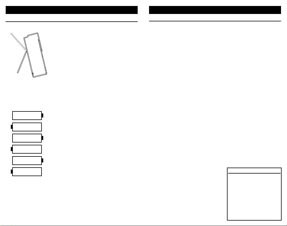
FIELD & BENCH USE
PCL-130 comes with a carrying case and a
built-in tilt stand/hanger. The 130 is held
securely in the case by VELCRO® for use
with the carrying case open. The carrying
case also has a snap-on belt loop which
can be looped around a pipe or rail.
The tilt stand is easily raised by pulling the
stand until it locks into place.The stand can
also be reversed for use as a hanger to
suspend the 130.
CHANGING BATTERIES
Low battery is indicated by a battery
symbol on the display. Approximately four
hours of operation remain before the LCD
blanks and PCL-130 shuts itself down. Turn
the 130 off, loosen the captive screw
securing the battery compartment and lift
off the cover from the bottom of the case.
The six “AA” batteries are easily removed
and replaced (alkaline supplied and recommended).Replace the battery compartment
cover by inserting the tabs and tightening
the screw.
QUIK-CHEK DEFAULTS
RANGE LO SET HI
mA 4.00 12.00 20.00
mV 1.00 5.00 10.00
V 1.00 5.00 10.00
T/C J,T,E,K,N All points 0°C/32°F
T/C R & S All points 538°C/1000°F
Ohms 100.0 200.0 400.0
RTD All points 0°C/32°F
kHz 1.00 5.00 10.00
Hz 100 5001000
CPM 100 500 1000
Page 5
GENERAL
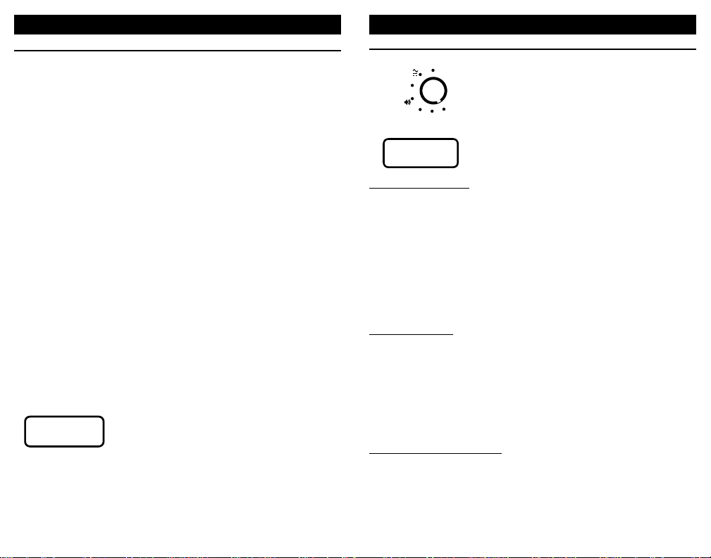
SELECTING FUNCTIONS
Turn the selector knob to choose among
mA, V, T/C, Ω, RTD, FREQ and
PRESSURE.
SELECTING RANGES
Press the RANGE/TYPE pushbutton to
select the desired range and scale.
SOURCE RANGES
Milliamp:
Source: mA, %mA (% 4-20), DP% (% Differential Pressure)
2-Wire Simulator: mA, %mA (% 4-20), DP% (% Differential
Pressure)
VDC: mV, V
T/C:Types J, T, E, K, N, R & S in °C &°F
Ohms: Ohms
RTD:Four Pt 100Ω, Ni 120Ω & Cu 10Ω in °C &°F
Frequency:KHz, Hz, CPM
READ RANGES
Milliamp: mA, %mA (% 4-20), DP% (% Differential Pressure)
VDC: mV, 10V, 200V
T/C:Types J, T, E, K, N, R & S in °C &°F
Ohms: Ohms
RTD:Four Pt 100Ω, Ni 120Ω & Cu 10Ω in °C &°F
Frequency:KHz, Hz, CPM
AC V olts:V A C
TRANSMITTER RANGES
Pwr Xmtr: Supplies nominal 24 VDC to power the transmitter while
measuring the transmitter milliamp signal . Can be simultaneously displayed with any Source Range or Pressure
Measurement
Read mA:Measures transmitter output
98
OPERATING INSTRUCTIONS
GENERAL
DISPLAY CONTRAST
The contrast of the Liquid Crystal Display may be adjusted for best
readability.
1) Press and hold the DISPLAY/SOURCE/READ push-button
while turning the 130 on to adjust the contrast of the display.
2) Turn the digital pot (knob) until the display is most legible.
3) Press the STORE/RESET push-button or wait five seconds for
your selection to be stored.
DISPLAY BACKLIGHTING
The LCD may have too little contrast where the lighting is dim or
the 130 is in shadow.Turn on the LCD backlighting to make the
display easy to read.
1) If the PCL-130 is off, turn it on and wait for the display to come
up in normal mode.
2) Press and hold the DISPLAY/SOURCE/READ push-button for
three seconds and the backlight will turn on.
To extend the life of the batteries, it is recommended that the
backlighting be turned off when the LCD is in normal light. Press
and hold the DISPLAY/SOURCE/READ push-button for three
seconds and the backlight will turn off.
TURN OFF
Press the POWER push-button to turn the
130 off.If AUT O-OFF is enabled, the 130 will
turn itself off after 30 minutes of inactivity.
OPERATING INSTRUCTIONS
POWER
mA
V
T/C
Ω
RTD
FREQ
PRESSURE
TYPE
ENG UNITS
Page 6
11
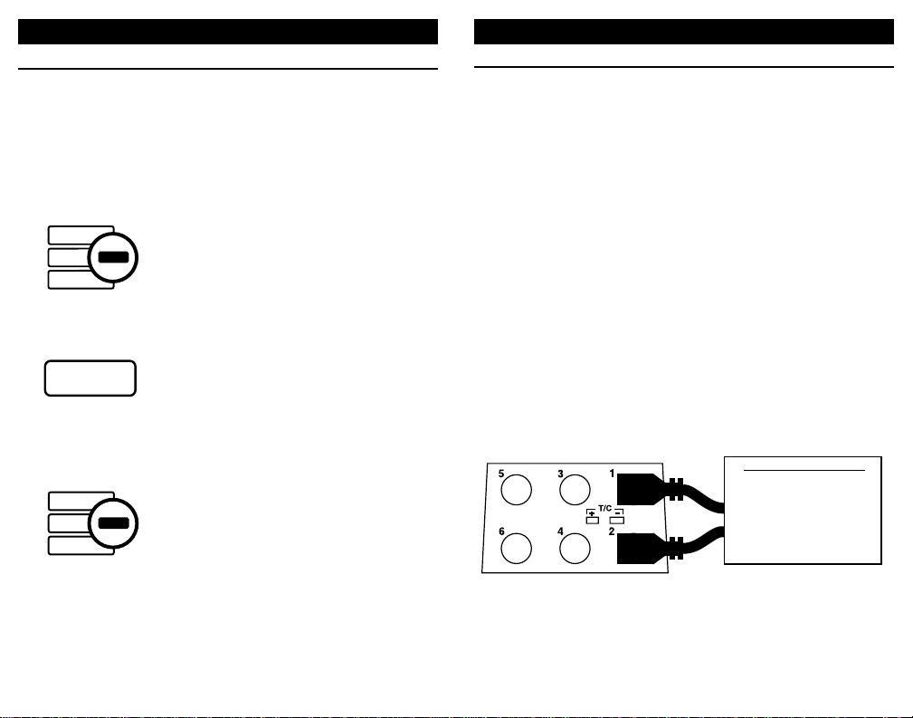
CALIBRATE MILLIAMP INPUTS
mA, mA % (Percent of 4 to 20 mA), DP% (DP Flow)
Choose this function to provide an output from 0.00 to 24.00
milliamps.The compliance voltage is a nominal 24 VDC to pro vide
the driving power to your milliamp receivers.
1) Disconnect one or both input wires from the device to be
calibrated.
2) Turn the Selector Knob to mA
3) Press the DISPLAY/SOURCE/READ push-button until SOURCE
or 2-WIRE appear on the display
4) If 2-WIRE is on the display, press the TYPE/ENG UNITS pushbutton once to indicate SOURCE on the display
5) Press the mA/%/% DP FLO W push-b utton to display mA, % 4-20
or % DP Flow.
6) Connect the red SOURCE lead of the calibrator to the plus (+)
input of the device and the black SOURCE lead to the minus (-).
Output current is continuously adjustable with the "QUIK-CHEK"
switch in the SET position. Zero & Span (or any other values) are
available by using the LO and HI "QUIK-CHEKs".
OPERATING INSTRUCTIONS
SOURCE MODE
Select source by pressing the DISPLAY/SOURCE/READ
pushbutton until the word SOURCE appears on the LCD display.
To change the output value, turn the speed sensitive digital pot.
Turning the knob slowly will cause a g radual change in the output.
A faster rate of change will occur when the knob is turned faster.
This function operates in all three output positions (HI, SET & LO).
STORING QUIK-CHEK OUTPUTS
1) Switch to HI or LO
2) Turn the knob to desired value
3) Press the STORE push-button
The LCD will flash once to show that the
value was saved
If a value is in the SET position and you
want that value stored in HI or LO, press
and hold the STORE push-button while
moving the switch to HI or LO. The display
will flash once to indicate the value has
been stored. Then release the STORE
push-button.
RECALLING QUIK-CHEK OUTPUTS
When you need a stored value just flip the
QUIK-CHEK switch. Any value for the
selected range may be stored in HI & LO.
The PCL-130 remembers the HI, LO and
SET values for each function with the
power on or off. Each time a different
function is selected, the last three QUIKCHEK values for that function will be
recalled.
OPERATING INSTRUCTIONS
10
HI
SET
LO
SOURCE
STORE
RESET
HI
SET
LO
SOURCE
RED
BLACK
Milliamp Receiver Input
Controller
Transmitter
Computer
Logger
I/P
DCS
Page 7
13
CALIBRA TE V OL TAGE INPUTS
V, mV
Choose this function to provide an output from 0.00 mV to 110.00
mV and from 0.00 to 10.25 VDC.Current compliance up to 20 mA
to provide the driving power to your voltage receivers.
1) Disconnect one or both input wires from the device to be
calibrated
2) Turn the Selector Knob to V
3) Press the DISPLAY/SOURCE/READ push-button until SOURCE
and V or mV appear on the display
4) Press the TYPE/ENG UNITS push-button once to switch
between V and mV on the display
5) Connect the red SOURCE lead of the calibrator to the plus (+)
input of the device and the black SOURCE lead to the minus (-).
Output voltage is continuously adjustable with the "QUIK-CHEK"
switch in the SET position. Zero & Span (or any other values) are
available by using the LO and HI "QUIK-CHEKs".
OPERATING INSTRUCTIONS
12
OPERATING INSTRUCTIONS
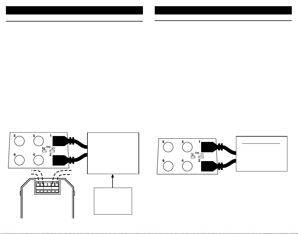
SIMULATE 2-WIRE TRANSMITTERS
2-WIRE mA, 2-WIRE % (Percent of 4 to 20 mA) 2-WIRE DP %
Choose this function to simulate a 2-Wire Transmitter output from
1.00 to 24.00 milliamps. Operates in loops with power supply
voltages from 3 to 45 VDC.
1) Disconnect existing 2-Wire Transmitter from the loop
2) Turn the Selector Knob to mA
3) Press the DISPLAY/SOURCE/READ push-button until SOURCE
or 2-WIRE appear on the display
4) If SOURCE is on the display, press the TYPE/ENG UNITS pushbutton once to indicate 2-WIRE on the display
5) Press the mA/%/% DP FLO W push-b utton to display mA, % 4-20
or % DP Flow.
6) Connect the red SOURCE lead of the calibrator to the plus (+)
input of the device and the black SOURCE lead to the minus (-).
The simulated output of the 2-Wire Transmitter is continuously
adjustable from 1.00 to 24.00 mA with the "QUIK-CHEK" switch in
the SET position. Zero & Span (or any other values) are available
by using the LO and HI "QUIK-CHEKs".
+IN-
REF +OUT-
Power Supply
2 to 45 VDC
Receiver
(Powers external
2-Wire Transmitter)
To
Sensor
Typical
2-Wire
Transmitter
(Disconnected)
RED
BLACK
Voltage Receiver Input
RED
BLACK
Controller
Transmitter
Computer
Logger
DCS
Page 8
1514
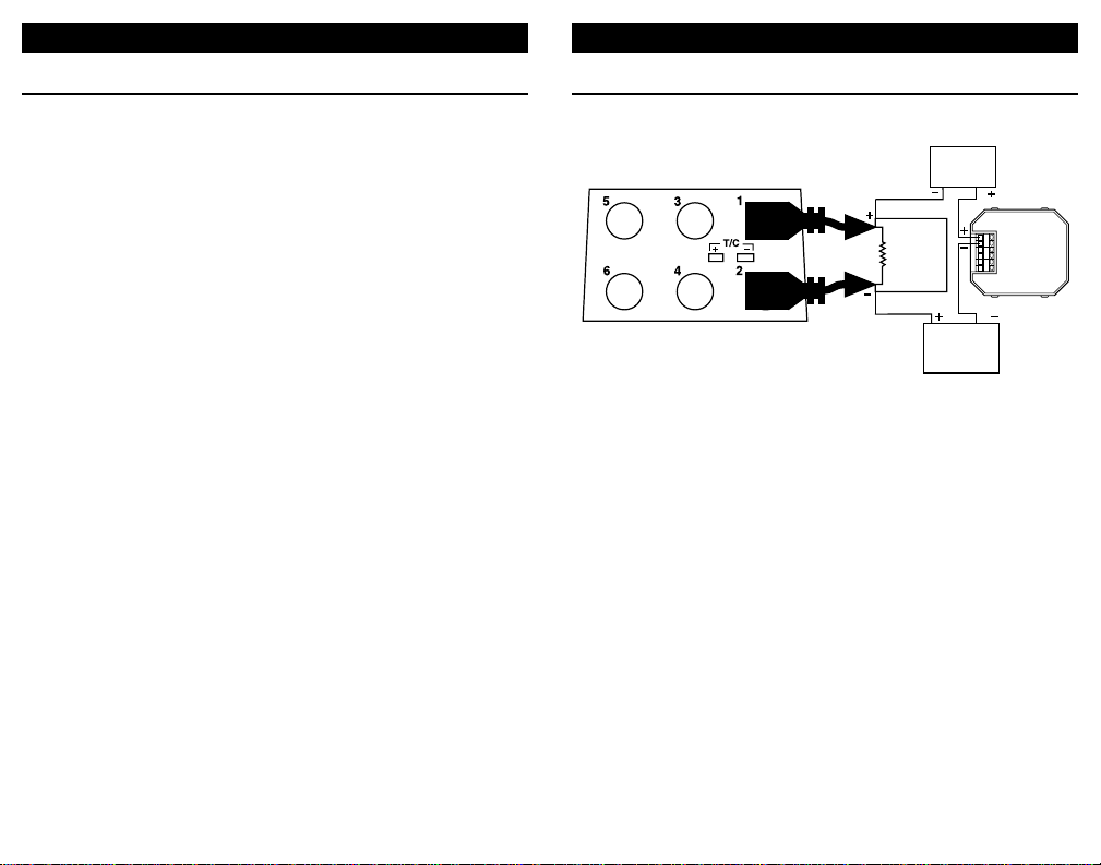
CHECK 1-5 VOLT INPUTS
WITHOUT DISCONNECTING WIRES
Most 1-5 Volt receivers in 4-20mA loops have a 250 Ohm resis-
tor across the input of the receiver.This resistor may be mounted
internally or externally. PCL-130 is connected directly across the
input of the 1-5 Volt receiver without disconnecting any field wiring.
This saves a great deal of time when a large number of voltage
receivers, such as chart recorders or computer systems, require
calibration.
Make certain that changing the signal input will not disturb the
process or cause unexpected alarms when checking on-line
instruments. It is impor tant to remember the 130 drives only the
device to which it is connected. It has no effect on other devices in
the 4 to 20 mA loop.PCL-130 will clamp the selected value in the
mV and V Ranges to the maximum source or sink current of >16
mA.
1) Turn the Selector Knob to V
2) Press the DISPLAY/SOURCE/READ push-button until SOURCE
and V or mV appear on the display
3) Press the TYPE/ENG UNITS push-button once to switch
between V and mV on the display
4) Connect the red SOURCE lead of the calibrator to the plus (+)
input of the device and the black SOURCE lead to the minus (-).
Any associated 250 Ohm resistor must not be disconnected.
OPERATING INSTRUCTIONS
CHECK 1-5 VOLT INPUTS
WITHOUT DISCONNECTING WIRES
OPERATING INSTRUCTIONS
CONTROLLER
(TYPICAL)
RED
BLACK
250Ω
RECORDER
COMPUTER
LOGGER
ETC,
1-5V DC
ADDITIONAL
4-20 mA OR 1-5V
INSTRUMENTS
Typical
2-Wire
REF +OUT-
Transmitter
+IN-
Page 9
1716
CALIBRATE RESISTANCE INPUTS
Choose this function to simulate a resistance into a variety of
instruments.
1) Disconnect one or both input wires from the device to be
calibrated
2) Turn the Selector Knob to Ω
3) Press the DISPLAY/SOURCE/READ push-button until SOURCE
appears on the display
4) Connect the red SOURCE lead of the calibrator to the plus (+)
input of the device and the black SOURCE lead to the minus (-).
OPERATING INSTRUCTIONS
CALIBRA TE THERMOCOUPLE INPUTS
Choose this function to simulate a thermocouple signal into any
instrument requiring a thermocouple input. The output of the 130
is automatically cold junction compensated.
1) Disconnect the thermocouple from the instrument being
calibrated.
2) Turn the Selector Knob to T/C
3) Press the DISPLAY/SOURCE/READ push-button until SOURCE
and any T/C TYPE appear on the display
4) Use the proper thermocouple wire and corresponding miniature
T/C connector to connect PCL-130 to the thermocouple.
Output temperature is continuously adjustable with the "QUIKCHEK" switch in the SET position. Zero & Span (or any other
values) are available by using the LO and HI "QUIK-CHEKs
To Change the Thermocouple type
1) Press the TYPE/ENG UNITS push-button.The words SELECT
T/C TYPE and the current selection appear on the display.
until the desired T/C type and temperature scale appear.
2) Turn the digital pot (knob) until the required type appears on
the display.
3) Press the STORE/RESET push-button or wait 5 seconds to
store the selection
OPERATING INSTRUCTIONS
-
+
Instrument with
Thermocouple Input
Controller
Temperature Indicator
Temperature Trip or Alarm
Temperature T ransmitter
RED
BLACK
Receiver Input
Ohms or 2-Wire RTD
Controller
Transmitter
Computer
Page 10

1918
OPERATING INSTRUCTIONS
Three Wire RTD Connection
Two Wire RTD Connection
CALIBRATE RTD INPUTS
Four Wire RTD Connection
CALIBRATE RTD INPUTS
Choose this function to simulate a temperature signal into any
instrument requiring an RTD input.
1) Disconnect the RTD from the instrument being calibrated.
2) Turn the Selector Knob to RTD
3) Press the DISPLAY/SOURCE/READ push-button until SOURCE
and any RTD TYPE appear on the display
4) Connect using 2 or 3 wires as in the diagrams on the opposite
page. Spade lugs are recommended to minimize any contact
resistance.
Output temperature is continuously adjustable with the "QUIKCHEK" switch in the SET position. Zero & Span (or any other
values) are available by using the LO and HI "QUIK-CHEKs
To Change the RTD type
1) Press the TYPE/ENG UNITS push-button.The words SELECT
RTD TYPE and the current selection appear on the display.
2) Turn the digital pot (knob) until the required type appears on
the display.
3) Press the STORE/RESET push-button or wait 5 seconds to
store the selection
Note on 4-Wire Connections:
The PCL-130 may be used to calibrate instruments requiring a
4-Wire RTD connection.This connection is valid only when the
lead wires included with the 130 are used to connect the 130
directly to the instrument. Use of longer wires can cause errors
in the output setting.
For long 4-Wire cable runs use the 3-Wire connection and add
a stacking banana jack (not available from Altek) to connect a
second wire to jack #1. Connect this extra wire to the fourth
wire field connection.
OPERATING INSTRUCTIONS
RED
BLACK
Receiver Input
Ohms or 2-Wire RTD
Controller
Transmitter
Computer
RED
BLACK
BLACK
Jumper
RED
BLACK
Jumper
Instrument with
RTD Input
Controller
Temperature T ransmitter
Temperature Indicator
Temperature Trip or Alarm
+ COMP
SENSOR
}
- COMP
Page 11

2120
READ FUNCTIONS
Select read by pressing the DISPLAY/SOURCE/READ pushbutton until the word READ appears on the LCD display. The READ
functions measure the desired signal.Multiple scales are available
for some functions.
MIN/MAX
To read the Maximum or Minimum INPUT
since READ mode was entered, simply
switch to MAX or MIN.The value will appear
on the LCD along with the word MAX or
MIN.The MAX/MIN values are automatically updated and may be viewed at any time
without interrupting the other values.
RESTARTING MIN/MAX
Pressing the STORE/RESET push-button
will cause the 130 to store the present
reading into the MAX and MIN memories.
Upon releasing the STORE/RESET pushbutton the 130 will resume reading the input
and update the MAX & MIN values as the
measured signal changes.
OUT OF RANGE SIGNALS
Signals above or below those available for
the currently selected range will be indicated by OVER and UNDER on the display.
OPERATING INSTRUCTIONS
OVER
UNDER
CALIBRATE FREQUENCY INPUTS
Choose this function to provide pulses into frequency measuring
instruments. The 130 output is a zero crossing square wave from
-1V to +5V amplitude. Available ranges are from 0.01 to 10.00
kHz, 1 to 1000 Hz and from 1 to 1000 CPM (Counts-Per-Minute).
CPM is used to simulate extremely slow frequency signals with
greater resolution. For example, 10 Hz is equivalent to 600 CPM.
To convert from CPM to Hz Divide by 60. To convert from Hz to
CPM multiply by 60.
1) Disconnect one or both input wires from the device to be
calibrated
2) Turn the Selector Knob to FREQ
3) Press the DISPLAY/SOURCE/READ push-button until SOURCE
and KHz, Hz or CPM appear on the display
4) Press the TYPE/ENG UNITS pushbuuton to select between KHz,
Hz or CPM on the display
5) Connect the red SOURCE lead of the calibrator to the plus (+)
input of the device and the black SOURCE lead to the minus (-).
Output frequency is continuously adjustable with the "QUIKCHEK" switch in the SET position. Zero & Span (or any other
values) are available by using the LO and HI "QUIK-CHEKs"
OPERATING INSTRUCTIONS
MAX
READ
MIN
READ
STORE
RESET
RED
BLACK
Frequency Receiver Input
Flowmeter
Controller
Transmitter
Computer
Logger
DCS
Page 12

2322
READ DC and AC VOLTAGE OUTPUTS
mV, V, Vhi and Vac
Choose this function to measure from 0.00 to 110.00 millivolts (mV),
0.00 to 10.25 DC Volts (V). Use the high voltage connection to read
from 0.0 to 200.0 VDC (Vhi).See the next page for Volts AC.
1) Turn the Selector Knob to V
3) Press the DISPLAY/SOURCE/READ push-button until READ
appears on the display
4) Press the TYPE/ENG UNITS push-button to select mV, V, Vhi or
VAC on the display
5) Connect the red READ (+) lead and the black READ (-) lead of
the calibrator across the voltage to be measured.
Signals above or below those available for the currently selected
range will be indicated by OVER and UNDER on the display.
OPERATING INSTRUCTIONS
Connection for millivolts(mV) and Volts below 10.25 VDC (V)
Connection for DC Volts to 200.0 (vhi)
READ MILLIAMP OUTPUTS
mA, mA % (Percent of 4 to 20 mA), DP% (DP Flow)
Choose this function to measure from 0.00 to +24.00 milliamps.
1) Open the current loop at any convenient point along the signal
path
2) Turn the Selector Knob to mA
3) Press the DISPLAY/SOURCE/READ push-button until READ
appears on the display
4) Press the mA/%/% DP FLO W push-b utton to display mA, % 4-20
or % DP Flow.
5) Connect the red READ (+) lead of the calibrator to the more
positive point of the break and the black READ lead (-) to the
more negative
Display the present reading, Maximum or Minimum by moving the
toggle switch from READ to MAX or MIN.If PCL-130 is connected
in the wrong polarity , the word POL will flash on the displa y. Simply
reverse the leads for correct indication.
OPERATING INSTRUCTIONS
Milliamp Output Signal
Controller
Transmitter
P/I
DCS
RED
BLACK
DC Voltage
RED
BLACK
Output Signal
Controller
Transmitter
Power Supply
RED
BLACK
Voltage
Output Signal
Power Supply
Loop Voltage
Page 13

2524
MEASURE THERMOCOUPLE SENSORS
Choose this function to read a thermocouple. The input of the
PCL-130 is automatically cold junction compensated.
1) Disconnect the thermocouple from any instrument.
2) Turn the Selector Knob to T/C
3) Press the DISPLAY/SOURCE/READ push-button until READ
and any T/C TYPE appear on the display
4) Use the proper thermocouple wire and corresponding miniature
T/C connector to connect PCL-130 to the thermocouple.
To Change the Thermocouple type
1) Press the TYPE/ENG UNITS push-button.The words SELECT
T/C TYPE and the current selection appear on the display.
2) Turn the digital pot (knob) until the required type appears on
the display.
3) Press the STORE/RESET push-button or wait 5 seconds to
store the selection
OPERATING INSTRUCTIONS
+
-
READ AC VOLTAGES
Choose this function to measure from 0.0 to 250.0 V True RMS.
1) Turn the Selector Knob to V
3) Press the DISPLAY/SOURCE/READ push-button until READ
appears on the display
4) Press the TYPE/ENG UNITS pushbuuton to select VAC on the
display
5) Connect the red READ (+) lead and the black READ (-) lead of
the calibrator across the voltage to be measured.
Signals above or below those available for the currently selected
range will be indicated by OVER and UNDER on the display.
CAUTION:Care should be used when measuring AC voltage.The
included safety test probes or safety alligator clips should be
used. Do not exceed voltage limits shown on calibrator.
OPERATING INSTRUCTIONS
RED
BLACK
AC Voltage Signal
Mains
Line Voltage
Page 14
2726
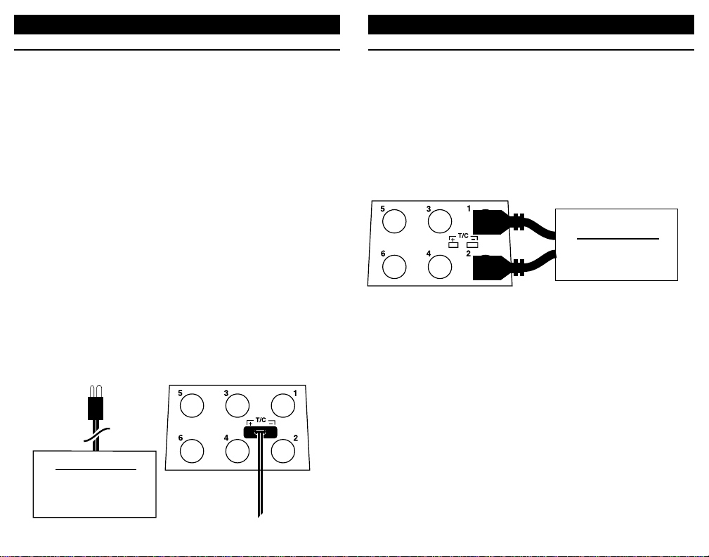
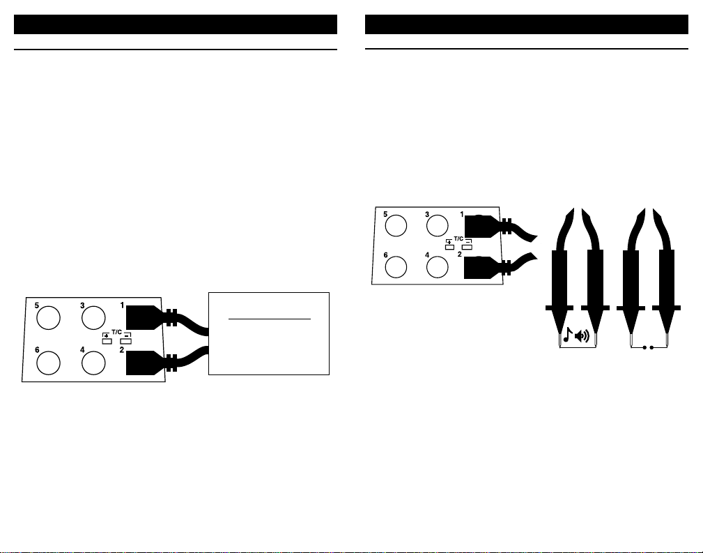
CHECK CONTINUITY
Choose this function to check continuity. A tone will sound and a
sound symbol will appear on the display when the resistance
between the leads is less than 100 Ohms.
1) Plug the leads into the PCL-130 as shown below.
2) Turn the Selector Knob to Ω
3) Press the DISPLAY/SOURCE/READ push-button until READ or
CONTINUITY appears on the display
4) Press the TYPE/ENG UNITS pushbutton once to switch between
READ and CONTINUITY on the display
OPERATING INSTRUCTIONS
READ RESISTANCE
Ohms
Choose this function to measure resistance from 0.0 to 1000.0
Ohms.
1) Disconnect one or both input wires from the device to be
calibrated
2) Turn the Selector Knob to Ω
3) Press the DISPLAY/SOURCE/READ push-button until READ or
CONTINUITY appears on the display
4) Press the TYPE/ENG UNITS push-button once to switch
between READ and CONTINUITY on the display
5) Connect the red READ (+) lead and the black READ (-) lead of
the calibrator across the resistance to be measured.
Signals above or below those available for the currently selected
range will be indicated by OVER and UNDER on the display.
OPERATING INSTRUCTIONS
Receiver Input
RED
BLACK
Ohms or 2-Wire RTD
Controller
Transmitter
Computer
RED
BLACK
Page 15

2928
OPERATING INSTRUCTIONS
MEASURE RTD SENSORS
MEASURE RTD SENSORS
Choose this function to read an RTD.Three wires must be use for
both 2 and 3 wire RTDs.
1) Disconnect the RTD from the instrument being calibrated.
2) Turn the Selector Knob to RTD
3) Press the DISPLAY/SOURCE/READ push-button until SOURCE
and any RTD TYPE appear on the display
4) Connect using 3 wires as in the diagrams on the opposite
page. Use a 3 wire connection to read a 4 wire RTD (all four
wires must be the same gauge). Spade lugs are recommended to minimize any contact resistance.
Output temperature is continuously adjustable with the "QUIKCHEK" switch in the SET position. Zero & Span (or any other
values) are available by using the LO and HI "QUIK-CHEKs
To Change the RTD type
1) Press the TYPE/ENG UNITS push-button.The words SELECT
RTD TYPE and the current selection appear on the display.
2) Turn the digital pot (knob) until the required type appears on
the display.
3) Press the STORE/RESET push-button or wait 5 seconds to
store the selection
OPERATING INSTRUCTIONS
RED
BLACK
BLACK
BLACK
BLACK
3
2
RTD Element
RED
1
Page 16

3130
Connection for signals with amplitudes below 10.25V RMS
Connection for signals with amplitudes to 250 V RMS
COUNT FREQUENCIES
OPERATING INSTRUCTIONS
COUNT FREQUENCIES
Choose this function to use the 130 as a frequecny counter.
Available ranges are from 0.01 to 10.00 kHz, 1 to 1000 Hz and
from 1 to 1000 CPM (Counts-Per-Minute).
To measure waveforms with amplitudes between 1 V and 10.25 V
RMS use the low level inputs. Use the high voltage connection to
read waveforms with amplitudes from 10.25 to 250.0 V RMS
1) Disconnect one or both input wires from the device to be
calibrated
2) Turn the Selector Knob to FREQ
3) Press the DISPLAY/SOURCE/READ push-button until READ
and KHz, Hz or CPM appear on the display
4) Press the TYPE/ENG UNITS push-b utton to select between KHz,
Hz or CPM on the display
5) Connect the red READ lead of the calibrator to the plus (+) input
of the device and the black READ lead to the minus (-)
OPERATING INSTRUCTIONS
Frequency Output Signal
RED
BLACK
RED
BLACK
Flowmeter
Flow Sensor
Variable Speed Drive
Controller
Transmitter
Frequency Output Signal
Flow Meter
Line Frequency
Variable Speed Drives
Page 17

33
32
OPERATING INSTRUCTIONS
CALIBRA TE TRANSMITTERS
ANY SOURCE FUNCTION AND
READ mA, READ %, READ DP%
Choose this function to supply the input signal to the transmitter
and displaying the 4-20 mA output of the transmitter (used with 4Wire Transmitters).
ANY SOURCE FUNCTION AND
P-XMTR mA, P-XMTR %, P-XMTR DP%
Choose this function to simultaneously supply power to a 2-Wire
transmitter while supply the input signal to the transmitter and
display the 4-20 mA output of the transmitter.
1) Disconnect both the input and output wires from the 2-Wire
Transmitter to be calibrated
2) Turn the selector knob to set the output of the 130 to match the
input of the transmitter (T/C, RTD, Freq, etc.).Select the proper
type, range and temperature scale if applicable.
3) Press the DISPLAY/SOURCE/READ push-button until READ
or P-XMTR appears in the lower half of the display
4) Press READ/POWER TRANSMITTER to switch between
reading milliamps and supply voltage to power the transmitter
5) Connect the output of the 130 to the signal input of the transmit-
ter (using the 1,2 & 4 connectors or the T/C connector on the 130)
6) Connect the red POWER lead of the 130 (Connector 5) to the
plus (+) output of the tranmitter and the black POWER lead
(Connector 6) to the minus (-)
The output is continuously adjustable with the "QUIK-CHEK"
switch in the SET position. Zero & Span (or any other values) are
available by using the LO and HI "QUIK-CHEKs".
The PCL-130 supplies a nominal 24 Volts DC at 24 mA to the 2Wire transmitter. The current output of the transmitter will be
accurately displayed by the 130. Calibrate the Transmitter in the
usual manner and disconnect the 130.
+IN-
REF
Typical
2-Wire
Transmitter
OPERATING INSTRUCTIONS
CALIBRATE 2-WIRE TRANSMITTERS
(T/C / mA Shown)
CALIBRATE 4-WIRE TRANSMITTERS
+IN-
REF
Typical
4-Wire
Transmitter
BLACK
RED
Loop
Power Supply
24 VDC
Page 18

3534
Pressure
Source
PROCESS CALIBRATOR
SOURCE READ
QUIK-CHEK®
HI
SET
LO
MIN
READ
MAX
TYPE
ENG UNITS
°C / °F
ZERO
DISPLAY
SOURCE READ
READ/POWER
TRANSMITTER
POWER
STORE
RESET
mA / %
% DP FLOW
Ω
RTD
T/C
V
mA
FREQ
PRESSURE
READ PRESSURE
Choose this function to measure pressure with a PCL130-MH
module holder and one of the many PM130 pressure modules.
1) Select the proper module for the pressure range of the process
2) Place the PM130 Module in the PCL130-MH holder
3) Plug the ModPak cable into the mating connector on the 130
4) Turn the selector knob to PRESSURE
5) The 130 will display – – – – – for up to 20 seconds while the
module is powered up and verified
6) The 130 will display the range of the module for three seconds
7) Press the °C/°F/ZERO push-button to “Zero” the pressure
reading
Carefully connect the module to the pressure point to be
measured.
To Change the pressure engineer ing units
1) Press the TYPE/ENG UNITS push-button.The words SELECT
ENG. UNITS and the current selection appear on the display.
2) Turn the digital pot (knob) until the required type appears on
the display.
3) Press the STORE/RESET push-button or wait 5 seconds to
store the selection
OPERATING INSTRUCTIONS
READ PRESSSURE
WARNING! - SAFETY CONSIDERATIONS
Sudden release of compressed or stored gas can cause personal
injury. Always vent the system before making pressure connections or disconnections. Exercise standard physical protection
practices such as eye protection, gloves, protective clothing, etc.
To prevent the potentially hazardous release into the atmosphere
of substances introduced into the pneumatic system by the user,
no relief valves are provided in the PM130 Pressure Module.
Consequently, if a module is overpressurized, the sensor will be
damaged.
FITTING INSTALLATION
All pneumatic connections to the PM130 Module are made via
1/8”-27 NPT threads in the pressure port. Adapter fittings may be
used for 1/4”-18, straight 10-32 threads or any other size fittings to
match the field connections.
To install a fitting in a module pressure por t:
1) Apply Teflon tape or pipe dope to the fitting threads (Teflon tape
not recommended with stainless steel fittings)
2) Carefully install the fitting in the pressure por t on top of the
module
3) Use a 5/8” wrench to support the pressure module port and a
second wrench to tighten the fitting
4) Check for leaks
OPERATING INSTRUCTIONS
Page 19

3736
OPERATING INSTRUCTIONS
CALIBRATE PRESSURE TRANSMITTERS
READ PRESSURE AND
P-XMTR mA, P-XMTR %, P-XMTR DP%
Choose this function to simultaneously supply power to a 2-Wire
pressure transmitter while supplying the input signal to the transmitter and displaying the 4-20 mA output of the transmitter.
1) Disconnect both the pressure input and output wires from the
2-Wire Transmitter to be calibrated
2) Select the proper module for the pressure range of the
process
3) Place the PM130 Module in the PCL130-MH holder
4) Plug the ModPak cable into the mating connector on the 130
5) Turn the selector knob to PRESSURE
6) The 130 will display – – – – – for up to 20 seconds while the
module is powered up and verified
7) The 130 will displa y the range of the module for three seconds
8) Press the °C/°F/ZERO push-button to “Zero” the pressure
reading
9) Press the DISPLAY/SOURCE/READ push-button until READ
or P-XMTR appears in the lower half of the display
10) Press READ/POWER TRANSMITTER to switch between
reading milliamps and supply voltage to power the transmitter
11) Carefully make all pressure connections
6) Connect the red POWER lead of the 130 (Connector 5) to the
plus (+) output of the transmitter and the black POWER lead
(Connector 6) to the minus (-)
Use the hand pump or regulated pressure source to adjust the
pressure
The PCL-130 supplies a nominal 24 Volts DC at 24 mA to the 2Wire transmitter. The current output of the transmitter will be
accurately displayed by the 130. Calibrate the Transmitter in the
usual manner and disconnect the 130.
PROCESS CALIBRATOR
QUIK-CHEK®
MAX
HI
READ
SET
MIN
LO
SOURCE READ
STORE
RESET
SOURCE READ
mA
V
T/C
Ω
RTD
PRESSURE
FREQ
TYPE
°C / °F
ENG UNITS
ZERO
mA / %
READ/POWER
TRANSMITTER
% DP FLOW
DISPLAY
POWER
Page 20

3938
OPERATING INSTRUCTIONS
CALIBRATE I/P (CURRENT TO PRESSURE) TRANSDUCERS
READ PRESSURE AND
mA, mA % (Percent of 4 to 20 mA), DP% (DP Flow) OR
2-WIRE mA, 2-WIRE % (Percent of 4 to 20 mA) 2-WIRE DP %
Choose this function to simultaneously supply the 4-20 mA control
signal to an I/P transducer while displaying the pressure output of
the transducer.
1) Shut off or disconnect the input pressure and disconnect both
the pressure output and input wires from the I/P to be calibrated
2) Select the module for the pressure range of the process
3) Place the PM130 Module in the PCL130-MH holder
4) Plug the ModPak cable into the mating connector on the 130
5) Turn the selector knob to mA and press TYPE to select mA
(using the internal supply) or 2-WIRE (to use an external
power supply)
6) Turn the selector knob to PRESSURE
7) The 130 will display – – – – – for up to 20 seconds while the
module is powered up and verified
8) The 130 will displa y the range of the module for three seconds
9) Press the °C/°F/ZERO push-button to “Zero”the pressure reading
10)Press the DISPLAY/SOURCE/READ push-button until
SOURCE or 2-WIRE appear in the upper half of the display
11) Carefully make all pressure connections
12) Connect the red POWER lead of the 130 (Connector 1) to the
plus (+) output of the transmitter and the black POWER lead
(Connector 2) to the minus (-)
Turn on or re connect a constant supply of pressure to the
pressure input of the I/P.
The output is continuously adjustable with the "QUIK-CHEK"
switch in the SET position. Zero & Span (or any other values) are
available by using the LO and HI "QUIK-CHEKs".
The pressure output of the I/P will be accurately displayed by the
130.Calibrate the I/P in the usual manner and disconnect the 130.
Pressure
Source
PROCESS CALIBRATOR
QUIK-CHEK®
HI
MAX
SET
READ
MIN
LO
SOURCE READ
STORE
RESET
% DP FLOW
SOURCE READ
mA
V
T/C
Ω
RTD
PRESSURE
FREQ
TYPE
°C / °F
ENG UNITS
ZERO
mA / %
READ/POWER
TRANSMITTER
DISPLAY
POWER
Page 21

41
40
SPECIFICATIONS
POWER & MEASURE 2-WIRE TRANSMITTERS
RANGES & ACCURACY: Same as for MILLIAMP SOURCE
OUTPUT CURRENT: up to 24.00 mA
TYPICAL DRIVE CAPABILITY:1200 Ohms @ 20.00 mA
COMPLIANCE VOLTA GE: nominal 25 VDC @ 20 mA
COMMON MODE ERROR: 0.01% Full Scale/Common Mode Volt
2-WIRE TRANSMITTER SIMULA T OR
RANGES:
1.00 to 24.00 mA; -18.8 to 125.0% of 4 to 20 mA; % DP Flow
ACCURACY: Same as for MILLIAMP SOURCE
LOOP VOLTA GE LIMITS: Mininum, 3 VDC;Maximum 45 VDC
OVERLOAD PROTECTION: Current limited to 25 mA nominal
COMMON MODE ERROR: 0.01% Full Scale/Common Mode Volt
MILLIAMP READ
RANGES:
0.00 to 24.00 mA; -25.0 to 125.0 % of 4 to 20 mA; % DP Flow
ACCURACY: Same as for MILLIAMP SOURCE
OVERLOAD PROTECTION:Current limited to 25 mA nominal
VOLTA GE BURDEN:0.9V at 4 mA, 1.2V at 20 mA, 1.9V at 24 mA
DC VOLTA GE SOURCE
RANGES: 0.00 to 110.00 mV;0.00 to 10.25V
ACCURACY:
±(0.05% of 110 mV+ 0.01mV) = ±0.07 mV
±(0.05% of 10.25 V + 0.01V) = ±0.02V
SOURCE CURRENT: >20 mA
SINK CURRENT: >20 mA
OUTPUT IMPEDANCE: <0.3 Ohms
SHORT CIRCUIT DURATION: Infinite
MEASURE AC VOLTS
RANGE: 0.0 to 250.0 V Tr ue RMS
ACCURACY: From 10 to 250 V A C ±(2% of 250 V + 0.1 VAC) = ±5.1 V A C
MAXIMUM CREST FACTOR: < 3
FREQUENCY RANGE: 45 to 800 Hz
SPECIFICATIONS
GENERAL
TYPICAL 90 DAY ACCURACY :±(0.025% of Full Scale + 1 LSD)
1
1 YEAR ACCURA CY: ±(0.05% of Full Scale + 1 LSD)
WARM UP TIME: 10 seconds to specified accuracy, 2 minutes to
maximum accuracy
TEMPERATURE EFFECT: ±0.01% per °C based on 23°±25°C
BATTERIES: Six “AA”, (R6) batteries (Alkaline supplied and
recommended)
BATTERY LIFE:
MILLIAMP SOURCE & 2-WIRE MODES: Nominal 12 hours at
20 mA with 250Ω load; OTHER FUNCTIONS: Nominal 30 hours
Note: Battery life is reduced when LCD backlighting is on
LOW BATTERY INDICATION: “BAT” indication on the display at
approximately 4 hours left
OVERLOAD PROTECTION:Two fuses - LITTLEFUSE R451.125
NOISE: ±1 LSD at frequencies less than 10 Hz
NORMAL MODE REJECTION RATIO: 50 dB @ 50/60 Hz
OPERA TING TEMPERA TURE RANGE:-5 to +130 °F (-20 to +55°C)
STORA GE TEMPERA TURE RANGE: -13 to +130°F (-25 to +55°C)
RELATIVE HUMIDITY: 10 to 90%, non-condensing for 24 hours
from 0 to 35°C
OVERALL SIZE: 158.1 x 83.1 x 49.3 mm (6.23 x 3.27 x 1.94”)
WEIGHT: 0.6 kg (1 lb, 5 oz)
MILLIAMP SOURCE
RANGES:
0.00 to 24.00 mA; -25.0 to 125.0 % of 4 to 20 mA; % DP Flow
ACCURACY: ±(0.05% of 24 mA Span + 0.01 mA) = 0.02mA
TYPICAL DRIVE CAPABILITY: 1200 Ohms @ 20.00 mA
COMPLIANCE VOLTA GE: nominal 25 V @ 20 mA
1
Typical 90 day accuracy can be estimated by dividing the 1 year
% of full scale accuracy by 2.Additions to the specification, such
as + 1 LSD, remain constant
Specifications subject to change without notice
Page 22

43
42
SPECIFICATIONS
SOURCE RTD & OHMS
RTD TYPES:
Pt 100Ω for 1.3850 (DIN/IEC 751 & New JIS), 1.3902 (Burns),
1.3926 (US Lab) & 1.3916 (Old JIS 1604C-1981)
Ni 120Ω and Cu 10Ω
RTD RESOLUTION: 1°C or 1°F
RANGE OHMS: 0.0 to 400.0 Ohms
ACCURACY: ±0.05% of Full Scale + 0.075 mV/mA Excitation Current
ACCURACY OHMS:±(0.05% of 400.0 Ohms + 0.1 Ohm = ±0.3 Ohms
(At 1 mA Excitation Current)
TEMPERA TURE EFFECT :±((0.035 mV/°C)*(1/mA Excitation Current))
ALLOW ABLE EXCITATION CURRENT :0.125 to 2.0 mA continuous DC
READ RTD
RTD TYPES & RESOLUTION: Same as for SOURCE RTD
RTD RANGE (IN OHMS): 0.0 to 400.0 Ohms
RTD ACCURA CY (OHMS):±(0.05% of 400.0 Ohms + 0.1 Ohm = ±0.3 Ohms
EXCITATION CURRENT SUPPLIED: 1 mA, nominal
FREQUENCY SOURCE
RANGES:1 to 1000 CPM (Count-P er-Minute);1 to 1000 Hz, 0.01 to 10.00 kHz
ACCURACY:
±(0.05% of 1000 CPM + 1 CPM) = ±2 CPM
±(0.05% of 1000 Hz + 1 Hz) = ±2 Hz
±(0.05% of 10.00 kHz + 0.01 kHz) = ±0.02 kHz
OUTPUT WA VEFORM: Square Wave, Zero Crossing, -1V to +5V ±10%
RISETIME: Hz <5 microseconds; CPM <100 microseconds
OUTPUT IMPEDANCE: <100 Ohms
SOURCE CURRENT: >1 mA at 10 kHz
SHORT CIRCUIT DURATION: Infinite
MEASURE FREQUENCY
RANGES & ACCURACY: Same as for FREQUENCY SOURCE
TRIGGER LEVEL: 1 V RMS, DC coupled to 10.25 V;
7 V RMS, DC coupled to 250 V
INPUT IMPEDANCE: > 1Meg Ohm + 60 pF
SPECIFICATIONS
MEASURE DC VOLTS
RANGES:
0.00 to 110.00 mV; 0.00 to 10.25 V; 0.0 to 200.0 V
ACCURACY:
±(0.05% of 110 mV+ 0.01mV) = ±0.07 mV
±(0.05% of 10.25 V + 0.01V) = ±0.02V
±(2% of 200.0 V + 0.1V) = ±4.1 V
INPUT RESIST ANCE:>1 Meg Ohm to 10.25V, >5 Meg Ohm to 200V
SOURCE RESISTANCE EFFECT: 0.01% per 100 Ohms
SOURCE THERMOCOUPLES
THERMOCOUPLE TYPES: J, K, T, E, N, R & S
RESOLUTION: 1°C or 1°F
ACCURACY :°C ±(0.05% OF 80 MV + 1°C);°F ±(0.05% OF 80 MV + 1°F)
COLD JUNCTION ACCURACY:±1°C
COLD JUNCTION EFFECT: within 0.05°C per °C change
OUTPUT IMPEDANCE: <0.3 Ohms
SOURCE CURRENT: >10 mA, Max
READ THERMOCOUPLES
THERMOCOUPLE TYPES & ACCURACY:Same as for SOURCE T/C
RESOLUTION: 0.1°C or 0.1°F
COLD JUNCTION ACCURACY:±1°C
COLD JUNCTION EFFECT: within 0.05°C per °C change
INPUT IMPEDANCE: > 1 Meg Ohm
OPEN THERMOCOUPLE DETECTION: 450 millisecond pulse.
Nominal threshold, 10 K Ohms.
READ OHMS
RANGE OHMS: 0.0 to 1000.0 Ohms
ACCURACY: ±(0.05% of 1000.0 Ohms + 0.1 Ohm) = ±0.6 Ohms
EXCITATION CURRENT SUPPLIED: 1 mA, nominal
CONTINUITY CHECKING
TEST CURRENT: Nominal 1 mA
THRESHOLD: 100 Ohm ±20%
INDICATION: Steady tone & Symbol on LCD plus Ohm Reading
Page 23

4544
THERMOCOUPLE SPECIFICATIONS THERMOCOUPLE SPECIFICATIONS
T/C
TYPE
J
K
T
E
°C °F
RANGE ACCURACY RANGE ACCURACY
100 to 1200 ±1.7 212 to 2192 ±2.3
-50 to 99 ±1.8 -58 to 211 ±2.5
-150 to -49 ±2.2 -238 to -57 ±3.2
-200 to -149 ±2.8 -328 to -237 ±4.3
1100 to 1372 ±2.2 2012 to 2500 ±3.1
0 to 1099 ±2.0 32 to 2011 ±2.9
-100 to -1 ±2.3 -148 to 31 ±3.3
-200 to -99 ±3.6 -328 to -147 ±5.7
200 to 400 ±1.7 392 to 752 ±2.4
0 to 199 ±1.9 32 to 391 ±2.7
-100 to -1 ±2.4 -148 to 31 ±3.5
-200 to -99 ±3.5 -328 to -147 ±5.6
250 to 1000 ±1.5 482 to 1832 ±2.0
50 to 249 ±1.6 122 to 481 ±2.1
-100 to 49 ±1.9 -148 to 121 ±2.6
-200 to -99 ±2.6 -328 to -147 ±3.9
T/C
TYPE
N
R
S
°C °F
RANGE ACCURACY RANGE ACCURACY
300 to 1300 ±2.1 572 to 2372 ±3.0
100 to 299 ±2.3 212 to 571 ±3.3
-50 to 99 ±2.6 -58 to 211 ±4.0
-200 to -49 ±5.0 -328 to -57 ±8.2
1750 to 1768 ±4.2 3182 to 3214 ±6.9
950 to 1749 ±4.0 1742 to 3181 ±6.5
650 to 949 ±4.4 1202 to 1741 ±7.2
300 to 649 ±5.1 572 to 1201 ±8.4
1700 to 1768 ±4.9 3092 to 3214 ±8.0
1050 to 1699 ±4.4 1922 to 3091 ±7.1
700 to 1049 ±4.8 1292 to 1921 ±7.8
300 to 699 ±5.4 572 to 1291 ±8.9
Note:Thermocouple accuracies are based on an 80.00 mV Span
T/C Accuracy for °C is ±(0.05% of 80.00 mV + 1°C)
T/C Accuracy for °F is ±(0.05% of 80.00 mV + 1°F)
Source resolution is 1 °C or °F. Read resolution is 0.1 °C or °F
Page 24

4746
RTD SPECIFICATIONS PM130 MODULE SPECIFICATIONS
RTD TYPE ALPHA °C RANGE ACCURACY
Pt 100Ω (DIN/IEC/JIS 1989) 1.3850 -100 to 850 ±1
Pt 100Ω (Burns) 1.3902 -100 to 648 ±1
Pt 100Ω (Old JIS 1981) 1.3916 -100 to 648 ±1
Pt 100Ω (US Lab) 1.3926 -100 to 862 ±1
Ni 120Ω 1.6720 -80 to 273 ±1
Cu 10Ω 1.4274 -200 to 260 ±8
RTD TYPE ALPHA °F RANGE ACCURACY
Pt 100Ω (DIN/IEC/JIS 1989) 1.3850 -148 to 1562 ±2
Pt 100Ω (Burns) 1.3902 -148 to 1200 ±2
Pt 100Ω (Old JIS 1981) 1.3916 -148 to 1200 ±2
Pt 100Ω (US Lab) 1.3926 -148 to 1584 ±2
Ni 120Ω 1.6720 -112 to 524 ±2
Cu 10Ω 1.4274 -328 to 500 ±1
RTD resolution is 1 °C or °F.
OPERA TING TEMPERA TURE: -10°C TO 50°C (13°F TO 122°F)
STORA GE TEMPERA TURE: -40°C TO 85°C (-40°F TO 185°F)
WEIGHT: 0.4 kg (14.5 oz)
TEMPERATURE EFFECT: None (Compensated over full range)
CONNECTION: 1/8” NPT FEMALE
MEDIA COMPATIBILITY: Any liquid or gas compatible with 316
stainless steel and fluorocarbon rubber
Modules
PM130-5 0 to 5 psi
PM130-10 0 to 10 psi
PM130-30 0 to 30 psi
PM130-100 0 to 100 psi
PM130-300 0 to 300 psi
PM130-500 0 to 500 psi
PM130-1000 0 to 1000 psi
PM130-2500 0 to 2500 psi
Module Accuracy
PM130-5 ±(0.025% of rdg +0.0005 psi)
PM130-10 ±(0.025% of rdg +0.001 psi)
PM130-30 ±(0.025% of rdg +0.003 psi)
PM130-100 ±(0.025% of rdg +0.009 psi)
PM130-300 ±(0.025% of rdg +0.027 psi)
PM130-500 ±(0.025% of rdg +0.035 psi)
PM130-1000 ±(0.025% of rdg +0.01 psi)
PM130-2500 ±(0.025% of rdg +0.25 psi)
Additional modules are frequently being
added to the PM130 line
Page 25

4948
OMEGA ENGINEERING, INC. warrants this unit to be free of defects in
materials and workmanship for a period of 37 months from date of
purchase. OMEGA Warranty adds an additional one (1) month grace
period to the normal three (3) years product warranty to cover
handling and shipping time. This ensures that OMEGA’s customers
receive maximum coverage on each product.
If the unit should malfunction, it must be returned to the factory for
evaluation. OMEGA’s Customer Service Department will issue an
Authorized Return (AR) number immediately upon phone or written
request. Upon examination by OMEGA, if the unit is found to be defective it will be repaired or replaced at no charge. OMEGA’s WARRANTY
does not apply to defects resulting from any action of the purchaser,
including but not limited to mishandling, improper interfacing, operation outside of design limits, improper repair, or unauthorized modification. This WARRANTY is VOID if the unit shows evidence of having
been tampered with or shows evidence of being damaged as a result
of excessive corrosion; or current, heat, moisture or vibration; improper specification; misapplication; misuse or other operating conditions
outside of OMEGA’s control. Components which wear are not warranted, including but not limited to contact points, fuses, and triacs.
OMEGA is pleased to offer suggestions on the use of its various
products. However, OMEGA neither assumes responsibility for
any omissions or errors nor assumes liability for any damages
that result from the use of its products in accordance with information provided by OMEGA, either verbal or written. OMEGA
warrants only that the parts manufactured by it will be as specified and free of defects.
OMEGA MAKES NO OTHER WARRANTIES OR REPRESENTATIONS
OF ANY KIND WHATSOEVER, EXPRESSED OR IMPLIED, EXCEPT
THAT OF TITLE, AND ALL IMPLIED WARRANTIES INCLUDING
ANY WARRANTY OF MERCHANTABILITY AND FITNESS FOR A
PARTICULAR PURPOSE ARE HEREBY DISCLAIMED.
LIMITATION OF LIABILITY: The remedies of purchaser set forth
herein are exclusive and the total liability of OMEGA with respect
to this order, whether based on contract, warranty, negligence,
indemnification, strict liability or otherwise, shall not exceed the
purchase price of the component upon which liability is based. In
no event shall OMEGA be liable for consequential, incidental or
special damages.
CONDITIONS: Equipment sold by OMEGA is not intended to be used,
nor shall it be used: (1) as a “Basic Component” under 10 CFR 21
(NRC), used in or with any nuclear installation or activity; or (2) in
medical applications or used on humans. Should any Product(s) be
used in or with any nuclear installation or activity, medical application,
used on humans, or misused in any way, OMEGAassumes no
responsibility as set forth in our basic WARRANTY/DISCLAIMER
language, and additionally, purchaser will indemnify OMEGA and hold
OMEGA harmless from any liability or damage whatsoever arising out
of the use of the Product(s) in such a manner.
Servicing North America:
USA: ISO 9001 Certified
One Omega Drive, Box 4047
Stamford, CT 06907-0047
Tel: (203) 359-1660 FAX: (203) 359-7700
e-mail: info@omega.com
Canada: 976 Bergar
Laval (Quebec) H7L 5A1
Tel: (514) 856-6928 FAX: (514) 856-6886
e-mail: canada@omega.com
For immediate technical or application assistance:
USA and Canada:
Sales Service: 1-800-826-6342 / 1-800-TC-OMEGASM
Customer Service: 1-800-622-2378 / 1-800-622-BESTSM
Engineering Service: 1-800-872-9436 / 1-800-USA-WHENSM
TELEX: 996404 EASYLINK: 62968934 CABLE: OMEGA
Mexico and Latin America:
Tel: (95) 800-TC-OMEGASM FAX: (95) 203-359-7807
En Espan˜ol: (203) 359-1660 ext: 2203
e-mail: espanol@omega.com
omega.com
OMEGAnetSMOn-Line Service Internet e-mail
http://www.omega.com info@omega.com
omega.com
TM
OMEGA
®
Page 26

It is the policy of OMEGA to comply with all worldwide safety
and EMC/EMI regulations that apply. OMEGA is constantly
pursuing certification of its products to the European New
Approach Directives.OMEGA will add the CE mark to every
appropriate device upon certification.
The information contained in this document is believed to be
correct but OMEGA Engineering, Inc. accepts
no liability for any errors it contains, and reserves the right to
alter specifications without notice.
WARNING:These products are not designed for use in, and
should not be used for, patient connected applications.
50
Servicing Europe:
Benelux:
Postbus 8034, 1180 LA Amstelveen, The Netherlands
Tel: (31) 20 6418405 FAX: (31) 20 6434643
Toll Free in Benelux: 06 0993344
e-mail: nl@omega.com
Czech Republic:
Ostravska 767, 733 01 Karvina
Tel: 420 (69) 6311627 FAX: 420 (69) 6311114
e-mail: czech@omega.com
France:
9, rue Denis Papin, 78190 Trappes
Tel: (33) 130-621-400 FAX: (33) 130-699-120
Toll Free in France: 0800-4-06342
e-mail: france@omega.com
Germany/Austria:
Daimlerstrasse 26, D-75392 Deckenpfronn, Germany
Tel: 49 (07056) 3017 FAX: 49 (07056) 8540
Toll Free in Germany: 0130 11 21 66
e-mail: germany@omega.com
United Kingdom: ISO 9002 Cer tified
25 Swannington Road, P.O.Box 7, Omega Drive,
Broughton Astley, Leicestershire, Irlam, Manchester,
LE9 6TU, England M44 5EX, England
Tel: 44 (1455) 285520 Tel: 44 (161) 777-6611
FAX:44 (1455) 283912FAX:44 (161) 777-6622
Toll Free in England: 0800-488-488
e-mail: uk@omega.com
Page 27

TEMPERATURE
Thermocouple, RTD & Thermistor
Probes, Connectors, Panels &
Assemblies
Wire: Thermocouple, RTD &
Thermistor
Calibrators & Ice Point References
Recorders, Controllers &
Process Monitors
Infrared Pyrometers
PRESSURE, STRAIN
AND FORCE
Transducers & Strain Gauges
Load Cells & Pressure Gauges
Displacement Transducers
Instrumentation & Accessories
FLOW/LEVEL
Rotameters, Gas Mass Flowmeters &
Flow Computers
Air Velocity Indicators
Turbine/Paddlewheel Systems
Totalizers & Batch Controllers
pH/CONDUCTIVITY
pH Electrodes, Testers & Accessories
Benchtop/Laboratory Meters
Controllers, Calibrators, Simulators
& Pumps
Industrial pH & Conductivity
Equipment
DATA ACQUISITION
Data Acquisition & Engineering Software
Communications-Based Acquisition
Systems
Plug-in Cards for Apple, IBM &
Compatibles
Datalogging Systems
Recorders, Printers & Plotters
HEATERS
Heating Cable
Cartridge & Strip Heaters
Immersion & Band Heaters
Flexible Heaters
Laboratory Heaters
ENVIRONMENTAL
MONITORING AND
CONTROL
Metering & Control Instrumentation
Refractometers
Pumps & Tubing
Air, Soil & Water Monitors
Industrial Water & Wastewater Treatment
pH, Conductivity & Dissolved Oxygen
Instruments
Where Do I Find Everything I Need for
Process Measurement and Control?
OMEGA…Of Course!
 Loading...