

Page 1

http://www.omega.com
@
r
e-mail: info
omega.com
PCL10 / PCL11
Hand-Held Pressure
Indicator-Calibrato
Page 2

OMEGAnetSM On-Line Service
Internet e-mail
http://www.omega.com
info@omega.com
Servicing North America:
USA:
ISO 9001 Certified
Canada:
One Omega Drive, Box 4047
Stamford, CT 06907-0047
Tel: (203) 359-1660
e-mail: info@omega.com
976 Bergar
Laval (Quebec) H7L 5A1
Tel: (514) 856-6928
e-mail: info@omega.ca
FAX: (203) 359-7700
FAX: (514) 856-6886
For immediate technical or application assistance:
Usa and Canada:
Mexico and
Latin America:
Sales Service: 1-800-826-6342 / 1-800-TC-OMEGA
Customer Service: 1-800-622-2378 / 1-800-622-BEST
Engineering Service: 1-800-872-9436 / 1-800-USA-WHEN
TELEX: 996404 EASYLINK: 62968934 CABLE: OMEGA
Tel: (95) 800-826-6342
En Español: (95) 203-359-7803
e-mail: espanol@omega.com
SM
SM
SM
FAX: (95) 203-359-7807
Servicing Europe:
Benelux:
Czech Republic:
France:
Germany/Austria:
United Kingdom:
ISO 9002 Certified
It is the policy of OMEGA to comply with all worldwide safety and EMC/EMI regulations that apply. OMEGA is constantly
pursuing certification of its products to the European New Approach Directives. OMEGA will add the CE mark to every
appropriate device upon certification.
The information contained in this document is believed to be corrected but OMEGA Engineering Inc. accepts no liability for any errors it
WARNING: These products are not designed for use in, and should not be used for, patient connected applications.
Postbus 8034, 1180 LA Amstelveen, The Netherlands
Tel: (31) 20 6418405
Toll Free in Benelux: 0800 0993344
e-mail: nl@omega.com
ul. Rude armady 1868, 733 01 Karvina-Hranice, Czech Republic
Tel: 420 (69) 6311899
Toll free: 0800-1-66342
e-mail: czech@omega.com
9, rue Denis Papin, 78190 Trappes
Tel: (33) 130-621-400
Toll Free in France: 0800-4-06342
e-mail: france@omega.com
Daimlerstrasse 26, D-75392 Deckenpfronn, Germany
Tel: 49 (07056) 3017
Toll Free in Germany: 0130 11 21 66
e-mail: info@omega.de
One Omega Drive , River Bend Technology Centre
Northbank, Irlam, Manchester
M44 5EX, England
Tel: 44 (161) 777-6611
Toll Free in United Kingdom: 0800-488-488
e-mail: info@omega.co.uk
contains, and reserves the right to alter specifications without notice.
FAX: (31) 20 6434643
FAX: 420 (69) 6311114
FAX: (33) 130-699-120
FAX: 49 (07056) 8540
FAX: 44 (161) 777-6622
2
Page 3

INTRODUCTORY NOTE
This publication contains operating instructions, as well as a description of the principles of operation, of
PCL10 and PCL11 pressure calibrators.
OMEGA has used the best care and efforts in preparing this book and believes the information in this
publication are accurate. The OMEGA products are subjected to continuous improvement, in order to pursue
the technological leadership; these improvements could require changes to the information of this book.
OMEGA reserves the right to change such information without notice.
No part of this document may be stored in a retrieval system, or transmitted in any form, electronic or
mechanical, without prior written permission of OMEGA Engineering Inc.
PCL10 and PCL11 units use sophisticated analogic and digital technologies. Any maintenance operation
must be carried out by qualified personnel
ONLY. We recommend to contact our technicians for any support
requirements.
.
PCL10 and PCL11 is fully tested in conformity with the directive n°89/336/CEE Electromagnetic
Compatibility. OMEGA shall not be liable in any event, technical and publishing error or omissions, for any
incidental and consequential damages, in connection with, or arising out of the use of this book.
3
Page 4

TABLE OF CONTENTS
1 PERFORMANCE.................................................................................................................................. 6
1.1 Specifications................................................................................................................................................... 7
1.1.1 Ranges and resolution ................................................................................................................................ 9
2 GENERAL FEATURES...................................................................................................................... 10
2.1 Input and output flexibility............................................................................................................................... 10
2.2 Self calibration................................................................................................................................................10
2.3 Keyboard........................................................................................................................................................ 10
2.4 Display ...........................................................................................................................................................10
2.5 Digital interface .............................................................................................................................................. 10
2.6 Scale factor function.......................................................................................................................................10
2.7 Square root function....................................................................................................................................... 10
2.8 Pressure measurement damping................................................................................................................... 10
2.9 Case............................................................................................................................................................... 10
3 PHYSICAL DESCRIPTION ................................................................................................................ 11
4 FUNCTIONAL DESCRIPTION........................................................................................................... 12
4.1 Power supply..................................................................................................................................................12
4.2 Operative keyboard........................................................................................................................................ 12
4.3 Pressure Module............................................................................................................................................ 13
4.4 Microcontroller................................................................................................................................................13
4.5 Firmware ........................................................................................................................................................ 13
4.6 Digital display................................................................................................................................................. 13
4.7 Battery charger...............................................................................................................................................13
4.8 Digital interface .............................................................................................................................................. 14
5 UNPACKING ...................................................................................................................................... 15
6 PRE-OPERATIONAL CHECK ........................................................................................................... 16
7 OPERATION & APPLICATIONS ....................................................................................................... 17
7.1 Rechargeable batteries..................................................................................................................................17
7.2 Battery charger...............................................................................................................................................17
7.3 How to maximize the life span of the battery.................................................................................................. 17
7.5 Start-up ..........................................................................................................................................................17
7.6 Instrument Configuration review (Status) ....................................................................................................... 18
7.7 Display contrast and backlight adjustment..................................................................................................... 19
7.8 Normal operative mode.................................................................................................................................. 19
7.9 Zero adjustment ............................................................................................................................................. 20
7.10 Pressure measurement damping ...................................................................................................................20
7.10.1 Averaged Value Calculation Algorythm ..................................................................................................... 21
7.11 Technical unit selection.................................................................................................................................. 22
7.12 Voltage and Current measurements ..............................................................................................................23
7.13 Peak & Valley measurement.......................................................................................................................... 23
7.14 Scale factor program...................................................................................................................................... 23
7.15 Alarm setting and operative mode..................................................................................................................25
7.16 Pressure switch test....................................................................................................................................... 26
7.17 Leak test.........................................................................................................................................................27
7.18 User’s Calibration........................................................................................................................................... 27
8 INSTRUMENT CONFIGURATION..................................................................................................... 29
9 CALPMAN APPLICATION PC SOFTWARE .................................................................................... 30
9.1 Introductory note ............................................................................................................................................ 30
9.2 Software Installation....................................................................................................................................... 30
9.3 General structure of the CalpMan software.................................................................................................... 30
9.4 Pressure gauges test ..................................................................................................................................... 33
9.5 Pressure transmitter test ................................................................................................................................33
9.6 Test result printout from PCL10/11 ................................................................................................................ 34
9.7 Test result printout from PC ........................................................................................................................... 35
10 DIGITAL INTERFACE........................................................................................................................ 36
10.1 Digital output wiring practice .......................................................................................................................... 36
10.2 TTL to RS 232 adapter...................................................................................................................................36
10.2.1 Communication protocol from PCL10/11 to a PC...................................................................................... 37
10.2.2 Computer request for PCL10/11 settings .................................................................................................. 38
4
Page 5

10.2.3 Communication programs ......................................................................................................................... 39
11 MAINTENANCE ................................................................................................................................. 41
11.1 General recommendations............................................................................................................................. 41
11.2 Safety recommendations ............................................................................................................................... 41
11.3 Protection fuses replacement.........................................................................................................................41
11.4 Faulty operating conditions ............................................................................................................................41
11.5 Storage .......................................................................................................................................................... 42
5
Page 6

1 PERFORMANCE
PCL10/11 is a portable instrument for relative (gauge) and differential pressure measurement.
When connected to an auxiliary device such as a pump, a volume adjuster and a ventilation valve it can be used as a
pressure calibrator.
A complete system testing, measuring and calibrating built in a single, compact portable instrument.
Thanks to its compactness, roughness and user friendly operative mode, PCL10/11 is the ideal instrument for field
measurements, tests and calibrations.
Accurate, compact, rugged, easy to use; the ideal solution to measure and simulate:
• Volts (only measurements)
• milliAmperes (only measurements)
• gauge pressure
• differential pressure
PCL10/11 has been developed using the most advanced microcontroller technique to provide high accuracy on
extended ranges and a powerful operating flexibility.
The calibration uses computerized procedures and the relevant calibration data are memory stored to ensure high
accuracy.
The pressure/differential pressure measurement uses a base piezoresistive sensor individually and fully characterized for
linearity and temperature coefficient.
In addition to pressure measurement the instrument is equipped with a second channel designed for voltage (up to 30 V)
and current (up to 22 mA) measurements.
The selection of operating functions is made on a polycarbonate thermoformed membrane keyboard which assures up to
one million operations per key.
Both pressure and electrical parameter readings are indicated on a high quality LCD dot matrix display equipped with a
backlight device for easy readings also in poor light conditions.
The case, made in shock-resistant ABS, is ergonomically designed for an easy practical use.
The instrument is powered by four Ni-MH rechargeable batteries; an external battery charger is supplied as a standard
accessory.
6
Page 7

1.1 Specifications
• Pressure and ∆P ranges:
see instrument codes
• Vacuum ranges:
-10% of the measuring range
(10 bar and 20 bar ranges only are limited to -0.8 bar)
• Keyboard selectable technical units:
mbar, bar, psi, mmwc (mmH
matm, atm, torr, Lbin
2
, kgm2, kgcm2
• Scale factor and square root:
for direct flow measurement
• Pressure media:
compatible with most common non-corrosive, non-reducing, non-condensing and non explosive gases
• Pressure ports:
1/8” BSPPF
• Accuracy:
Table A = 1 ±(0.1% of reading + 0.03% of f.s.)
Table A = 2 ±(0.05% of reading + 0.02% of f.s.)
The relative accuracy shown above are stated for 90 days and the operative conditions are from +5°C to +45°C.
Outside the above temperature band the temperature drift is ±0.004% rdg/°C
• Position effect:
negligible (excluded 20 mbar range)
• Electrical ranges:
0 to 30.000 V
0 to 22.000 mA
• Electrical ranges accuracy:
± (0.05% of reading + 0.01% of f.s.)
The relative accuracy shown above is stated for 90 days and the operative conditions are from +18°C to +28°C.
Outside the above temperature band the temperature drift is ±0.002% of rdg/°C
• Common mode rejection:
>140 dB at 50/60 Hz ± 1 Hz
• Normal mode rejection:
> 60 dB at 50/60 Hz ± 1 Hz
• Shunt (current channel):
< 110 Ω
• Impedance (voltage channel):
> 1 MΩ
• Maximum voltage input (voltage channel):
50V
• Maximum current input (current channel):
50 mA
• Short-circuit protection (loop power supply):
Fuse + Electronic
• Overcurrent protection (current channel):
Fuse
• Maximum load (passive loop):
900 Ω at 20 mA
• Display:
dot matrix LCD (2 lines of 16 characters each) with backlight device.
• Operative life:
8 hours without printing and without load on 20 mA passive current loop
4 hours without printing and with load on 20 mA passive current loop
O), cmwc (cmH2O), mwc (mH2O), inwc (inH2O), mmHg, mHg, inHg, kPa, hPa,
2
7
Page 8

• Data memory:
up to 50 group of data
• Working temperature limits:
from -5°C to 50°C
• Storing temperature:
from -20°C to 60°C
• Power supply:
Ni-MH batteries package
• Case:
Injection moulded ABS with internal metal coating in compliance with EMC
• External dimensions:
100 x 60 x 240 mm (without pressure module)
100 x 60 x 285 mm (with pressure module)
• Weights:
net 1 Kg (instrument + pressure module)
gross with packing 1,5 Kg
8
Page 9
1.1.1 Ranges and resolution
Bar
-0,880 22,000 -12,76 319,08 -8,97 224,34 -8,80 2200,0 -353 8832 -12,76 319,08
-0,880 11,000 -12,76 159,54 -8,97 112,17 -8,80 1100,0 -353 4416 -12,76 159,54
-0,550 5,500 -7,98 79,77 -5,61 56,08 -5,50 550,0 -220,8 2208,1 -7,98 79,77
-0,2200 2,2000 -3,191 31,908 -2,243 22,434 -2,200 220,00 -88,3 883,2 -3,191 31,908
Bar
-0,1100 1,1000 -1,595 15,954 -1,122 11,217 -1,100 110,00 -44,2 441,6 -1,595 15,954
mBar
-55,0 550,0 -0,798 7,977 -56,1 560,8 -5,50 55,00 -22,08 220,81 -0,798 7,977
mBar
-22,00 220,00 -0,3191 3,1908 -224,3 2243,4 -2,200 22,000 -8,83 88,32 -0,3191 3,1908
mBar
-11,00 110,00 -0,1595 1,5954 -112,2 1121,7 -11,00 110,00 -4,42 44,16 -0,1595 1,5954
mBar
-2,200 22,000 -31,91 319,08 -22,43 224,34 -2,200 22,000 -0,883 8,832 -0,0319 0,3191
PSI
PSI
PSI
PSI
PSI
mPSI
mH20 at 4°C kPa
mH20 at 4°C kPa
cmH20 at 4°C kPa
mmH20 at 4°C kPa
mmH20 at 4°C hPa
mmH20 at 4°C hPa
InH20 at 4°C Lb/In2
InH20 at 4°C Lb/In2
InH20 at 4°C Lb/In2
InH20 at 4°C Lb/In2
InH20 at 4°C Lb/In2
InH20 at 4°C Lb/In2
Bar
-0,880 22,000 -0,660 16,501 -660 16501 -0,897 22,434 -0,868 21,712 -25,99 649,7
-0,880 11,000 -0,660 8,251 -660 8251 -0,897 11,217 -0,868 10,856 -25,99 324,83
-0,550 5,500 -0,413 4,125 -413 4125 -0,561 5,608 -0,543 5,428 -16,24 162,42
-0,2200 2,2000 -0,1650 1,6501 -165,0 1650,1 -0,2243 2,2434 -0,2171 2,1712 -6,50 64,97
Bar
-0,1100 1,1000 -82,5 825,1 -82,5 825,1 -0,1122 1,1217 -0,1086 1,0856 -3,248 32,483
mBar
-55,0 550,0 -41,3 412,5 -41,3 412,5 -561 5608 -54,3 542,8 -1,624 16,242
mBar
-22,00 220,00 -16,50 165,01 -16,50 165,01 -224,3 2243,4 -21,71 217,12 -0,650 6,497
mBar
-11,00 110,00 -8,25 82,51 -8,25 82,51 -112,2 1121,7 -10,86 108,56 -0,3248 3,2483
-2,200 22,000 -1,650 16,501 -1,650 16,501 -22,43 224,34 -2,171 21,712 -0,0650 0,6497
mHg at 0°C torr
mmHg at 0°C torr
mmHg at 0°C torr
mmHg at 0°C torr
mmHg at 0°C torr
Kg/cm2
Kg/cm2
Kg/m2
Kg/m2
Kg/m2
Atm
Atm
mAtm
mAtm
mAtm
InHg at 0°C
InHg at 0°C
InHg at 0°C
InHg at 0°C
InHg at 0°C
9
Page 10

2 GENERAL FEATURES
2.1 Input and output flexibility
An advanced flexibility of performance has been achieved using the microcontroller technique. Each instrument, through
a menu-driven procedure, allows simultaneous measurement of pressure (gauge or ∆P) and of the typical loop signal in
current (up to 22 mA) or voltage (up to 30 V). The microcontroller performs linearization and temperature compensation
of the piezoresistive pressure sensor using the characterization data stored in the pressure module memory.
2.2 Self calibration
The hardware-firmware design allows the automatic calibration of the instrument. The calibration procedure is protected
by a security code.
2.3 Keyboard
A thermoformed metal-click tactile polycarbonate membrane keyboard, with a working life of one million operations per
key, seals the internal electronics from the surrounding environment. The contact closure of membrane keys is
acknowledged, as a coded signal, directly by the microprocessor.
2.4 Display
The high contrast alphanumeric LCD display with dot matrix (7x5 dots per character-16 characters ), in the normal
operative mode, simultaneously indicates pressure symbol and value, current or voltage symbol and value.
It is also used for operator’s messages, instrument configuration set-up, special operative modes, etc.
It is equipped with a backlight device to allow easy readings even in poor light conditions.
The method to adjust the display contrast is described in par. 8.7.
2.5 Digital interface
A digital interface with TTL logic levels is available as a standard for communication with external units. A serial data port
provides a communication capability at a logic level of 0-5 V (four wires: Tx, Rx, GND, Vcc). A TTL to RS 232 adapter is
available as an option.
2.6 Scale factor function
Easy menu-driven set-up to read or simulate electrical signal values in terms of engineering units. Four programmable
alphanumeric characters are available on the display to show the symbol of the parameter (i.e. mbar, etc.). The display
will indicate the scaled input value.
2.7 Square root function
It can be programmed during the set-up procedure to obtain direct readings of flow from a dP transmitter signal. The
display limits are -9999 and +30000.
2.8 Pressure measurement damping
To allow measurement of unstable input signals using a special algorithm based on a combination of working band and
average weight.
2.9 Case
The case is designed for an easy hand held operation and transportation. The body is injection molded, shock-resistant
ABS with internal metal coating. An ABS case for instrument + printer + pumps + accessories is available on request.
10
Page 11

3 PHYSICAL DESCRIPTION
The PCL10/11 palm-top indicator consists of a rugged and compact case, a replaceable pressure module, a mother
board with all basic functions, a daughter board for the auxiliary functions (mA and V readings), a tactile membrane
keyboard, a LCD display and a group of four nickel-metalhydride rechargeable batteries.
The internal surface of the case is metal coated to improve compliance with EMC.
The battery package is located on the lower back part of the case, and is accessible through a cover fastened by a
metal screw.
The two sections of the case are joined together by four metal screws located on the back side.
The optional leather case, with shoulder strap, assures a better protection of the instrument against mechanical knocks
or scratches.
11
Page 12
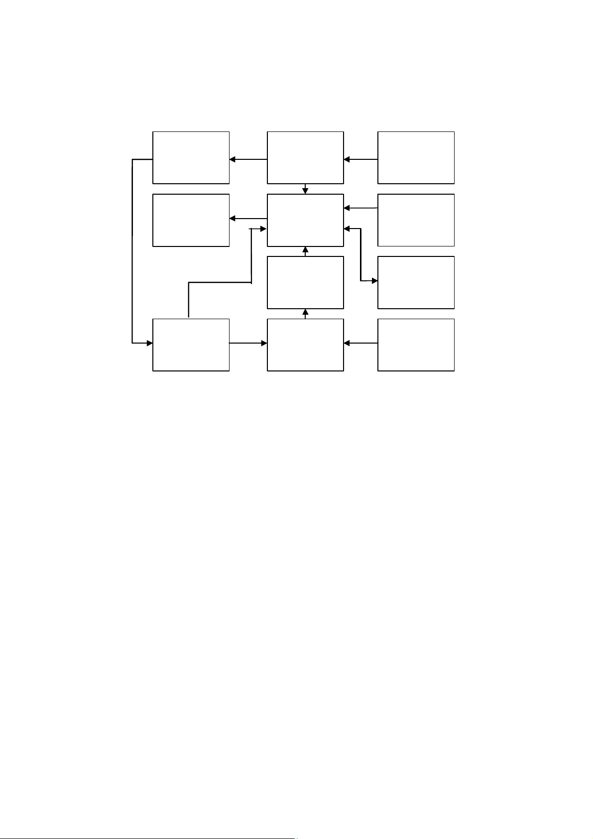
4 FUNCTIONAL DESCRIPTION
The PCL10/11 portable calibrator block diagram is shown below.
• power supply
• reference voltage signal
Reference
Voltage
Pressure sensor
Module + Memory
Power
Supply
Microcontroller LCD Display
Analog to Digital
Converter
Multiplexer
External
Battery Charger
Operator
Keyboard
Digital
Interface
Auxiliary Voltage &
Current Input
• microcontroller (central unit + memory)
• input circuit
• LCD display
• operative keyboard
• replaceable pressure module with characterisation data memory
4.1 Power supply
The instrument is powered by four internal batteries that can be recharged through an external charger module supplied
as a standard accessory. The internal batteries are Ni-MH rechargeable AA type with a nominal voltage of 1.25 V.
The voltage of the four batteries in series (approximately 5 V) is connected to the input of a switching circuit to generate
the voltages for the pressure transducer, the analog and digital circuits. The power supply circuit, is also configured as a
voltage multiplier to generate a voltage of 24 Vdc for the final output stage operating both into active or passive loops.
The above voltage levels are required to work with an external load up to 900Ω to supply the external current loop (see
par. 7.8).
4.2 Operative keyboard
The front panel is a tactile polycarbonate membrane keyboard, and has a working life of one million operations per key.
The contact closure of the membrane keyboard is acknowledged as a coded signal by the microprocessor that
recognizes the operator’s instructions .
Keys are interconnected on a 4 x 3 matrix; the microprocessor identifies the active key directly.
The values of the <▲> and <▼> keys ( membrane slidewires ) are acknowledged through the converters built in the
microprocessor chip.
<ON> Power ON switch
<OFF> Power OFF switch
<Lamp> Switches -On- the LCD back-light display
12
Page 13

<PAGE> Scrolls display/menu pages
<PRINT> Enables printout of data
<▲> <▼> Data selection
<STATUS> Instrument configuration review and set-up data storage
<ZERO> Pressure channel zero reset
<HOLD> To freeze and temporary memory store data
<DAMP> Pressure measurement signal damping
<STORE> Memory load / Operator’s message acknowledgements
<SET-UP> Instrument configuration
<PEAK> Maximum value identification and measurement
<VALLEY> Minimum value identification and measurement
<CONV> Convert displayed data to electrical data (scale factor only)
<LCD-> Adjust the LCD contrast
<LEAK> Leak test procedure to allow the test of leak in terms of pressure decay over time
<ALARM RESET> Switch -Off- the acoustic alarm
<ENTER> Memory load key
4.3 Pressure Module
The replaceable Pressure Module incorporates a fully characterised piezoresistive sensor and communicates with basic
unit via a 15 pin connector.
Temperature/pressure characterisation data are stored in a non volatile EEPROM, resident in the replaceable module.
An extended number of Pressure Module units are available in a wide variety of pressure measurement ranges (see
table B Par. 1.1).
Any Pressure Module can be used in any basic unit and the measurement system will provide measurement accuracy in
conformance with the declared specifications.
4.4 Microcontroller
The microcontroller handles all the logic functions of the instrument, performs the linearization for pressure transducers,
compensates for the reference junction temperature, drives the digital display and acknowledges all the operator’s
instructions.
The core of the circuit is a single-chip microcomputer that utilises HCMOS technology to provide the low power
characteristics and high noise immunity of CMOS plus the high speed operation of HMOS.
The microcomputer provides highly sophisticated, on- chip peripheral functions including: 256 bytes of static RAM, an 8
channel analog to digital (A/D) converter (used to read the battery package voltage, the analog keyboard, the battery
charger, the short-circuit and the overload on the external current loop), a serial communication interface (SCI)
subsystem, and a serial peripheral interface (SPI) subsystem.
The microprocessor works with an 8/16 bit communication bus to EPROM and EEPROM memories and is interfaced
with a decoder, a latch of address and an inverter-driver.
4.5 Firmware
The operating system firmware handles all logic instructions to the internal peripheral circuits and performs the
computation of the linearization equations.
The application system firmware is resident on the non-volatile memory (EEPROM) of the microprocessor chip.
It is used to store the installation parameters (autocalibration data, program data, etc.)
4.6 Digital display
The digital display, mounted on an auxiliary board, uses high contrast LCD technology (STN liquid ).
The character generation is made by a secondary dedicated microprocessor driven by two integrated circuits with signal
input from the bus of the main microprocessor.
The 16 characters are displayed with a 7x5 dot matrix.
PCL10/11 is standard equipped with a backlight device for easy readings in poor light conditions.
4.7 Battery charger
The auxiliary module, supplied as a standard accessory, allows operations from 100-120 Vac or 230-240 Vac 50/60 Hz.
The calibrator, if needed, can be operated directly from a line source through the charger.
The plastic case of the battery charger incorporates the line voltage plug and a cable with a connector for interconnection
to the instrument.
13
Page 14

The charger circuit is designed with an insulating transformer and a voltage stabiliser circuit. The step-down transformer
reduces the power line (100, 115 or 230 Vac nominal) to a value of 10 Vac. The above voltage is full wave rectified,
filtered and stabilised. The output voltage of 6,66 V is the ideal value to recharge the internal Ni-MH batteries.
4.8 Digital interface
The digital interface circuit is essentially based on the serial communication interface subsystem (SCI) on the chip of the
microprocessor at 0 up to +5V level.
An adapter to convert TTL to RS 232 voltage levels can be obtained on request.
14
Page 15

5 UNPACKING
Remove the instrument from its packing case and remove any shipping ties, clamps, or packing materials.
Carefully follow any instructions given on any attached tags.
Inspect the instrument against scratches, dents, damages to case corners etc. which may have occurred during
shipment.
If any mechanical damage is noted, report the damage to the shipping carrier and then notify OMEGA directly or its
nearest agent, and retain the damaged packaging for inspection.
A label, on the bottom, indicates the serial number of the instrument.
Refer to this number for any inquiry for service, spare parts supply or application and technical support requirements.
OMEGA will keep a data base with all pieces of information regarding your instrument.
15
Page 16

6 PRE-OPERATIONAL CHECK
The PCL10/11 portable calibrator is powered by four Ni-MH rechargeable batteries.
The external battery charger, supplied as a standard , can be ordered for either 100/120 Vac or 230/240 Vac power
source.
Before using the instrument carefully verify the nominal voltage value of the charger with the available mains power line.
The instrument should be used in environments where the temperature does not exceed the specified limits (from -5°C to
+50°C) and where the relative humidity is lower than 95%.
In case of “low” battery condition (voltage lower than 4.6 V ) the display will show the symbol
A battery symbol means that the battery package has enough energy for about 30 minutes’ operation.
In this condition the instrument batteries must be recharged.
WARNING :
THE INSTRUMENT IS SUPPLIED WITH NI-MH RECHARGEABLE BATTERIES.
DO NOT USE NORMAL ALKALINE BATTERIES.
ALKALINE BATTERIES, WHEN CONNECTED TO A DC VOLTAGE SUPPLY UNDERTAKE AN OVERHEATING PROCESS WITH A RISK OF
EXPLOSION.
–.
16
Page 17

7 OPERATION & APPLICATIONS
PCL 10/11
The PCL10/11 portable calibrator is factory calibrated before shipment.
During the start-up the operator should only select and load the pertinent application parameter as described below.
7.1 Rechargeable batteries
The PCL10/11 portable calibrator is powered by a built-in rechargeable battery package .
The instrument is shipped with an average level of charge.
After unpacking, a full charge of the batteries is recommended; connect the instrument to the charger module (“OFF”
condition) for a period of 10 hours minimum.
The Ni-MH rechargeable batteries do not suffer when used in cyclic operations.
The cyclic operation is understood as a method of operation by which the battery is continually charged and discharged.
Note that a battery, at its lower limit of discharge, risks a non uniform cell polarization: this condition makes it difficult to
recharge it with the charger supplied.
Avoid leaving the instrument, with batteries totally or partially discharged, for a long time without recharging them.
To charge the batteries use only the original supplied charging module. The module incorporates protection and current
limiting devices not normally found in other commercial chargers.
7.2 Battery charger
The external battery charger is configured, before shipment, for a supply voltage of 100, 115 or 230 Vac, upon order
specification. The nominal voltage value is indicated on the front label of the battery charger.
7.3 How to maximize the life span of the battery
Disconnect the ac mains supply when the battery is charged. Use the battery until it is completely discharged.
Leaving the ac mains supply plugged in will decrease the life of the battery. It's possible to leave the AC mains supply
plugged-in 2 or 3 more days after the normal (10 hours) charge without batteries damages.
Note that the operating time decreases at low temperatures.
A Ni-MH battery can be recharged about 500 times when used with the recommended instructions.
7.5 Start-up
PCL10/11 can perform a wide variety of simple and complex pressure based measurements, tests and calibrations.
Using the menu driven set-up procedures the system can be easily configured for the required measurement mode.
The present paragraph describes, step by step, the use of PCL10/11 to perform basic pressure measurements.
TTENTION: ALL THE VALUES IN THE FOLLOWING FIGURES ARE ONLY LISTED AS AN EXAMPLE.
A
During set-up and load memory remember that the instructions of the manual related to key operation have the following
meaning:
<A> + <B> Press the <A> key and keeping the pressure on it, press then the <B> key.
<A> , <B> Press in sequence, first the <A> key and then the <B> key.
To power-on the instrument, press the <ON> key; the indication
will appear for a few seconds.
The instrument runs an autodiagnostic routine for the self-checking of critical circuits and components.
A positive check will be shown eg. with the following indication :
for about one second.
The number in the “Code” line indicates that some memory data have been lost.
The paragraph of this manual points out of the different type of lost data can be notified.
• Press the <PAGE> key to obtain the following indication relevant with the type of pressure module installed.
Error Checksum
Code : 0010
17
Page 18

10 Bar 0.05%
Press (PAGE)
The example indicates that a pressure module 0 to 10 bar fs with an accuracy of 0.05% of the reading has been
installed.
• Press the <PAGE> key to enter the operative mode and to obtain eg. the following pages indicating that the auxiliary
measurement channel (second line of the display) is respectively Voltage (V) with a resolution of 1 mV or Current
with a resolution of 1 µA:
P1 0.000 Bar
V1 0.000 V
The instrument is ready for pressure measurement and simultaneously voltage or current measurement.
If a low battery condition is present a “Battery” symbol '
If the “Pressure Module” is not installed the following message will be shown :
or eg.
P1 0.000 Bar
mA1 0.000 mA
–' will be displayed in all operative pages.
!! NO Module !!
Turn Off & insert
• To insert the Pressure Module switch first the instrument -Off- to avoid any possible damage ;
• Insert the required Pressure Module ;
• Switch the instrument “On” again.
7.6 Instrument Configuration review (Status)
To review the configuration of the instrument on the display press the <STATUS> key.
The indication will be as it follows:
Batt. 18/08/96
5.3 10:45:20
An “AC” symbol (on the above display : below on the left) will be displayed when the instrument is connected to a battery
charger to confirm that the charging voltage level is present in the instrument power supply circuit.
The “low” limit of the battery voltage, for the correct operation of the instrument, is +4.6V.
Any date and time information will be displayed only when the memory module with the real time clock is installed in the
instrument (see table D=1 on Par. 1.1).
Without any memory module and real time clock the above indication will be as it follows :
or eg.
Batt. 04/03/97
5.3 18:12:51
• When the real time clock is installed to change the time and date format (eg. European to USA) press <ENTER> +
<PAGE> keys. The displayed indication will change as it follows :
or eg.
Batt. 18/08/96
5.3 10:45:20
from “day/month/year” to “month/day/year” and about time from 0 to 24 :00 :00 using an am (“a”) or pm (“p”) indication.
• Press the <STATUS> key to review the type of Pressure Module installed and to obtain ie. the following indication :
<ENTER> + <PAGE>
2 Bar 0.1%
S/N 10000 V1
The Pressure Module installed in this example has a full scale range of 2 bars with an accuracy of 0.1% of the reading
and is identified by the Serial number 10000.
Batt. 18/08/96
AC 5.3 10:45:20
Batt. --------
5.3 --------
Batt. 08/18/96
5.3 10a45:20
18
Page 19

The “V1” message indicates that the characterization matrix used is version n. 1.
• Press the <STATUS> key to obtain the configuration (status) of the instrument with ie. the following indication :
Adjust:ZERO CAL
#20000 V1.000
The “ZERO” message, when displayed, indicates that an autozero procedure was carried out.
The “CAL” message, when displayed, indicates that the “user's calibration” has been activated.
• Press <ENTER> + <PAGE> keys if you require to remove the user's calibration.
• Press <ENTER> + <PAGE> keys if you require to remove the zero correction obtaining the following indication :
Adjust:---- ----
#20000 V1.000
In the second line are displayed the serial number of the instrument and the identification code of the version of firmware
installed.
The above information is extremely useful to understand the update status of the instrument and to simplify information
exchange with OMEGA engineers during repair or service activities.
7.7 Display contrast and backlight adjustment
The high contrast alphanumeric LCD display is equipped with a backlight device to allow easy readings even in poor light
conditions.
The backlight can be switched -On- using the <LAMP> key.
The contrast of the display can be adjusted using
<ENTER> + <▲> key to increase or
<ENTER> + <▼> key to decrease the contrast.
7.8 Normal operative mode
In the normal operative mode the instrument shows ie. the following indication :
P1 0.000 Bar
mA1 0.000 mA
The number “1”, marked on the right side of “P” and “mA”, indicates that the page n.1 is displayed. The above page
number refers to the possibility of freezing/memory store the measured value using the <HOLD> key.
Five pages of memory stored data are available.
An asterisk “*” will mark the memory stored parameters :
*P1 0.000 Bar
*mA1 0.000 mA
The operator can make additional measurements, while keeping in to memory the previously memory stored data,
pressing the <PAGE> key obtaining ie. the following indication :
P2 0.000 Bar
mA2 0.000 mA
The operator can review all memory stored data pages using the <PAGE> key in repeated sequence.
When displayed the operator can cancel the displayed memory stored page (marked with an asterisk) pressing the
<HOLD> key.
Current measurement on active and passive loops.
The mA input channel of PCL10/11 can operate directly on active and passive loops. This means that the instrument has
an internal power supply able to compensate for the voltage level present into the loop.
If the internal power supply is connected to a short circuit or the load requires more then 20 mA, a message “PS ovc”
(power supply overcurrent) will be displayed.
The internal power supply uses an electronic circuit to limit the maximum output current to 25 mA and a fuse, F2 (see
Par. 11.2), to preserve itself from external overvoltage and overcurrent.
19
Page 20

ACTIVE EXTERNAL LOOP
PASSIVE EXTERNAL LOOP
Trx P.S.
- mA +
ACTIVE
- mA +
PASSIVE
- mA +
ACTIVE
TRX
- mA +
PASSIVE
7.9 Zero adjustment
The pressure sensor installed into the Pressure Module is temperature compensated. However, the pressure transducer
could present zero drifting due to a temperature variation exceeding the characterization limits or to a long term working
time. Any time the operator requires accurate pressure measurement or to run a leak test, a zero adjustment of the
pressure transducer is strongly recommended.
During the normal operative mode the display indication is eg. the following :
P1 0.008 Bar
mA1 0.000 mA
To run the autozero procedure remove tubings from the pneumatic connector and start the autozero procedure pressing
the <ZERO> key. The instrument will display an “Autozero” message and a four second countdown :
Autozero
Please wait ..4
At the end of the countdown the display will confirm that the pressure measurement is now reset to zero as it follows :
P1 0.000 Bar
mA1 0.000 mA
If the correction required is too high (this can be caused by pneumatic tubes connected to the input terminals) the
instrument will display the following message :
P1 Zero Er
mA1 0.000 mA
Review the pneumatic input connection and try the autozero procedure again through the <ZERO> key.
To disable the 'zero correction' switch-OFF the PCL10/11 (see also Par. 7.6).
If unsuccessful see the indication at Par. 7.6 “Review instrument configuration (Status)”.
7.10 Pressure measurement damping
When measuring a very unstable pressure process, there is a great need of a reading stabilization.
PCL10/11 is equipped with a combination of :
working band
average weight
The working band is used to define the maximum and minimum values between which the process which is being
analyzed has to oscillate. The average weight is a value obtainable from the practical use. It is used to define the
number of fluctuations into the working band where the average value is to be calculated. The working band, in addition
to the weighted average, is used not to have long response times when the oscillations are extremely high. At first the
working band should be excluded. Then the entity of the oscillation (in digits) with an average weight set at zero (and
working band = Off) should be verified and extimated. This is to say that the maximum value of the pressure oscillation
plus the 20% is the value of the working band to be programmed. The weighted average will be increased progressively
from 0 to 7 according to the operative requirements.
During the normal operative measurement mode eg. as it follows :
P1 0.000 Bar
mA1 0.000 mA
20
Page 21

• Press the <DAMP> key to enable the above described operative mode. A “d” is marked on the right side of the “P”
symbol as it follows :
P1d 0.000 Bar
mA1 0.000 mA
• Press again the <DAMP> key to disable this special operative mode.
To install the required calculation data
With the instrument in the normal operative mode eg. with the following indication :
of the “Damp” routine follow the below indicated procedure :
P1 0.000 Bar
mA1 0.000 mA
• Press the <ENTER> + <STATUS> key to enter the configuration procedure
• Press the <STATUS> key several times to obtain the following indication :
Damp P 5 -
Band P Off
• Press the <ENTER> key to select the parameter to be adjusted.
• Press <▲> and <▼> keys to adjust the required value. Remember that with a 0 (zero) setting the parameter will be
excluded and the message “Off” will be displayed.
The adjustment can be as it follows :
• Damp P : from 0 (no damp effect) to 7 (high damp effect- high average weight)
• Band P : from 0 (Off = excluded) to 200
• If the instrument is not equipped with the internal data memory the above selection can be memory stored using
<ENTER> + <PAGE> keys. In this case the data will be kept also when the instrument is switched “Off”.
• Press the <PAGE> key to return to the normal operative mode
7.10.1 Averaged Value Calculation Algorythm
The working band and the Weighted average allows to measure very unstable processes. In order to use parameters in
a correct way, it's useful to understand their working way, which is explained in the following figures:
a) If all the successive acquisitions are always comprised in the working band, the average value will be calculated
according to the weighted average programmed.
b) If during the acquisition, the process is subdued to variations exceeding the working band, the algorithm will move
the working band (always considering the programmed limits), ensuring a fast response and displaying time.
Wheighted average effect
Input pressure
fluctuations
Indicated values with
wheighted average = 0
Indicated values with
wheighted average = 2
Indicated values with
wheighted average = 7
21
Page 22

Working band effect
Input pressure
fluctuation
Measured value with wheighted
average=7 and working band excluded
Measured value with wheighted
average=7 and working band included
7.11 Technical unit selection
The required technical unit can be selected as it follows.
With the instrument in the normal operative mode ie. see the following indication :
P1 0.000 Bar
mA1 0.000 mA
• Press <ENTER> + <STATUS> keys to abilitate the technical unit selection :
Unit P : Bar ß
In mA/V : V --
The arrow on the right side marks which parameter can be modified.
• Press the <ENTER> key to select the required line
• Press <▲> or <▼> key to select the required parameter
• Press the <PAGE> key to confirm and to memory store the new selection. The instrument will return to the main
operative page
The pressure technical units that can be selected are the following :
PSI
mmwc (mmH
Bar / mBar
KPa / hPa/MPa
inwc (inH
lbi2 (lb/in2)
mmHg / mHg at 0°C
2
(kg/cm2) / kgm2 (kg/m2)
kgc
Atm
The electrical technical units that can be selected are the following :
---- the indication of the second line of the display is disabled.
mA 0 - 20 mA
V 0 - 30 V
X mA 0 - 20 mA with scale factor mode
X V 0 - 30 V with scale factor mode
SWno test switch normally open
SWnc test switch normally closed
The selection Bar/mBar, mmwc/mwc, kPa/hPa/Mpa depends on the type of Pressure Module installed.
O) / mwc (mH2O) at 4°C
2
O) at 4°C
2
22
Page 23

7.12 Voltage and Current measurements
m
V
H
L
PCL11 is equipped for direct current and voltage measurements.
The ranges are :
• Volt : 0 ... 30 V with 1 mV resolution
• mA : 0 ... 22 mA with 1 µA resolution
7.13 Peak & Valley measurement
From the start-up the instrument will continuously update the identified maximum (peak) and minimum (valley) values.
The above data can be displayed using respectively :
<ENTER> + <PEAK> keys for the maximum value
<ENTER> + <VALLEY> keys for the minimum value.
The display indication will be eg. as it follows :
PK 2.828 Bar
PK 1.824 mA
Val 0.120 Bar
Val 0.088 mA
PK ----- Bar
PK 0.000 mA
The message “----“ indicates that a computation error was present therefore no data are available.
The memory stored and displayed minimum and maximum values can be reset using <ZERO> + <HOLD> keys.
• Press the <PAGE> key to return to the normal operative mode.
7.14 Scale factor program
The “scale factor” function is a method with a view to read or to simulate electrical signal values in terms of engineering
units.
• From the normal operative mode :
P1 0.000 Bar
mA1 0.000 mA
• Press <ENTER> + <STATUS> keys and then the <ENTER> .
• Press <▲> key several times to obtain one of the following indications :
P1 0.000 Bar
A1 0.000 X mA
P1 0.000 Bar
1 0.000 X V
• Press <STATUS> key to obtain the following indication :
o X : 0.0000-
i X : 0.0000
• The two parameters refer to the technical value required scaled from a linear input electrical signal.
• Press <ENTER> key to move the arrow to the right column to mark the required parameter to be adjusted
• Press <▲> and <▼> keys to set the required value. The limits of the setting are -9999 and +30000.
• Press <STORE> key to adjust the decimal point position (0.0000 - 0.000 - 0.00 - 0.0 - 0).
23
Page 24

• Press <SET UP/STATUS> key to confirm the above setting and to memory store the new data. A new display page
T
will be obtained :
Input : 1-5 V -
ype : Linear
The following input ranges and type of Xscaling are available :
0 - 20 mA
4 - 20 mA
0 - 10 V
1 - 5 V
Linear
Square
• Press <ENTER> key to move the arrow to the right column to mark the required parameter to be adjusted
• Press <▲> and <▼> keys to set the required value.
• Press the <SET UP/STATUS> key to confirm the above setting and to memory store the new data. A new display
page will be obtained :
Word : -
I
This page allows to load the symbol of the required technical unit to be displayed in this scale factor operative mode.
Four alphanumeric characters are available.
• Press <ENTER> key to move the arrow to the second line in order to mark the position of the character to be set or
modified
• Press <▲> and <▼> keys to set the required character in each of the four position.
• Press <SET UP/STATUS> key to confirm the above setting and to memory store the new data. An example of the
loaded symbol is the following :
Word : mBar -
I
• If the instrument is not equipped with the internal data memory the above selection can be memory stored using
<ENTER> + <PAGE> keys. In this case the data will be kept also when the instrument is switched “Off”.
• Press <PAGE> key to return to the normal operative mode
The available procedure alphanumeric characters that can be used as a symbol of the measured or simulated parameter
are the following :
24
Page 25

Library of characters
HIL
.
.
....
7 8 O P g h
! 6 9 N Q f i
.
....
.
.
.
.
.
" 5 : M R e j )
# 4 ; L S d K |
$ 3 < k T c l )
% 2 = J U b m z
& 1 > I V a n y
' 0 ? H W \ o x
( / @ G X _ P w
) . A F Y ^ q v
* - B E Z ] r u
. .
..
.....
.
.
.....
+ , C D [ s t
When the Scale Factor mode is operative press <ENTER> + <CONV> keys to obtain the electric signal equivalent to the
actual displayed technical unit.
Scale factor principle of operation
The Xscaling mode operates as it follows :
Input mA V LO HIx LOx
Display linear
(./ )( )
=
Input mA V LO HIx LOx
Display square
(./ )( )
=
In the above equations the different combinations can be as it follows :
LO HI
0 - 20 mA 0 20
4 - 20 mA 4 20
0 - 10 V 0 10
1 - 5 V 1 5
The display page will be eg. as it follows :
−•−
O
−
−•−
HI LO
−
LOx()
+
2
LOx()
+
.
.
P1 0.000 Bar
mA1 0.000 xxxx
The indication “xxxx” will be “XmA” if no alphanumeric symbol or the previously loaded symbol (up to four alphanumeric
characters) has been selected.
7.15 Alarm setting and operative mode
This procedure allows to set the required alarm level.
With the instrument in the normal operative mode with eg. the following indication :
P1 0.000 Bar
mA1 0.000 mA
• Press the <ENTER> + <STATUS> key to enter the procedure
• Press the <STATUS> key several times to obtain the following indication :
25
Page 26

A
A
l P: 0.00-
U
l mA/V: Off
• Press the <ENTER> key to move the arrow to the required line of the display
• Press <▲> and <▼> keys to set the required alarm level value. Remember that when the set is 0 (zero) the alarm is
excluded and the message “Off” will appear
• Press the <SET UP/STATUS> key to confirm the above setting and to memory store the new data.
• Press the <PAGE> key to return to the normal operative mode
During the normal operative mode the presence of an alarm condition will be announced by an acoustic signal and a
message “Al” eg. as it follows :
P1 Al 0.000 Bar
mA1 0.000 mA
The acoustic signal can be cancelled with the <ALARM RESET> key. The message “Al" will be kept in the display. Both
the acoustic signal and the message “Al” will automatically disappear when the signal returns below the alarm level.
7.16 Pressure switch test
The instrument can be used to test pressure switch but the availability of a pressure pump equipped with a needle valve
is required.
When in the normal operative mode with eg. the following indication :
P1 0.000 Bar
mA1 0.000 mA
• Press <ENTER> + <STATUS> keys to enter the general installation procedure
nit P : Bar -
In mA/V : V
• Move the arrow on the left side of the display to the second line using the <ENTER> key
• Press <▲> or <▼> key to select one of the two indications as it follows :
Unit P : Bar
In mA/V : SWno -
Unit P : Bar
In mA/V : SWnc -
• Press the <PAGE> key to acknowledge the selection and to return to the normal operative mode
When a SWno (Switch normally open) has been selected connect the pressure switch to the terminals “mA Passive” on
the right side of the instrument. The pressure switch under test opened the contact. When the pressure switch
commutates its contact the pressure displayed value will be frozen and marked with an “*”.
*P1 1.000 Bar
*SW1 Open(no)
• Press the <HOLD> key to reset the instrument
An opposite status will be active when operating with normally closed type of pressure switch.
If instead of selecting “SWno” or “SWnc” the operative mode “SW” is selected the instrument can be used to identify the
hysteresis value of the pressure switch displaying both sides of the contact switchover.
26
Page 27

7.17 Leak test
T
P
P
U
PCL10/11 provides the ability to detect and quantify leaks in terms of pressure decay over a programmable time.
The instrument will monitor the actual pressure for the programmed time interval and, at the end of the monitoring time
period, display the measured change in pressure.
The leak test can be made in vessel, operative gas network or non operative network.
The operative gas network can be checked directly where other applications require the availability of a pump and
adaptors.
The leak test mode can be abilitated with keys <ENTER> + <LEAK> obtaining the following indication :
Leak Test
ime: 60 s -
Press the <▲> or <▼> key to adjust the required test time
Press the <LEAK/STORE> key to start the test. A new displayed page with a countdown indication will be shown :
Leak Test -58s
: 1.880 Bar
• At the end of the test the following displayed page will indicate the total pressure decay (pressure value at the start
of the procedure minus the pressure value at the end of the test).
Leak Test Result
0.804 Bar
7.18 User’s Calibration
The procedure described below allows PCL10/11 recalibration by using an external pressure reference source. The
value that can be used for this purpose must be between 10% and 100% of the span.
The internal microprocessor will align the zero and span values to the reference pressure value.
To recalibrate the unit proceed as follows:
• Switch <ON> keeping the <Page> key pressed. The display will show :
! CALIBRATION !
ENTER PASSWORD
• Enter password pressing <DAMP>, <HOLD>, <DAMP> in sequence.
• Press three times the <STATUS> key. The display will show the following indication :
User Cal xxx%
X X X X X X X X X
( The value indicated above is just an example. You can find a different value.)
• Press <▲> or <▼> keys to set the reference pressure value (in % of the span). If you want to read the reference
pressure value in engineering units, press the <ZERO> key. For example the display will show :
User Cal 85%
X X X X X X X X X
The second line shows the actual value measured by A/D converter in digital units.
• Press the <ZERO> key to return to the previous page.
• Leave inputs HP/LP at zero pressure and press <PAGE> to run the zero calibration. On the display a countdown will
start :
<ZERO>
ser Cal 8.500 Bar
hNCal : X X X X X
Please Wait ...1
_ _ _ _ _ _ _ _ <
If the zero calibration procedure is inside the limits, you will have the message :
27
Page 28

User Cal Z xxx%
_ _ _ _ _ _ _ _ _
You can proceed with the next step.
If the zero calibration procedure is out of limits, you will have the message :
User Cal F xxx%
_ _ _ _ _ _ _ _ _
In this case check connections for zero input pressure and restart zero calibration.
• Press <ENTER> to put the cursor on the second line, to generate the reference pressure value and wait for few
seconds to stabilize the system. Press <PAGE> to start the calibration. The following message will appear on
display :
Please Wait ...1
_ _ _ _ _ _ _ _ <
If the calibration is inside the limits, the display will show :
User Cal * xxx%
_ _ _ _ _ _ _ _ <
You can proceed with the next step. This means that the User’s calibration is accepted.
If the span calibration procedure is out of limits, you will have the message :
User Cal ? xxx%
_ _ _ _ _ _ _ _ <
In this case, check the connections to the reference pressure source and repeat the calibration procedure by
pressing the <PAGE> key.
To enable and disable the User’s calibration follow the procedure described below :
• With the instrument in operative mode press the <STATUS> key until the display shows :
Adjust : ________
Keeping pressed the <ENTER> key press the <STATUS> key to enable the User’s calibration. The display will
show the following message :
X X X X X X X X X
User's calibration disabled
Adjust : ____ Cal
Repeat the same procedure to disable the User’s calibration.
The User’s calibration won’t erase OMEGA factory calibration. When enabled, it can be used
by the customer to define a personal work range. When disabled the instrument will work with the
factory calibration ignoring the other.
X X X X X X X X X
User's calibration enabled
28
Page 29

8 INSTRUMENT CONFIGURATION
The configuration of the instrument can be modified using the following procedure :
• The procedure starts with the instrument switched -Off-.
• To enter the configuration procedure keep the <STATUS> key pressed and press the <ON> key to obtain the
following indication :
INSTALL Proc
Enter Password
• Press <ENTER>, <STORE>, <ENTER> in sequence to obtain the following indication :
12-:38-:00 Clock
18 / 8 /96 Set
If the real time clock is not installed all the above numbers are replaced with 0.
• Press the <ENTER> key to select the parameter to be modified
• Press the <▲> or <▼> key to adjust the new value
• Press the <STATUS> key to confirm and to memory store the new data. A new display page will be shown as it
follows :
Text ENG -
Baud Rate 9600
The digital communication speed can be selected from : 300, 600, 1200, 2400, 4800, 9600, 19200
• Press the <STATUS> key to confirm and to memorize the new data.
• Switch the instrument -Off- to exit from the configuration procedure.
29
Page 30

9 CalpMan Application PC Software
9.1 Introductory note
Standard Agencies and Quality Auditors require the collection, the organization and analysis of traceability documents for
all the equipments installed in the process or used in laboratory.
A supporting software for Windows Calpman (Calibration Procedure Manager) is available, and supplied together with a
memory module installed into the instrument and a digital interface cable when the Table D=1 option is specified, to
transfer a selection of calibration routines from a PC to the internal memory of the instrument in order to simplify field
calibrations selecting the appropriate tag number.
Test and calibration data can be memory stored and downloaded to a PC to document the calibration activity that allows
to build a quality control chart/data bank from a single calibration sheet to a detailed historical report.
Each instrument, called “Tag”, to be calibrated/inspected is identified by a 16 alphanumeric characters.
Three additional lines of 16 characters are available for a more detailed description of the instrument to be calibrated. A
typical example is shown below :
Tag = Pressure Trx 128
Auxiliary information = High temp trap
Area n.21T68
Stafford Station
The overall capabilities of the combination PCL10/11 + CalpMan software are the following :
PCL10/11 can store up to 50 Tags
Each Tag can be tested at up to 5 different calibration steps (P Test Point)
Each Tag can be identified with an alphanumeric code of 16 characters
Plant location/Plant section can be identified with three additional lines every 16 alphanumeric characters
The Operator/Inspector’s name can be written with up to 16 alphanumeric characters
Test procedure can be prepared on a PC and downloaded to a PCL10/11 when required
Test procedure can be eventually directly loaded in the field and downloaded to the PC
Direct test of Pressure gauges or pressure analog/digital indicators
Direct test of Pressure Transmitters with comparison P inlet to electrical signal output
Direct test of Pressure Transmitters with comparison P inlet to scaled pressure technical unit
Direct test of Pressure Transmitters at actual programmed Pressure test point or with automatic calculation of
actual error with inlet pressure in an acceptable deviation band from the Pressure Test Point level.
9.2 Software Installation
Calpman runs on IBM PC under WINDOWS 3.1. Minimum requirements are a 386 CPU with 2Mbyte Ram and 1 Mbyte
on hard disk, Monochromatic or colour monitor and a Microsoft mouse or a compatible one.
In order to install Calpman for Windows, follow the below procedure:
• Place the Calpman disk in a 3.5" diskette drive;
• From the Windows Program Manager's File Menu, select <RUN>;
• Enter the filename A:SETUP.EXE (substitute the letter A for the disk drive that contains Calpman diskette)
• Follow the on screen instructions making sure to provide the correct path to your Calpman directory when prompted.
Once installed, the CalpMan icon will appear on your Windows screen and it will be possible to boot it by clicking on the
icon as usual.
9.3 General structure of the CalpMan software
The general structure of the CalpMan software can be easily explained taking into consideration the following PC “Tag”
main page and the auxiliary page relevant to “Other” parameters.
30
Page 31

The understanding of the above page content requires the explanation of the terminology used and of the objective (or
result) of each parameter taken into consideration.
Tag
16 alphanumeric characters are available to load the identification code of each component/equipment/instrument that
has to be periodically inspected.
eg. Pressure Trx 128 or P Trx 128/21/T68
Note
Three lines, each of 16 alphanumeric characters, are available to load additional identification information eg. relevant
with the section of the process, the area and the name of the plant as it follows :
High Temp Trap
Area n. 21/T68
Stafford Station
Operator
16 alphanumeric characters to identify the name of the operator/inspector responsible for the practical inspection and/or
reallignement
eg. J.H.Bellamy
Date
Actual date or inspection or verification. The date is automatically loaded from the internal real time clock of the
instrument.
Mem#
Memory slot number automatically loaded during downloading procedure from the PC
Next Cal
Time interval for the next calibration (or calibration interval time) required by the considered “Tag”
S/N Instrument
Serial number of the PCL10/11 used.
P module
The full scale of the pressure module installed on PCL10/11 (eg. “10 bars” pressure module)
Can be selected using the installed library.
P unit
The technical unit to be used that can be selected from the installed library (eg. mbar, bar, psi, mmH2O, inH2O, inHg,
mmHg, kPa, atm)
mA/V In
The electrical parameter of the pressure transmitter output that can be selected between “V” and “mA”
P TP
Test Point value of pressure required for a full inspection of the relevant “Tag”.
Up to 5 test points are available (eg. for a pressure gauge 0-10 bars the test point could be 0 - 2.5 - 5 - 7.5 - 10 bars.
31
Page 32

P value
Actual pressure value recognized during the test and automatically loaded during the test procedure.
P error
Actual error automatically loaded during the test procedure
mA/V Value
Actual electrical signal measured at the relevant test point
mA/V TP
()
When full required pieces of information are loaded for the specific test point a “x” mark will confirm the instrument
acknowledgement
Three general buttons are present on the top right of the main page :
Quit
Press this button to exit the CalpMan procedure. The following subpage will be displayed :
- About
Gives general information relevant with the calpman - Calibration Procedure Manager software package.
- Config
Require the identification and the selection of the communication port COM 1 or COM 2 of the PC.
Instrument
Allows the selection of the below indicated activities :
- Load from instrument
To load a test procedure from the internal memory of the PCL10/11 to the PC memory.
- Save on Instrument
To save the active test procedure, relevant with a specific Tag code, into the PCL10/11 memory.
A further message requires confirmation.
- Clear Tag
To cancel one Tag from that installed in the PCL10/11 memory.
A further message requires confirmation.
- Clear All Tags
To cancel all Tag procedures installed in the PCL10/11 memory.
A further message requires confirmation.
Computer
Allows the selection of the below indicated activities :
- Load from file
To load on the CalpMan main page a test procedure memory stored on the PC.
- Print
Allows the printout of the specific PC data page.
- Clear tag
To clear the active Tag data page
- Clear Tag result
To clear data relevant to a specific Tag code.
- Other parameters
To display the “Other” parameter page
Other
Press this key to obtain the “Other” parameter page as indicated below, relevant with the scale factor data and auxiliary
parameters.
In X
To select and memory store the required input signal from the list of ranges installed into the library of the program (0-20
mA, 4-20 mA, 0-10 V, 1-5 V).
Type X
To select the scale factor mode “Linear” or “Square”.
Dp X
To select and memory store the required position of the decimal point among 0.0000-0.000-0.00-0.0-0.
This page allows the configuration of the digital communication data of the PC to be used with the CalpMan
software package.
Require the setting of the transmission rate of the PC that should be the same value used into the configuration of
PCL10/11 (19200 - 9600 - 4800 - 2400 - 1200 - 600 - 300)
32
Page 33

Lo X
To load the zero value of the technical unit range ( eg. 0 bar).
Hi X
To load the full scale value of the technical unit range (eg. 80 bar).
Word X
To load the technical unit symbol relevant with the scale factor mode (eg. bar)
Alarm P
To load the required pressure alarm value (if required).
Alarm mA/V
To load the required input signal alarm value (if required)
Damp
Damp Band
see paragraph 7.10 for a better understanding of the “Damp” operative mode useful to obtain a good reading in-situ in
presence of an unstable pressure process.
The use of the relevant “Damp” weight and “Damp Band” will allow repeatitive tests for higher accuracy.
Automatic Error
Enables or disables the automatic error mode
Error Band
To load the required error band value
Return
Press this key to return to the “Tag” main page
9.4 Pressure gauges test
This procedure allows to test pressure gauges or pressure digital indicators.
PCL10/11 must be connected to the pressure gauge and, using a tee adaptor, to a manual pump.
Pump pressure on the circuit to reach a pressure value below the Test point and then use the volume adjuster of the
pump to obtain, on the pressure gauge dial, the required Test Point value.
The CalpMan software is equipped with a special routine for the automatic recognition of the deviation of the actual
setting of the pressure gauge from the Test Point value setting compared with the preloaded error band.
9.5 Pressure transmitter test
This procedure allows the test of pressure transmitters.
This procedure can be programmed to be run comparing the input pressure with the electrical signal output or, using the
scale factor mode, through a direct comparison of homogeneous data (eg. bars against bars).
As an accurate setting of the pressure level with a manual pump is critical, to simplify the operation, the CalpMan
software is equipped with a special routine that allows to run a test and to identify the deviation error, on a specific Test
point value, using any pressure Test Point setting inside a stated and acceptable band.
The system will recognize the generated pressure level and automatically compare it with the appropriate proportional
deviation on the output signal.
33
Page 34

9.6 Test result printout from PCL10/11
Directly from PCL10/11, using the optional impact type printer, a Report of Calibration can be obtained pressing the
<PRINT> key.
A typical example is shown below :
PCL10/11
S/N B 65588
#C 65589 v 1.005
TAG Plant code
Pressure Trx 128
14 :42 28/11/96
Memory Report 0
TP1 -1.000 PSI
P1 -1.206 PSI
mA1 0.000emA
TP1 -1.000 mA
ErA 0.100 mA
TP3 3.000 PSI
P3 3.200 PSI
mA3 3.583 mA
TP3 3.000 mA
ErA 0.300 mA
ST4 4.000 PSI
P4 4.480 PSI
mA4 4.051 mA
TP4 4.000 mA
Er 0.051 mA
ST5 5.000 PSI
P5 5.588 PSI
mA5 5.388 mA
TP5 5.000 mA
Er 0.388 mA
High Temp Trap
Area n. 21T68
Stafford Station
Operator
J.H.Bellamy
................
34
Page 35

9.7 Test result printout from PC
A full Report of calibration per each specific Tag test can be obtained from the PC using CalpMan.
An example of a typical Report of Calibration is shown below.
Report of Calibration
OMEGA PCL10/11 S/N 65588B 65589
Module : 1 Bar
Pressure Unit : kpa
mA/V input : X mA
X scaling input : 4-20 mA
X scaling type : Linear
X scaling Lo : 10.0 mbar
X scaling Hi : 1000.0 mbar
Time : 22 :32 Date : 28/11/96
TAG : Pressure Trx 128
Description :
High temp trap
Area n. 21T68
Stafford Station
TP P Value TP mA/V Value Error
1.10 -8.31 3.0 -238.5 2.2 E
1.20 -8.31 3.1 -237.5 2.3 E
1.30 -8.31 3.2 -237.5 2.4 E
1.50 -8.32 3.4 -237.5 2.6 E
Error Method : Automatic
Operator : J.H.Bellamy
35
Page 36

10 Digital interface
The PCL10/11 portable indicator is equipped with a digital interface.
The interface circuit is essentially based on the serial communication interface subsystem (SCI) on the chip of the
microcontroller.
The output voltage levels are TTL at 0 to +5 V.
An optional adapter to convert the voltage level from 0 to +5 V, to the RS232 levels, can be supplied on request.
This adapter is required to interface PCL10/11 with a Personal Computer.
10.1 Digital output wiring practice
The wiring to the digital output signals is made through a mini DIN connector mounted on the lower end of the case.
The pertinent connections are indicated below.
Rx PCL10/11
Tx PCL10/11
ground
Female miniDIN connector
(case mounted - external view)
5 V
ground
For easy interconnections a miniDIN connector with cable can be supplied on request. The color codes of the conductor
can change with different suppliers; please check them before using.
4 5 6
8
7
Front view
3
1 2
LINDY CINCH
pin 1 : brown black
pin 2 : red green
pin 3 : green blue
pin 4 : gray gray
pin 5 : purple yellow
pin 6 : blue white
pin 7 : orange red
pin 8 : yellow brown
10.2 TTL to RS 232 adapter
The cat. BB530001, TTL to RS232 adapter, consists of a cable to which are connected a male mini DIN connector (for
PCL10/11) and a DB 25 connector, that contains the electrical circuitry (for the PC).
The basic circuit and connections are as follows:
36
Page 37

+ 5 V
10 µF, 16 V
10 µF, 16 V
10 µF, 16 V
TTL to RS 232 converter
10 µF, 16 V
+
+
6 2 16 10
11
Tx
12
Rx
ICL 232
1
+
TSC 232
3
4
+
5
15 8
10 µF, 16 V
14
Rx
IBM
13
Tx
IBM
Ground
IBM
IBM - PC
+ 5 V
Tx
Mini-Din
D
B
2
5
3
2
7
Rx
10.2.1 Communication protocol from PCL10/11 to a PC
The exchange of information when a PCL10/11 is interconnected with a PC is as follows:
COMPUTER REQUEST
Computer
PCL10/11
Tx IDNAME
Rx IDNAME
Tx Instruction
Rx Instruction
Tx char
Rx DATA 1
Tx char
Rx DATA 2
Tx char
Rx DATA 3
Tx char
Rx DATA 4
Tx char
Rx CHKSUM
IDNAME, Instruction, DATA 1, DATA 2, DATA 3, DATA 4 and CHKSUM are 8-bit values (1 byte)
Notes Instruct DATA 1 DATA 2 DATA 3 DATA 4
Actual value 3 Value Hi(actual) Value Lo(actual)display(actual) lin(actual)
mA / V
Actual value 15 Value Hi(actual) Value Lo(actual)display(actual) linP(actual)
Pressure
display = 0 = 1.9999 ( / 10’000 )
( decimal point ) 1 = 19.999 ( / 1'000 )
2 = 199.99 ( / 100 )
3 = 1999.9 ( / 10 )
4 = 19999 ( /1 )
lin = 1 = mA
2 = V
→ Rx IDNAME Proceed if the name is acknowledged
← Tx IDNAME If not, do not answer
→ Rx Instruction
← Tx Instruction
→ Rx char
← Tx DATA 1
→ Rx char
← Tx DATA 2
→ Rx char
← Tx DATA 3
→ Rx char
← Tx DATA 4
→ Rx char
← Tx CHKSUM
37
Page 38

3 = X mA
4 = X V
lin P= 0 = PSI
1 = mmwc ( H
2 = Bar
3 = Pa
4 = inwc ( H
5 = lbi2 ( lb / in
6 = in Hg
7 = mm Hg
8 = torr
9 = Kgcm
10 = Atm
You can find some differencies using different pressure
module due to range ( Bar can be mBar ) .
value = 2nd complement (16 bit) Value Hi x 256 + Value Lo
O )
2
O )
2
2
)
2
CHKSUM ( checksum ) = (DATA1 + DATA2 + DATA3 + DATA 4).AND.FF
What is stated above is useful to verify the integrity of transmitted and received data
The minimum time-out of PCL10/11 is 5 seconds.
10.2.2 Computer request for PCL10/11 settings
The computer must split a 16 bit word into 2 words of 8 bits as follows
Value Hi ( .... ) Value Lo ( .... )
Higher 8 bits Lower 8 bits
Computer
Tx IDNAME
Rx IDNAME
Tx Instruction → Rx Instruction
Rx Instruction
Tx DATA 1 → Rx DATA 1
Rx char
Tx DATA 2 → Rx DATA 2
Rx char
Tx DATA 3 → Rx DATA 3
Rx char
Tx DATA 4
Rx char
Tx CHKSUM
Rx char ← Tx char
PCL10/11 receives and verifies CHKSUM; when it isn’t valid, it does not accept the transmitted data
Notes Instr DATA 1 DATA 2 DATA 3 DATA 4 A B
Set mA/V 25 Lin x x x ---------
Set Pressure 26 LinP x x x ---------
lin = 1 = mA
2 = V
3 = X mA
4 = X V
lin P= 0 = PSI
1 = mmwc ( H
2 = Bar
3 = Pa
4 = inwc ( H
5 = lbi2 ( lb / in
PCL10/11
→ Rx IDNAME Proceed if name acknoledged
← Tx IDNAME If not, do not answer
← Tx Instruction
← Tx char
← Tx char
← Tx char
→ Rx DATA 4
← Tx char
→ Rx CHKSUM
O )
2
O )
2
2
)
38
Page 39

6 = in Hg
7 = mm Hg
8 = torr
9 = Kgcm
10 = Atm
You can find some differencies using different pressure
module due to range ( Bar can be mBar ) .
2
CHKSUM = (DATA1 + DATA2 + DATA 3 + DATA 4) .AND.7F
10.2.3 Communication programs
You can find illustrated in this paragraph two examples of communication programs between PCL10/11 and an IBM or
IBM compatible PC.
Example A: (data transfer from PCL10/11 to a PC)
Set BAUD RATE=9600 on PCL10/11. Connect PCL10/11 through adapter BB530001 (TTL-RS232
converter), to the personal computer communication port COM1.
Set PCL10/11 in mBar/Bar. Run the program and the computer screen will display the actual reading value
(once).
Example B: (PC instructions to PCL10/11)
Set BAUD RATE=9600 on PCL10/11. Connect PCL10/11 through adapter BB530001 (TTL-RS232
converter), to the personal computer communication port COM1.
Set PCL10/11 in mBar/Bar; run the program and PCL10/11 will be set automatically to kPa.
A:
1Ø CHAR = Ø
2Ø IDNAME = 1
3Ø INSTRUCTION = 15
35 OPEN "COM1: 96ØØ, N,8,1,CD,CS,DS,RS" FOR RANDOM AS # 1
4Ø PRINT #1, CHR$ (IDNAME): REM TRANSMIT IDNAME TO PCL10/11
5Ø WHILE LOC (1) = Ø: WEND: REM WAIT RECEIVING IDNAME FROM PCL10/11
6Ø IDNAME = ASC(INPUT$ (1, 1)): REM READ RECEIVED IDNAME FROM PCL10/11
7Ø PRINT #1, CHR$ (INSTRUCTION);
8Ø WHILE LOC (1) = Ø: WEND
9Ø INSTRUCTION = ASC (INPUT$ (1, 1)
1ØØ PRINT #1, CHR$ (CHAR);
11Ø WHILE LOC (1) = Ø: WEND
12Ø DATA 1 = ASC (INPUT$ (1, 1))
13Ø PRINT #1, CHR$ (CHAR);
14Ø WHILE LOC (1) = Ø: WEND
15Ø DATA 2 = ASC (INPUT$ (1, 1))
16Ø PRINT #1, CHR$ (CHAR);
17Ø WHILE LOC (1) = Ø: WEND
18Ø DATA 3 = ASC (INPUT$ (1, 1))
19Ø PRINT #1, CHR$ (CHAR);
2ØØ WHILE LOC (1) = Ø: WEND
21Ø DATA 4 = ASC (INPUT$ (1, 1))
22Ø PRINT #1, CHR$ (CHAR);
23Ø WHILE LOC (1) = Ø: WEND
24Ø CHKSUM = ASC (INPUT$ (1, 1))
25Ø IF CHKSUM <> ((DATA1 + DATA2 + DATA3 + DATA4) AND &HFF) THEN PRINT "Error": END
26Ø VALUE = DATA1 * 256 + DATA2
27Ø IF VALUE > 32767 THEN VALUE = 65536 - VALUE: REM 2'S COMPLEMENT
28Ø PRINT "VALUE: " ; VALUE / 10 ^ ( 4 – DATA3 )
29Ø END
B:
1Ø CHAR = Ø
2Ø IDNAME = 1
3Ø INSTRUCTION = 56
4Ø DATA1 = 3
7Ø DATA2 = Ø
39
Page 40

75 DATA3 = Ø
8Ø DATA4 = Ø
9Ø CHKSUM = (DATA1 + DATA2 + DATA3 + DATA4) AND &H7F
13Ø OPEN "COM1: 96ØØ,N,8,1,CD,CS,DS,RS" FOR RANDOM AS #1
14Ø PRINT #1, CHR$ (IDNAME) ; : REM TRANSMIT IDNAME TO PCL10/11
15Ø WHILE LOC (1) = Ø: WEND: REM WAIT RECEIVING IDNAME FROM PCL10/11
16Ø IDNAME = ASC (INPUT$ (1 , 1)): REM READ RECEIVED IDNAME FROM PCL10/11
17Ø PRINT #1, CHR$ (INSTRUCTION) ;
18Ø WHILE LOC (1) = Ø : WEND
19Ø INSTRUCTION = ASC (INPUT$ (1 , 1))
2ØØ PRINT #1, CHR$ (DATA1) ;
21Ø WHILE LOC (1) = Ø : WEND
22Ø CHAR = ASC (INPUT$ (1 , 1))
23Ø PRINT #1, CHR$ (DATA2) ;
24Ø WHILE LOC (1) = Ø : WEND
25Ø CHAR = ASC (INPUT$ (1 , 1))
26Ø PRINT #1, CHR$ (DATA3) ;
27Ø WHILE LOC (1) = Ø : WEND
28Ø CHAR = ASC (INPUT$ (1 , 1))
29Ø PRINT #1, CHR$ (DATA4) ;
3ØØ WHILE LOC (1) = Ø : WEND
31Ø CHAR = ASC (INPUT$ (1 , 1))
32Ø PRINT #1, CHR$ (CHKSUM) ;
33Ø WHILE LOC (1) = Ø : WEND
34Ø CHAR = ASC (INPUT$ (1 , 1))
35Ø PRINT "Trasmitted."
39Ø END
40
Page 41

11 MAINTENANCE
The PCL10/11 portable calibrator has been factory tested and calibrated before shipment.
The calibration should be verified and re-adjusted if the instrument shows an error exceeding the declared specifications
or when a critical active or passive component is replaced (either at component level or at board level)
OMEGA Engineering, inc. will supply, on request, a technical reference manual, with all instructions and
recommendations for service and calibration.
OMEGA Engineering, inc. engineers will give prompt support for any requests of assistance.
11.1 General recommendations
The total volume of the test circuit must be necessarily kept as small as possible ; as a consequence also small
variations of the circuit volume bring about immediate in pressure variations.
Ideally, the parts of the pneumatic circuit shouldn't modify their volume when a variation of the temperature or of the
pressure occur. Otherwise, continuous adjustments will be necessary.
The most critical component of the test circuit is the PVC flexible pipe that, if not carefully selected, may undergo great
volume variations for its intrinsic elastic property. It is advisable to use PVC flexible pipes with thick-wall (6x4 mm) or
Rilsan rigid pipes with 6x2 mm wall to prevent the above listed problems.
The same flexible pipe must be used for what is left of the pneumatic circuit. Don't use low cost or thin-wall PVC or
plastic pipes .
If you don't consider the above recommendations, you should take into consideration volume variations in the circuit and
the consequent necessity of pressure adjustment to keep it at the desired valve.
11.2 Safety recommendations
Pressure transducer/transmitters are normally linked to electrical potentials equal or near the ground potential.
However, in some applications, there may be present a common mode voltage to earth.
Check for voltage between input terminals and the ground, as this voltage can be transmitted to other devices connected
to the indicator/calibrator.
11.3 Protection fuses replacement
The instrument is protected with self limiting circuits and slow blow fuses as follows:
IN Mode (V)
The input circuit is intrinsically protected up to 50 V by the input circuit high impedance.
IN Mode (mA)
The input circuit is protected by the slow blow F1 fuse (100 mA) installed on the mother board of the instrument.
inside view
OUT Mode passive loop (24Vdc)
The output circuit is protected by the electronic limiter and by the slow blow F2 fuse (50 mA) installed on the mother
board of the instrument.
F1
F2
F1
F1F2
Solder Side
11.4 Faulty operating conditions
During the start-up the presence of faulty conditions of the instrument is announced, with coded messages as ie. it
follows:
Error Checksum
Code : 0000
41
Page 42

The presence of four “0” in the “Code” line indicates that no faulty conditions were identified during the start-up routine.
The presence of one or more “0” indicates that data are possibly lost as it follows :
Set-up data Calibration data Pressure Module Pressure Module
(baud rate, (mA, V, module user calibration matrix
language, etc.) normalization) calibration data
If the faulty condition is critical for the type of application, it is recommended to re-run the pertinent set-up procedure.
1 1 1 1
11.5 Storage
If the instrument has been left unused for a long time, it is recommended to remove the batteries.
Store the instrument in the original package, at a temperature from -20°C to +60°C, with R.H. less than 90%.
If the instrument has been unused for a month check the battery voltage, and charge the Ni-MH batteries for at least 12
hours.
42
Page 43

WARRANTY/DISCLAIMER
OMEGA ENGINEERING, INC. warrants this unit to be free of defects in materials and workmanship for a period of 13
months from date of purchase. OMEGA Warranty adds an additional one (1) month grace period to the normal one (1)
year product warranty to cover handling and shipping time. This ensures that OMEGA’s customers receive maximum
coverage on each product.
If the unit should malfunction, it must be returned to the factory for evaluation. OMEGA’s Customer Service Department
will issue an Authorized Return (AR) number immediately upon phone or written request. Upon examination by OMEGA,
if the unit is found to be defective it will be repaired or replaced at no charge. OMEGA’s WARRANTY does not apply to
defects resulting from any action of the purchaser, including but not limited to mishandling, improper interfacing,
operation outside of design limits, improper repair, or unauthorized modification. This WARRANTY is VOID if the unit
shows evidence of having been tampered with or shows evidence of being damaged as a result of excessive corrosion;
or current, heat, moisture or vibration; improper specification; misapplication; misuse or other operating conditions
outside of OMEGA’s control. Components which wear are not warranted, including but not limited to contact points,
fuses, and triacs.
OMEGA is pleased to offer suggestions on the use of its various products However, OMEGA neither assumes
responsibility for any omissions or errors nor assumes liability for any damages that result from the use of its
products in accordance with information provided by OMEGA, either verbal or written. OMEGA warrants only
that the parts manufactured by it will be as specified and free of defects. OMEGA MAKES NO OTHER WARRANTIES OR REPRESENTATIONS OF ANY KIND WHATSOEVER, EXPRESSEO OR IMPUED, EXCEPT THAT OF
TITLE, AND ALL IMPLIED WARRANTlES INCLUDING ANY WARRANTY OF MERCHANTABIUTY AND RTNESS
FOR A PARTlCULAR PURPOSE ARE HEREBY DISCLAIMED. LIMITATlON OF LIABILITY: The remedies of
purchaser set forth herein ate exclusive and the total liability of OMEGA with respect to this order, whether
based on contract, warranty, negligence. Indemnification, strict liability or otherwise, shall not exceed the
purchase price of the component upon which liability is based. In no event shall OMEGA be liable for
consequential, incidental or special damages.
CONDITIONS: Equipment sold by OMEGA is not intended to be used, nor shall it be used: (1) as a ”Basic Component”
under 10 CFR 21 (NRC), used in or with any nuclear installation or activity; or (2) in medical applications or used on
humans. Should any Product(s) be used in or with any nuclear installation or activity, medical application, used on
humans, or misused in any way, OMEGA assumes no responsibility as set forth in our basic WARRANTY/DISCLAIMER
language, and additionally, purchaser will indemnify OMEGA and hold OMEGA harmless from any liability or damage
whatsoever arising out of the use of the Product(s) in such a manner.
RETURN REQUESTS / INQUIRIES
Direct all warranty and repair requests/inquiries to the OMEGA Customer Service Department. BEFORE RETURNING
ANY PRODUCT(S) TO OMEGA, PURCHASER MUST OBTAIN AN AUTHORIZED RETURN (AR) NUMBER FROM
OMEGA’S CUSTOMER SERVICE DEPARTMENT (IN ORDER TO AVOID PROCESSING DELAYS). The assigned AR
number should then be marked on the outside of the return package and on any correspondence.
The purchaser is responsible for shipping charges, freight, insurance and proper packaging to prevent breakage in
transit.
FOR WARRANTY
following information available BEFORE contacting
OMEGA:
1. P.O. number under which the product was
PURCHASED,
2. Model and serial number of the product under
warranty, and
3. Repair instructions and/or specific problems
relative to the product.
OMEGA’s policy is to make running changes, not model changes, whenever an improvement is possible. This affords our customers the
latest in technology and engineering.
OMEGA is a registered trademark of OMEGA ENGINEERING, INC.
(C) Copyright 1999 OMEGA ENGINEERING, INC. All rights reserved. This document may not be copied, photocopied, reproduced,
translated, or reduced to any electronic medium or machine-readable form, in whole or in part, without prior written consent of OMEGA
ENGINEERING, INC.
RETURNS, please has the
FOR NON-WARRANTY
current repair charges. Have the following information
available BEFORE contacting OMEGA:
1. P.O. number to cover the COST of the repair,
2. Model and serial number of product, and
3. Repair instructions and/or specific problems relative to
the product.
REPAIRS, consult OMEGA for
43
Page 44

Where Do I Find Everything I Need for
Process Measurement and Control?
OMEGA…Of Course!
TEMPERATURE
Thermocouple, RTD & Thermistor Probes, Connectors, Panels & Assemblies
Wire: Thermocouple, RTD & Thermistor
Calibrators & Ice Point References
Recorders, Controllers & Process Monitors
Infrared Pyrometers
PRESSURE, STRAIN AND FORCE
Transducers & Strain Gauges
Load Cells & Pressure Gauges
Displacement Transducers
Instrumentation & Accessories
FLOW/LEVEL
Rotameters, Gas Mass Flowmeters & Flow Computers
Air Velocity Indicators
Turbine/Paddlewheel Systems
Totalizers & Batch Controllers
pH/CONDUCTIVITY
pH Electrodes, Testers & Accessories
Benchtop/Laboratory Meters
Controllers, Calibrators, Simulators & Pumps
Industrial pH & Conductivity Equipment
DATA ACQUISITION
Data Acquisition & Engineering Software
Communications-Based Acquisition Systems
Plug-in Cards for Apple, IBM & Compatibles
Datalogging Systems
Recorders, Printers & Plotters
HEATERS
Heating Cable
Cartridge & Strip Heaters
Immersion & Band Heaters
Flexible Heaters
Laboratory Heaters
ENVIRONMENTAL MONITORING AND CONTROL
Metering & Control Instrumentation
Refractometers
Pumps & Tubing
Air, Soil & Water Monitors
Industrial Water & Wastewater Treatment
pH, Conductivity & Dissolved Oxygen Instruments
M-3277/00
44
 Loading...