

Page 1
SW14
1
⁄4 DIN Series and OSW Series
Rotary Selector Switches
MADE IN
SW14 SERIES
1/4 DIN
96 x 96 mm (3.78")
OSW SERIES
76 x 76 mm (3.0")
127 x 127 mm (5.0")
omega.com
e-mail: info@omega.com
For latest product manuals:
omegamanual.info
User’s Guide
Shop online at
Page 2

Servicing
North America:
U.S.A.:
ISO 9001 Certified
OMEGA Engineering, Inc.
One Omega Drive
P.O. Box 4047
Stamford, CT 06907-0047 USA
Toll-Free: 1-800-826-6342 TEL: (203) 359-1660
FAX: (203) 359-7700 e-mail: info@omega.com
Canada:
976 Bergar
Laval (Quebec)
Canada H7L 5A1
Toll-Free: 1-800-826-6342 TEL: (514) 856-6928
FAX: (514) 856-6886 e-mail: info@omega.c
For immediate technical or
application assistance:
U.S.A. and Canada:
Sales Service:
1-800-826-6342/1-800-TC-OMEGA
®
Customer Service:
1-800-622-2378/1-800-622-BEST
®
Engineering Service:
1-800-872-9436/1-800-USA-WHEN
®
Mexico:
En Español: 001 (203) 359-7803
FAX: (001) 203-359-7807
info@omega.com.mx
e-mail: espanol@omega.com
OMEGAnet®On-Line Service Internet e-mail
omega.com info@omega.com
Page 3

It is the policy of OMEGA Engineering, Inc. to comply with all worldwide safety and EMC/EMI regulations that apply. OMEGA is constantly
pursuing certification of its products to the European New Approach Directives. OMEGA will add the CE mark to every appropriate device
upon certification.
The information contained in this document is believed to be correct, but OMEGA accepts no liability for any errors it contains, and
reserves the right to alter specifications without notice.
WARNING: These products are not designed for use in, and should not be used for, human applications.
Benelux:
Managed by the United Kingdom Office
Toll-Free: 0800 099 3344 TEL: +31 20 347 21 21
FAX: +31 20 643 46 43 e-mail: sales@omega.nl
Czech Republic:
Frystatska 184
733 01 Karviná, Czech Republic
Toll-Free: 0800-1-66342 TEL: +420-59-6311899
FAX: +420-59-6311114 e-mail: info@omegashop.cz
France:
Managed by the United Kingdom Office
Toll-Free: 0800 466 342 TEL: +33 (0) 161 37 29 00
FAX: +33 (0) 130 57 54 27 e-mail: sales@omega.fr
Germany/Austria:
Daimlerstrasse 26
D-75392 Deckenpfronn, Germany
Toll-Free: 0 800 6397678 TEL: +49 (0) 7059 9398-0
FAX: +49 (0) 7056 9398-29 e-mail: info@omega.de
United Kingdom:
ISO 9001 Certified
OMEGA Engineering Ltd.
One Omega Drive
River Bend Technology Centre
Northbank , Irlam, Manchester M44 5BD England
Toll-Free: 0800-488-488 TEL: +44 (0)161 777-6611
FAX: +44 (0)161 777-6622 e-mail: sales@omega.co.uk
Servicing Europe:
Direct all warranty and repair requests/inquiries to the OMEGA Customer Service Department. BEFORE RETURNING ANY PRODUCT(S) TO OMEGA, PURCHASER MUST OBTAIN AN AUTHORIZED RETURN (AR) NUMBER FROM
OMEGA’S CUSTOMER SERVICE DEPARTMENT (IN ORDER TO AVOID PROCESSING DELAYS). The assigned AR
number should then be marked on the outside of the return package and on any correspondence.
The purchaser is responsible for shipping charges, freight, insurance and proper packaging to prevent breakage in
transit.
FOR WARRANTY
information available BEFORE contacting OMEGA:
1. Purchase Order number under which the product was
PURCHASED,
2. Model and serial number of the product under warranty,
and
3. Repair instructions and/or specific problems relative to
the product.
OMEGA’s policy is to make running changes, not model changes, whenever an improvement is possible. This affords our
customers the latest in technology and engineering.
OMEGA is a registered trademark of OMEGA ENGINEERING, INC.
© Copyright 2009 OMEGA ENGINEERING, INC. All rights reserved. This document may not be copied, photocopied, reproduced, translat-
ed, or reduced to any electronic medium or machine-readable form, in whole or in part, without the prior written consent
of OMEGA ENGINEERING, INC.
RETURNS, please have the following
RETURN REQUESTS/INQUIRIES
FOR NON-WARRANTY REPAIRS,
for current repair charges. Have the following
information available BEFORE contacting OMEGA:
1. Purchase Order number to cover the COST of the
repair,
2. Model and serial number of the product, and
3. Repair instructions and/or specific problems
relative to the product.
consult OMEGA
Page 4
Unpacking
Remove the Packing List and verify that you have received all
equipment. If you have any questions about the shipment, please
call the OMEGA Customer Service Department at:
1-800-622-2378 or 1-203-359-1660. We can also be reached on the
Internet at omega.com
e-mail: info@omega.com
When you receive the shipment, inspect the container and
equipment for signs of damage. Note of any evidence of rough
handling in transit. Immediately report any damage to the
shipping agent.
NOTE
The carrier will not honor any claims unless all shipping
material is saved for their examination. After examining and
removing contents, save packing material in event reshipment
is necessary.
NOTE
The following items are supplied in the box:
• Rotary Selector Switch
• Mounting Hardware (hex nuts,
lock washers, flat washers)
• Terminal Screws
• Terminal Washers
• Template
• Extension Bezel
• User’s Guide
Page 5

SW14 1/4 DIN Series and OSW Series
Rotary Selector Switches
SW14 Series
Page
Section 1 SW14 Series Introduction . . . . . . . . . . . . . . . . . . . . 1.1
Section 2 SW14 Series Wiring . . . . . . . . . . . . . . . . . . . . . . . . 2.1
Section 3 SW14 Series Mounting . . . . . . . . . . . . . . . . . . . . . . 3.1
Section 4 SW14 Series Specifications . . . . . . . . . . . . . . . . . . . 4.1
OSW Series
Section 5 OSW Series Introduction . . . . . . . . . . . . . . . . . . . . 5.1
Section 6 OSW Series Wiring . . . . . . . . . . . . . . . . . . . . . . . . 6.1
Section 7 OSW Series Mounting . . . . . . . . . . . . . . . . . . . . . . . 7.1
Section 8 OSW Series Specifications . . . . . . . . . . . . . . . . . . . . 8.1
TABLE OF
CONTENTS
i i
Page 6

1-1
1
SW14 Series
Introduction
1.1 General Description
The SW14 Series rotary selector switches are designed to
provide isothermal, low-resistance switching in your temperature
measuring circuits. The isothermal design minimizes temperature
gradients between the input and the output thermocouple wiring
to avoid the generation of thermal EMF’s that add error to your
thermocouple temperature measuring circuits. Temperaturesensitive resistance transducers such as RTD’s and thermistors can
be switched with confidence, knowing that the low contact
resistance will not add any appreciable error to the measurement.
The SW14 models are 1/4DIN size and offer 2 to 34 positions in
two, three or four-pole versions.
The SW14 selector switch can be mounted into an existing 1/4 DIN
panel cutout.
To allow matching of a readout device in all switch positions, the
“off” position of each switch may be shorted or left as an open
circuit. Each pole is fully isolated. For quick and easy wiring, the
terminals located at the rear of the switch are clearly marked.
All switches are available with the standard round knob, or a
pistol-grip handle, and gold or silver plated contacts.
Page 7
1-2
Page 8

2.1 Wiring Procedure
When a switch is used for thermocouple circuitry, it is important
that the switch terminals are in a uniform temperature
environment. For example, cool or hot air drafts should be
avoided. Environmental temperature gradients can introduce
errors in thermocouple readings in spite of the switch’s isothermal
design.
The switch input wiring connections are housed in a circular base
unit defined as a single pole. Standard pole configurations consist
of two, three, or four poles. The end user determines which pole is
“+” and “-”. The terminal at the “contact rings” is used to connect
to the readout instrument.
Connect the inputs to each pole while maintaining a uniform color
code. Thermocouple circuits use red for the negative, and in RTD
circuits, red indicates positive. It does not matter which terminals
are used as long as the output is wired in the same manner as the
input. As the selector is rotated, each pole will be connected in
turn to the output without crossing the circuit wires.
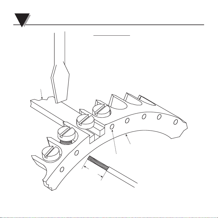
The quick wire ring acts to guide the stripped lead directly under
the head of the terminal screws. At that point the screw can be
Lowered t fasten the wire securely (see diagram, page 2-2).
02-1
2
SW14 Series Wiring Procedure
Page 9
2-2
2 SW 14 Series Wiring Procedure
SWITCHING
QUICK WIRE RING
#35 IS COMMON
LINK
WIRING PROCEDURE:
1. STRIP LEAD WIRE 5/16".
2. TWIST LEAD IF USING STRANDED TYPE WIRE.
3. WITH A SLOTTED SCREWDRIVER, RAISE SCREW
HIGH ENOUGH TO CLEAR WIRE DIAMETER.
4. INSERT STRIPPED LEAD THRU HOLE IN THE
QUICK WIRE RING AND UNDER THE SHOULDER
OF THE SCREW HEAD.
5. TURN SCREW TO SECURE WIRE.
6. DO NOT OVERTIGHTEN.
NOTE: RECOMMENDED WIRE - 20-24 GAGE
THE O3 5/8" PANEL CUTOUT FOR MOUNTING THE
SWITCH LIMITS THE PREWIRING OF HEA
VIER
GAGE
WIRE UNTIL AFTER THE SWITCH IS MOUNTED TO
THE PANEL.
35
34
33
32
31
1
2
5/16"
MIN.
NOTE: THE QUICK WIRE RING
IS REQUIRED AS A BARRIER
TO ISOLATE CONTACTS.
Figure 2-1. SW14 Series Wiring Procedure
Page 10
02-3
SW 14 Series Wiring Procedure 2
–
INSTRUMENT
EXAMPLE: 6 POSITION
2 POLE WIRING
(USE T/C WIRE BETWEEN
SENSOR, SWITCH &
INSTRUMENT)
#6-32 HEX NUT
5/8 DIA. FLAT WASHER
#6 LOCK WASHER
NOTE:
THE QUICK WIRE RING HAS BEEN
REMOVED FROM ILLUSTRATION FOR
CLARITY, HOWEVER, THE QUICK WIRE
RING IS REQUIRED AS A BARRIER TO
ISOLATE CONTACTS.
BOTTOM VIEW
OF SWITCH
T/C
SHORTING LINK
(OFF POSITION
ALWAYS)
TOP VIEW
OF SWITCH
CONTACT RINGS
(COMMON)
+
+
–
–
+
(USE COPPER WIRE BETWEEN
SWITCH & INSTRUMENT)
SERIES 900 THERMISTOR
or 2 WIRE RTD
SECURITY FASTENERS RETAIN THE
QUICK WIRE RING AND ARE NOT IN
THE ELECTRICAL CIRCUIT
Figure 2-2. SW14 Series 2 Pole Wiring
Page 11

2 SW14 Series Wiring Procedure
2-4
BLACK
RED
BLACK
COM.
COM.
(USE COPPER WIRE
BETWEEN SWITCH
& INSTRUMENT)
3-WIRE RTD
SECURITY FASTENERS RETAIN THE
QUICK WIRE RING AND ARE NOT IN
THE ELECTRICAL CIRCUIT
–
INSTRUMENT
EXAMPLE: 6 POSITION
3 POLE WIRING
#6-32 HEX NUT
5/8 DIA. FLAT WASHER
#6 LOCK WASHER
NOTE:
THE QUICK WIRE RING HAS BEEN
REMOVED FROM ILLUSTRATION FOR
CLARITY, HOWEVER, THE QUICK WIRE
RING IS REQUIRED AS A BARRIER TO
ISOLATE CONTACTS.
BOTTOM VIEW
OF SWITCH
TOP VIEW
OF SWITCH
CONTACT RINGS
(COMMON)
+
+
–
Figure 2-3. SW14 Series 3 Pole Wiring
Page 12

12-5
SW14 Series Wiring Procedure 2
4 WIRE
CONFIGURATION
2 WIRE CONFIGURATION
PLUS LOOP
SECURITY FASTENERS RETAIN THE
QUICK WIRE RING AND ARE NOT IN
THE ELECTRICAL CIRCUIT
–
RED
BLACK
INSTRUMENT
EXAMPLE: 6 POSITION
4 POLE WIRING
#6-32 HEX NUT
5/8 DIA. FLAT WASHER
#6 LOCK WASHER
NOTE:
THE QUICK WIRE RING HAS
BEEN REMOVED FROM
ILLUSTRATION FOR CLARITY,
HOWEVER, THE QUICK WIRE
RING IS REQUIRED AS A
BOTTOM VIEW
OF SWITCH
TOP VIEW
OF SWITCH
CONTACT RINGS
(COMMON)
+
+
––
–
+
(USE COPPER WIRE
BETWEEN SWITCH
& INSTRUMENT)
4-WIRE RTD
BLACK
RED
BLACK
RED
RED
BLACK
+
–
Figure 2-4. SW14 Series 4 Pole Wiring
Page 13

3.1 Mounting the switch into a 1/4 DIN Panel Cutout
1. Cut out jack panel to 3.622" x 3.622" (92mm x 92 mm
dimensions.
2. Pass the switch through the panel cutout.
3. Apply the hardware provided in the order shown in Figure 3-1.
4. Tighten nuts.
5/8 DIA. FLAT WASHER
#6-32 HEX NUT
#6 LOCK W
ASHER
PAN EL
CUTOUT
PANEL
SELECTOR
SWITCH
Figure 3-1. 1/4 DIN Panel Mounting
3-1
3 SW 14 Series Mounting Procedure
Page 14

03-2
3.2 Standard Panel Mounting
1. Use the template provided to make a panel cut.
2. Pass the switch through the panel cutout, aligning the
mounting studs through the holes.
3. Apply the hardware provided in the order shown in Figure 3-2.
4. Tighten nuts.
5/8 DIA. FLAT WASHER
#6-32 HEX NUT
#6 LOCK W
ASHER
PANEL
SELECTOR
SWITCH
Figure 3-2. Selector Switch Standard Panel Mounting
OSW Series Mounting Procedure 3
Page 15

3 SW14 Series Mounting Procedure
3-3
45 10'
No. 18 (0.1695) DRILL
4 HOLES EQUALLY SPACED
(STANDARD WITH JACK PANELS)
E
F
HOLE PATTERN
C
B
A
4 POLE
3 POLE
2 POLE
PAN EL
D
Page 16

3-4
EXTENSION BEZEL
5/8 DIA. FLAT WASHER
#6-32 HEX NUT
#6 LOCK WASHER
PANEL
IN THE EVENT THAT THE PANEL CUTOUT
EXCEEDS THE RECOMENDED DIAMETER OF
3 1/2" BUT IS LESS THAT 4 1/4", AN
EXTENSION BEZEL (INCLUDED W/PRODUCT)
MAY BE INSTALLED BETWEEN THE FACEPLATE
OF THE 1/4 DIN SWITCH AND THE PANEL
IT IS BEING MOUNTED TO, USING STANDARD
HARDWARE.
1/4 DIN
SELECTOR
SWITCH
SW14 Series Mounting Procedure 3
Figure 3-4. Installing an Extension Bezel
Page 17

4-1
4
SW14 Series Specifications
Insulation Resistance: 20MΩ at 300 volts dc
Contact Resistance: 0.004Ω or less
Case Material: Noryl SPN-420
Weight:
2-pole switch: 3/4 lbs.
3-pole switch: 1 lb.
4-pole switch: 1 1/4 lb.
Hardware and box: 3/4 lbs.
Continuous Use
Temperature: 110°C
Page 18

5
OSW Series Introduction
5.1 General Description
The OSW Series rotary selector switches are designed to
provide isothermal, low-resistance switching in your temperature
measuring circuits. the isothermal design minimizes temperature
gradients between the input and the output thermocouple wiring
to avoid the generation of thermal EMF’s that add error to your
thermocouple temperature measuring circuits. Temperaturesensitive resistance transducers such as RTD’s and thermistors
can be switched with confidence, knowing that the low contact
resistance will not add any appreciable error to the measurement.
The OSW two-pole switches are available in either 3" or 5"
diameter housing, depending on the number of positions (refer to
Selection Guides on page 5-2). All of the three-pole versions have
a 5" diameter housing. Two to 40 positions, in addition to OFF,
are available in a designer style unbreakable Noryl case. (Note
that the 3-pole version has no OFF position).
To allow matching of a readout device in all switch positions, the
“off” position of each switch may be shorted of left as an open
circuit. Each pole is fully isolated. For quick and easy wiring, the
terminals located at the rear of the switch are clearly marked.
All switches are available with the standard round knob, or a
pistol-grip handle, and gold or silver plated contacts.
5-1
Page 19

5-2
Page 20

6
OSW Series Wiring Procedure
6.1 Wiring Procedure
In most cases, the switches are used to connect one of several
Alternative sensor inputs to a single instrument. The instructions
that follow apply to this usual case. However, the rotary switch is
bi-directional and can also connect a single input to one of
several outputs.
When an OSW switch is used for thermocouple circuitry, make
sure that the switch terminals are in a uniform temperature
environment. Avoid hot or cool air drafts. Environmental
temperature gradients can introduce error in thermocouple
readings in spite of the switch’s isothermal design.
The switch input wiring connections are at the rear of the housing,
arranged in concentric rings. The outermost ring is labeled “+”,
the next is “-”, and in three-pole models, the innermost ring is
labeled “COM”. The output terminals are inside the concentric
rings of terminals and are labeled “+,-,COM” to match the inputs.
Attach the input and output leads to the terminals with the screws
and washers supplied in a separate package with each rotary
switch.
6-1
Page 21

6-2
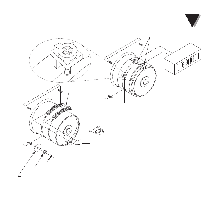
6 OSW Series Wiring Procedure
The switches are also supplied with a screw and nut to provide
a short circuit for the OFF position, if desired. Figure 6-1 shows
the terminal configuration of the two-pole models as well as the
attachment hardware. Figure 6-2 shows the wiring configuration
for two-pole models. Figures 6-3 and 6-4 show the terminal
configuration and wiring for three-pole switches.
Page 22

6-3
OFF
1
4
7
14
#4-40 x 1/2 PAN HEAD SCREW
(SHORTING SCREW)
OFF POSITION
SHORTING SCREW ASSEMBLY
#4-40 NUT
TYPICAL HARDWARE
ASSEMBLY
#6 FLAT WASHER
#6 LOCK WASHER
#6-32 HEX NUT
Figure 6-1. OSW Two-Pole Switch and Hardware - Rear View
SW14 Series Wiring Procedure 6
Page 23

6-4
6 OSW Series Wiring Procedure
SERIES 900 THERMISTER*
(+)
(–)
(+)
(–)
EITHER
OR
THERMOCOUPLE**
* USE COPPER WIRE FOR
HOOK UP
** USE THERMOCOUPLE WIRE
FOR HOOK UP
INSTRUMENT
(+)
(–)
Figure 6-2. OSW Two-Pole Switch and Hardware - Rear View
Page 24

6-5
OSW Series Wiring Procedure 6
Figure 6-3. OSW Three-Pole Switch (hardware not shown)
Rear View
Page 25

6 OSW Series Wiring Procedure
6-6
(+)
COM
RTD SENSOR
INSTRUMENT
(+)
(–)
NOTE: USE COPPER
WIRE FOR HOOK UP
(–)
BLACK
RED
BLACK
COM
COM
Figure 6-4. OSW Three-Pole Wiring
Page 26

1. Use the template provided to make a panel cutout.
2. Pass the switch through the panel cutout, aligning the
mounting studs through the holes.
3. Apply the hardware provided in the order shown in Figure 7-1.
4. Tighten nuts.
7-1
7
OSW Series Mounting Procedure
Figure 7-1. Mounting the Selector Switch
5/8 DIA. FLAT WASHER
#6-32 HEX NUT
#6 LOCK W
ASHER
PANEL
SELECTOR
SWITCH
Page 27

7-2
F
HOLE PATTERN
NO. 18 (0.1695) DRILL
4 HOLES EQUALLY SPACED
G
.45° ± 10'
3 Pole
E
A
D
B
C
Page 28

17-3
EXTENSION BEZEL
5/8 DIA. FLAT WASHER
#6-32 HEX NUT
#6 LOCK WASHER
PANEL
IN THE EVENT THAT THE PANEL CUTOUT
EXCEEDS THE RECOMMENDER DIAMETER,
AN EXTENSION BEZEL (INCLUDING W/PRODUCT)
MAY BE INSTALLED BETWEEN THE FACEPLATE
OF THE SWITCH AND THE PANEL IT IS BEING
MOUNTED TO. USING STANDARD HARDWARE.
SELECTOR
SWITCH
OSW Series Mounting Procedure 7
Figure 7-3. Installing an Extension Bezel
Page 29

8-1
8
OSW Series
Specifications
Insulation Resistance: 20MΩ at 300 volts dc
Contact Resistance: 0.004Ω or less
Case Material: Noryl 731
Weight:
3" switch: 3/4 lbs.
5" switch: 1 1/4 lbs.
Hardware and box: 3/4 lbs.
Continuous Use
Temperature: 110°C
Page 30

8
8-2
NOTES
Page 31

WARRANTY/DISCLAIMER
OMEGA ENGINEERING, INC. warrants this unit to be free of defects in materials and
workmanship for a period of 13 months from date of purchase. OMEGA’s WARRANTY adds an
additional one (1) month grace period to the normal one (1) year product warranty to cover
handling and shipping time. This ensures that OMEGA’s customers receive maximum coverage
on each product.
If the unit malfunctions, it must be returned to the factory for evaluation. OMEGA’s Customer
Service Department will issue an Authorized Return (AR) number immediately upon phone or
written request. Upon examination by OMEGA, if the unit is found to be defective, it will be
repaired or replaced at no charge. OMEGA’s WARRANTY does not apply to defects resulting
from any action of the purchaser, including but not limited to mishandling, improper interfacing,
operation outside of design limits, improper repair, or unauthorized modification. This WARRANTY is
VOID if the unit shows evidence of having been tampered with or shows evidence of ha ving been
damaged as a result of excessive corrosion; or current, heat, moisture or vibration; improper
specification; misapplication; misuse or other operating conditions outside of OMEGA’s control.
Components in which wear is not warranted, include but are not limited to contact points, fuses,
and triacs.
OMEGA is pleased to offer suggestions on the use of its various products. However,
OMEGA neither assumes responsibility for any omissions or errors nor assumes
liability for any damages that result from the use of its products in accordance with
information provided by OMEGA, either verbal or written. OMEGA warrants only that
the parts manufactured by the company will be as specified and free of defects.
OMEGA MAKES NO OTHER WARRANTIES OR REPRESENTATIONS OF ANY KIND
WHATSOEVER, EXPRESSED OR IMPLIED, EXCEPT THAT OF TITLE, AND ALL IMPLIED
WARRANTIES INCLUDING ANY WARRANTY OF MERCHANTABILITY AND FITNESS
FOR A PARTICULAR PURPOSE ARE HEREBY DISCLAIMED. LIMITATION OF LIABILITY:
The remedies of purchaser set forth herein are exclusive, and the total liability of
OMEGA with respect to this order, whether based on contract, warranty, negligence,
indemnification, strict liability or otherwise, shall not exceed the purchase price of
the component upon which liability is based. In no event shall OMEGA be liable for
consequential, incidental or special damages.
CONDITIONS: Equipment sold by OMEGA is not intended to be used, nor shall it be used: (1) as
a “Basic Component” under 10 CFR 21 (NRC), used in or with any nuclear installation or activity;
or (2) in medical applications or used on humans. Should any Product(s) be used in or with any
nuclear installation or activity, medical application, used on humans, or misused in any way,
OMEGA assumes no responsibility as set forth in our basic WARRANTY/ DISCLAIMER language,
and, additionally, purchaser will indemnify OMEGA and hold OMEGA harmless from any
liability or damage whatsoever arising out of the use of the Product(s) in such a manner.
Page 32

M1940/0907
TEMPERATURE
䡺⻬
Thermocouple, RTD & Thermistor
Probes, Connectors, Panels & Assemblies
䡺⻬
Wire: Thermocouple, RTD & Thermistor
䡺⻬
Calibrators & Ice Point References
䡺⻬
Recorders, Controllers & Process Monitors
䡺⻬
Infrared Pyrometers
PRESSURE, STRAIN
AND FORCE
䡺⻬
Transducers & Strain Gages
䡺⻬
Load Cells & Pressure Gages
䡺⻬
Displacement Transducers
䡺⻬
Instrumentation & Accessories
FLOW/LEVEL
䡺⻬
Rotameters, Gas Mass Flowmeters
& Flow Computers
䡺⻬
Air Velocity Indicators
䡺⻬
Turbine/Paddlewheel Systems
䡺⻬
Totalizers & Batch Controllers
pH/CONDUCTIVITY
䡺⻬
pH Electrodes, Testers & Accessories
䡺⻬
Benchtop/Laboratory Meters
䡺⻬
Controllers, Calibrators, Simulators
& Pumps
䡺⻬
Industrial pH & Conductivity Equipment
DATA ACQUISITION
䡺⻬
Data Acquisition &
Engineering Software
䡺⻬
Communications-Based
Acquisition Systems
䡺⻬
Plug-in Cards for Apple, IBM
& Compatibles
䡺⻬
Datalogging Systems
䡺⻬
Recorders, Printers & Plotters
HEATERS
䡺⻬
Heating Cable
䡺⻬
Cartridge & Strip Heaters
䡺⻬
Immersion & Band Heaters
䡺⻬
Flexible Heaters
䡺⻬
Laboratory Heaters
ENVIRONMENTAL
MONITORING AND CONTROL
䡺⻬
Metering & Control Instrumentation
䡺⻬
Refractometers
䡺⻬
Pumps & Tubing
䡺⻬
Air, Soil & Water Monitors
䡺⻬
Industrial Water & Wastewater
Treatment
䡺⻬
pH, Conductivity & Dissolved
Oxygen Instruments
Where Do I Find Everything I Need for
Process Measurement and Control?
OMEGA…Of Course!
Shop online at omega.com
SM
 Loading...