

Page 1

http://www.omega.com
e-mail: info@omega.com
OSP SERIES
Portable IR thermometers
Page 2

OMEGAnetSM On-Line Service
Internet e-mail
http://www.omega.com
USA:
ISO 9001 Certified
Canada:
Usa and Cana da:
Mexico and
Latin America:
Servicing North America:
One Omega Drive, Box 4047
Stamford, CT 06907-0047
Tel: (203) 359-1660
e-mail: info@omega.com
976 Bergar
Laval (Quebec) H7L 5A1
Tel: (514) 856-6928
e-mail: info@omega.ca
For immediate tech nic al or ap p l ic ati on as s is ta nce :
Sales Service: 1-800-826-6342 / 1-800-TC-OMEGA
Customer Service: 1-800-622-2378 / 1-800-622-BEST
Engineering Service: 1-800-872-9436 / 1-800-USA-WHEN
TELEX: 996404 EASYLINK: 62968934 CABLE: OMEGA
Tel: (95) 800-826-6342
En Español: (95) 203-359-7803
e-mail: espanol@omega.com
SM
SM
SM
Servicing Europe:
info@omega.com
FAX: (203) 359-7700
FAX: (514) 856-6886
FAX: (95) 203-359-7807
Benelux:
Czech Repu blic:
France:
Germany/Austria:
United Kingdom:
ISO 9002 Certified
It is the policy of OMEGA to comply with all worldwide safety and EMC/EMI regulations that apply. OMEGA is constantly
pursuing certification of its products to the European New Approach Directives. OMEGA will add the CE mark to every
appropriate device upon certification.
The information contained in this document is believed to be corrected but OMEGA Engineering Inc. accepts no liability for any errors it
WARNING
: These products are not designed for use in, and should not be used for, patient connected applications.
Postbus 8034, 1180 LA Amstelveen, The Netherlands
Tel: (31) 20 6418405
Toll Free in Benelux: 0800 0993344
e-mail: nl@omega.com
ul. Rude armady 1868, 733 01 Karvina-Hranice, Czech Republic
Tel: 420 (69) 6311899
Toll free: 0800-1-66342
e-mail: czech@omega.com
9, rue Denis Papin, 78190 Trappes
Tel: (33) 130-621-400
Toll Free in France: 0800-4-06342
e-mail: france@omega.com
Daimlerstrasse 26, D-75392 Deckenpfronn, Germany
Tel: 49 (07056) 3017
Toll Free in Germany: 0130 11 21 66
e-mail: info@omega.de
One Omega Drive , River Bend Technology Centre
Northbank, Irlam, Manchester
M44 5EX, Engl and
Tel: 44 (161) 777-6611
Toll Free in United Kingdom: 0800-488-488
e-mail: info@omega.co.uk
contains, and reserves the right to alter specifications without notice.
FAX: (31) 20 6434643
FAX: 420 (69) 6311114
FAX: (33) 130-699-120
FAX: 49 (07056) 8540
FAX: 44 (161) 777-6622
2
Page 3
INTRODUCTORY NOTE
This user’s guide contains operating instructions, as well as a description of the principles of operation, of the
OSP Series portable IR thermometers.
This information covers all models of the instrument, including the basic equipment and its options and
accessories.
This manual is a complete “USER GUID E”, providing st ep-by-step i nstructio ns to operate th e instrum ent in
each of its designed functions.
OMEGA has used care and effort in preparing this guide and believes the information in this publication to be
accurate. OMEGA products are subjected to cont inuous improvement, in order to pursue the techn ological
leadership; these improvements could require changes to the information of this guide.
OMEGA reserves the right to change such information without notice.
No part of this document may be stored in a retrieval system, or transmitted in any form, electronic or
mechanical, without prior written permission of OMEGA Engineering Inc.
OSP portable IR thermometers use sophisticated analogic and digital technologies. Any maintenance
operation must be carried out by qualified personne l
any support requirements.
When Ni-MH rechargea ble batteries are ordered, th e unit can be powered also by 115V
supply using the special power supply module provided.
OSP is fully tested in conformity with the directive n°89/336/CEE Electromagnetic Compatibility. OMEGA
shall not be liable in any event, for technical or publishing error or omissions, or for any incidental and
consequential damages, in connection with, or arising out of the use of this guide.
. We recommend you c ontact our technicians f or
ONLY
±
10% 50/60Hz line
B
IMPORTANT :
Danger and Certification Labels
Labels Location – refer to section 8.2
Warnings and Cautions – refer to section 8.1
EFORE USING THE
THEM AVAIABLE FOR FUTURE REFERENCE
OSP
FOR THE FIR S T TIME, GO OVER THESE OPERATING INSTRUCTIONS CAREFULLY AND KEEP
.
3
Page 4

TABLE OF CONTENTS
1 GENERAL DESCRIPTION...................................................................................................................6
1.1 Instrument codes..............................................................................................................................................7
1.2 Specifications ...................................................................................................................................................8
2 GENERAL FEATURES ........................................................................................................................9
2.1 General.............................................................................................................................................................9
2.2 Optical System .................................................................................................................................................9
2.3 Target pinpointing.............................................................................................................................................9
2.4 Taking measurements......................................................................................................................................9
2.5 Keyboard ........................................................................................................................................................10
2.6 Display............................................................................................................................................................10
2.7 Digital Interface...............................................................................................................................................10
2.8 Self calibration................................................................................................................................................10
2.9 Thermocouple Input........................................................................................................................................10
2.10 Analog Output ................................................................................................................................................10
2.11 Logging Mode.................................................................................................................................................11
2.12 Calculated Measurements..............................................................................................................................11
2.13 Case ...............................................................................................................................................................11
2.14 Logging Data Manager...................................................................................................................................11
3 PHYSICAL DESCRIPTION ................................................................................................................12
4 FUNCTIONAL DESCRIPTION ...........................................................................................................13
4.1 Power supply..................................................................................................................................................13
4.2 Keyboard ........................................................................................................................................................13
4.3 Microcontroller................................................................................................................................................14
4.4 Firmware ........................................................................................................................................................14
4.5 Display............................................................................................................................................................14
4.6 Battery charger...............................................................................................................................................14
4.7 Digital interface...............................................................................................................................................14
5 UNPACKING ......................................................................................................................................15
6 PRE-OPERATIONAL CHECK ...........................................................................................................16
7 POWER SUPPLY...............................................................................................................................17
7.1 Rechargeable batteries ..................................................................................................................................17
7.1.1 How to maximize the life span of the battery .............................................................................................17
7.2 Power supply with alkaline batteries...............................................................................................................17
7.3 Power supply from main line AC.....................................................................................................................17
8 WARNINGS & CAUTIONS.................................................................................................................18
8.1 Laser Sight .....................................................................................................................................................18
8.2 Analogue input................................................................................................................................................18
8.3 Danger and Certification Labels .....................................................................................................................18
9 OPERATIONS ....................................................................................................................................20
9.1 Quick Start......................................................................................................................................................20
9.2 How to Operate the instrument.......................................................................................................................20
9.3 Hold ................................................................................................................................................................21
9.4 Laser sighting .................................................................................................................................................21
9.5 Unstable temperature measurement ..............................................................................................................22
9.6 Alarm settings.................................................................................................................................................23
9.7 Thermocouple input........................................................................................................................................24
9.8 Minimum, maximum, average and difference indication.................................................................................25
9.9 Automatic Emissivity Setting ..........................................................................................................................26
10 CONFIGURATION..............................................................................................................................27
10.1 Technical Unit selection..................................................................................................................................27
10.2 Thermocouple input enabled ..........................................................................................................................27
10.3 Temperature Scale selection..........................................................................................................................27
10.4 Date & Real Time clock setting ......................................................................................................................28
10.5 Acquisition settings.........................................................................................................................................28
10.6 Buzzer On/Off.................................................................................................................................................29
10.7 OSP 500/800 decimal point selection.............................................................................................................29
10.8 Ambient Temperature Compensation (TAM)..................................................................................................29
10.9 Firmware revision number..............................................................................................................................30
10.10 Instrument serial number...........................................................................................................................30
10.11 Battery level of charge ...............................................................................................................................31
4
Page 5

11 DATA ACQUISITION OPERATIVE MODE........................................................................................32
11.1 How to operate in data acquisition mode........................................................................................................32
11.2 Recall stored data...........................................................................................................................................34
12 LOGGING DATA MANAGER ............................................................................................................35
12.1 Installation ......................................................................................................................................................35
12.2 Program Architecture.................................................................................................................................35
12.2.1 Toolbars.....................................................................................................................................................37
12.3 Quick starting .................................................................................................................................................38
13 OPTIONS & ACCESSORIES .............................................................................................................42
13.1 Printer operations ...........................................................................................................................................42
13.2 Sighting telescope system..............................................................................................................................42
13.3 Red Point pinpointing system .........................................................................................................................43
14 APPLICATION NOTES ......................................................................................................................45
14.1 Infrared energy ...............................................................................................................................................45
14.2 Applications ....................................................................................................................................................45
14.3 Emissivity...................................................................................................................................................45
14.4 Reflected energy compensation.....................................................................................................................45
15 DIGITAL INTERFACE........................................................................................................................46
15.1 Digital output wiring practice...........................................................................................................................46
15.2 TTL to RS 232 adapter...................................................................................................................................46
15.3 Communication protocol.................................................................................................................................47
15.3.1 Computer data request from OSP to PC ...................................................................................................47
15.3.2 Computer data setting from PC to OSP.....................................................................................................49
15.3.3 Communication programs..........................................................................................................................50
16 MAINTENANCE..................................................................................................................................52
16.1 Faulty operating conditions.............................................................................................................................52
16.2 Storage...........................................................................................................................................................52
APPENDIX.......................................................................................................................................................53
A1 How to determine an object emissivity ...........................................................................................................54
A1.1 Typical Emissivity Values ..........................................................................................................................54
A1.2 Metals - Typical Emissivity Values.............................................................................................................55
A1.3 Non-metals - Typical Emissivity Values .....................................................................................................56
5
Page 6

1 GENERAL DESCRIPTION
Portable infrared thermometers measure surface temperature without touching the surface. They collect the infrared
energy radiated by a target and compute its surface temperature.
OMEGA OSP Series
enable the monitoring of operating temperatures of mechanical and electrical plants or production equipment without
removing the equipment from the service.
Any temperature variation noticeable in whatever kind of system device should show critical overheating conditions
which may cause malfunctioning to the device itself.
They are also useful to measure product temperatures during manufacturing, to spot problems before they reduce quality
or cause production downtime.
Their principle of operation is very simple, the instrument determines the temperature of an object by measuring the
amount of radiant energy emitted by it.
The detector, installed on each
amount of energy received, and therefore is a function of the temperature of the target. By sampling and manipulating
the output of the detector, the microcontroller-based electronics can display the temperature and the related computed
values such as maximum, minimum, average, and difference temperatures seen during the measurement. The same
information can also be stored and processed via Personal Computer (using electronic spreadsheets e.g. Lotus, Excel,
Paradox, etc.). The displayed value can be printed out directly into an external printer supplied on request.
Thanks to its advanced optical system and electronics,
operate in critical ambient conditions.
To take measurements by using
trigger can be locked on if desired. For more distant targets, hold the unit at arm length and use the sighting notch and
post to aim. This will give a parallel and offset sighting. Also Laser beam is available for sighting target.
Temperature information as well as auxiliary parameter pieces of information are shown on the high contrast liquid
crystal display (LCD).
The case, made in shock-resistant ABS + polycarbonate, is ergonomically designed for an easy practical use.
The instrument is powered by a group of four alkaline or Ni-MH rechargeable batteries (AA type); an external battery
charger module is supplied as a standard accessory.
OSP
portable IR thermometers have been developed using the most advanced microcontroller technique to provide high
accuracy on extended ranges and a powerful operating flexibility.
The calibration uses computerized procedures and the relevant calibration data are memory stored to ensure high
accuracy.
are portable infrared temperature devices designed to ease maintenance operations. They also
OSP
unit, responds by producing a voltage signal which is directly proportional to the
OSP
can be very useful for objects 5mm and larger and can
OSP
thermometers just pull the trigger and then point at the target to be measured. The
General features
OSP
non contact infrared thermometers are designed to simplify temperature measurements at distance from a target
and to identify hot spots, which normally means anomalous operative conditions avoiding costly downtime or processing
problems that lead to rejected products. There is no need to focus as required by photographic equipment. Accurate
measurements result if
Innovative design
This new line of portable instruments represents the most versatile and powerful infrared temperature system.
The most appropriate aiming system at the application can be selected with a twin laser pinpointing or with a combination
of twin lasers and telescope or red point for true universal applications.
An on board data logger is available to store up to 500 data points, an analogue output can drive directly a recorder or a
controller, The real-time temperature can be displayed together with the Maximum, Minimum, Difference and Average
values.
Each model incorporates the following :
• high quality optical system
• high sensitivity infrared radiation detector
• auxiliary input for thermocouple type K and S
• microcontroller circuit
• high contrast LCD display with backlight device
• extended life traditional microswitch keyboard
• four alkaline or rechargeable Ni-MH type AA batteries
• external module for battery charge and/or line operation
• analogue output
• digital interface
OSP
field of view diameter is smaller than the target.
6
Page 7

1.1 Instrument codes
To Order
Model No. Temperature
Range
OSP500-(*)
OSP800-(*)
OSP1000-(*)
OSP1300-(*)
OSP1600-(*)
OSP2000-(*)
* Insert suffix codes B and C and D from options chart above
** See Target spot size diagram
Note
: all accessories and options must be specified at time of order.
Each Pyrometer supplied with
–30 °C to +930 °C
-20°F to +1706°F
–30 °C to +930 °C
-20°F to +1610°F
–30 °C to +1000 °C
-20°F to +1830°F
+300 °C to +1300 °C
+570°F to 2370°F
+600 °C to +1600 °C
+1120°F to 2900°F
+600 °C to +2000 °C
+1120°F to +3630°F
: Alkaline battery, laser, operators manual, and calibration report
Options
Suffix Code Description OSP500 OSP800 OSP1000 OSP1300 OSP1600 OSP2000
-B0
-B1
-C1
-C2
-C3
-C4
-D1
-D2
-D3
-D6
-D7
-D8
-D9
-DA
Alkaline battery std std std std std std
Rechargeable Battery Opt Opt Opt Opt Opt Opt
Single Laser Std No No No No No
Twin crossed Lasers No Std Std Std Std Std
Twin normal Lasers No Std Std std Std Std
Single Laser with Circle Std No No No No No
Vinyl Case Std Std No std Std No
Aluminum Case Opt Opt Std Opt Opt Std
Memory+Software+RS232 Cable Opt Opt Std Opt Opt Std
Sighting telescope No No Opt Opt Opt Opt
Red Point No No No Opt Opt Opt
Alarms Std Std Std std std Std
Analog Output Opt Std std std std Std
Aux Input for Tc K & S Opt std std std std Std
Report of Calibration std std std std std Std
No = Not available Std = Standard at no extra cost
Spectral
Response
8 to 14 µm
8 to 14 µm
8 to 14 µm
1.6 µm
1 µm
1 µm
Target Spot Size
@ Distance **
10mm @ 600mm
0.39 @ 24”
10mm @ 600mm
0.39 @ 24”
10mm @ 1000mm
0.39 @ 39.4”
6mm @ 1000mm
0.236 @ 39.4”
5mm @ 1000mm
0.20 @ 39.4”
5mm @ 1000mm
0.20 @ 39.4”
D/S Optical Ratio
60:1
60:1
100:1
167:1
200:1
200:1
Single laser
Single laser with circle
Twin crossed lasers
Twin normal lasers
Red Point
Sighting Telescope
Software
: General application, target center
: General application, target center plus target dimension with circle (short distance)
: General application, target dimension
(parallel): Long distance application over 5m (16’)
: High temperature over 1250°C 1x
: High temperature over 1250°C 2x tele
(D3): Includes memory up to 500 values. You can divide them by Tag (20 different). Each value includes
temperature value and date&time (built in real time clock). Tag name with 7 characters on instrument
display. Datalogging manual or automatic with sampling time from 1 to 999 sec. Windows 95 software to
download data to PC and cable. You can view, save, print, export to Excel and graph data.
U.S. and international Patents and Patents Pending.
7
Page 8
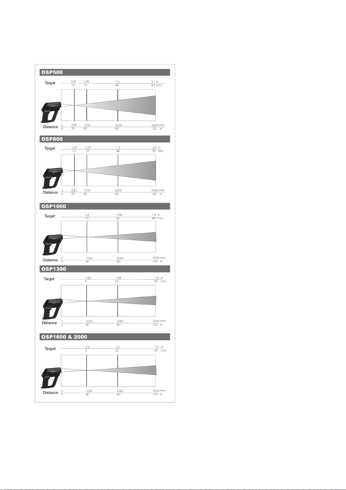
1.2 Specifications
Target dimensions at different distances
Nominal target diameter at 95% energy
• Temperature measuring ranges:
-30 to 2000°C (-22 to 3632°F)
•
Thermocouple measuring ranges:
type K :
-100°C to +1370°C (-148 to 2500°F) 0.1°C resolution
type S :
•
•
• Repeatability IR:
• Temperature stability IR:
•
•
•
•
• Emissivity:
•
•
• Calculated functions:
•
•
• Laser:
•
•
• Battery low level of charge:
• Line operation:
•
•
• Operating environment temperature range:
• Storage temperature range:
• Case:
• Dimensions:
•
0°C to +1760°C (-32 to 3200°F) 0.1°C resolution
Spectral response:
OSP 500, 800 & 1000 :
OSP 1300 :
OSP 1600 & 2000
Accuracy:
OSP 500, 800 & 1000:
OSP 1300, 1600 & 2000:
OSP 500, P800 & P1000 :
OSP 1300, P1600 & P2000:
for the band exceeding +18°C to +28°C:
Display:
High contrast custom LCD with backlight device
Display resolution:
1°C / °F / K (0.1°C/0.1°F in AVG mode up to 200°C)
Alarms:
Acoustic and visible
Measurement sampling time:
<300 ms
Adjustable from 0.10 to 1.00 in 0.01 steps
Analog output:
1 mV/ °C/ °F/ K
Digital interface:
full bi-directional TTL level port
Optional TTL to RS232 adapter
Hold, average, max, min, ∆T
Data memory:
500 input data structured by tag
Calibration:
self learning technique with automatic procedure
Wavelength
Maximum optical power
FDA Classification
Subchapter J
Safety classi fication
Beam diameter
Beam divergence
Laser indicator
Power supply:
alkaline or rechargeable type AA battery
Battery life:
16 h (with backlight off)
symbol on the LCD display
100, 115, 230 Vac through the external charger
Charger transformer insulation:
2500 V
Battery recharging time:
8 h at 90% (instrument switched off)
from -10°C to +55°C (-14 to 131°F)
from -30 °C to +60 °C (-22 to 140°F) without battery
Injection moulded ABS+ policarbonate
200 x 180 x 80 mm (7.87 x 7.09 x 3.15”)
Weights:
net 0.8 kg (1.76 lb); gross 1.5 kg (3.3 lb)
1.6 µm
: 650nm
: 3mm
: asterisk on display
8 - 14 µm
0.9 µm
±(1% of the reading +1°C/2°F)
±(0.5% of the reading +1°C/2°F)
±0.5% of the reading
±0.25% of the reading
±0.01% of f.s./°C
: <1mW
: Class II, Complies with 21CFR Chapter 1,
: Class 2
: <0.5mrad
8
Page 9

2 GENERAL FEATURES
2.1 General
Temperature measurements of a liquid or gaseous compound have been successfully made with thermoelectric or
expansion thermometers thanks to the good thermal exchange of the sensor with the fluid.
With solid bodies a good thermal exchange is difficult to be obtained and an additional measuring error should be
considered.
A direct contact measurement is impractical when the object being measured is moving, it cannot be touched with a
thermoelectric sensor because of electrical hazard or of other reasons.
A non-contact IR temperature measurement is the best solution to the above application problems.
Also other applications benefit because non-contact thermometers do not add or remove heat or disturb the process in
any way, and there is no wear and tare on the instrument.
2.2 Optical System
The optical system is equipped with a main objective to focus the infrared energy into the infrared detector through a
single lens, a filter and a field stop which defines the visual cone and therefore the target dimensions.
As the detector is placed in the focal point of the measurement portion of the optical system no focusing operations are
required.
A secondary, but extremely important objective, is the correct pinpointing of the target as described below.
The optical diagrams are shown in the previous specification section.
2.3 Target pinpointing
A correct aiming at the target is an important factor of a non-contact thermometer. The immediate evaluation of the
smallest measurable target area is also a positive key factor in many applications.
The following types of pinpointing are available :
• A “V” groove on the up side of the instrument can be used stretching the arm.
• Twin laser pointers to define, at distance, the measurable target dimensions. Two versions are available with crossing
or parallel twin lasers. The twin crossed lasers are suggested for target distance upper than 5 meters.
• Combination of twin lasers and direct telescope viewing for universal applications mainly required for a high distance
targets (more than 10 meters) and high temperature targets (more than 1000 °C) where laser spots are not visible .
• Combination of twin lasers and a red point pinpointing for universal applications mainly required for high temperature
target where laser spots are not visible
With a laser pinpointing the operation of the instrument is extremely simplified. You simply aim at the target and read the
temperature.
The installation procedures for telescope and red point pinpointing, please refers to the dedicated chapters.
2.4 Taking measurements
OSP
portable thermometers are accurate, rugged and compact.
Its modern and practical design allows an easy handling and aiming, either at arm length or using a tripod mount, to
obtain current temperature value, average, minimum, maximum and difference temperature measurement values.
Its analogue to digital outputs allows a continuous documentation on a continuous trace recorder or on a serial printer.
Using the keyboard it is also possible to enable the instrument to measure one of the computed values in addition to the
actual temperature value measurement:
MAX maximum temperature recorded during current measurement
MIN minimum temperature recorded during current measurement
DIF difference between MAX and MlN
AVG average temperature for entire measurement
Tamb ambient temperature
9
Page 10
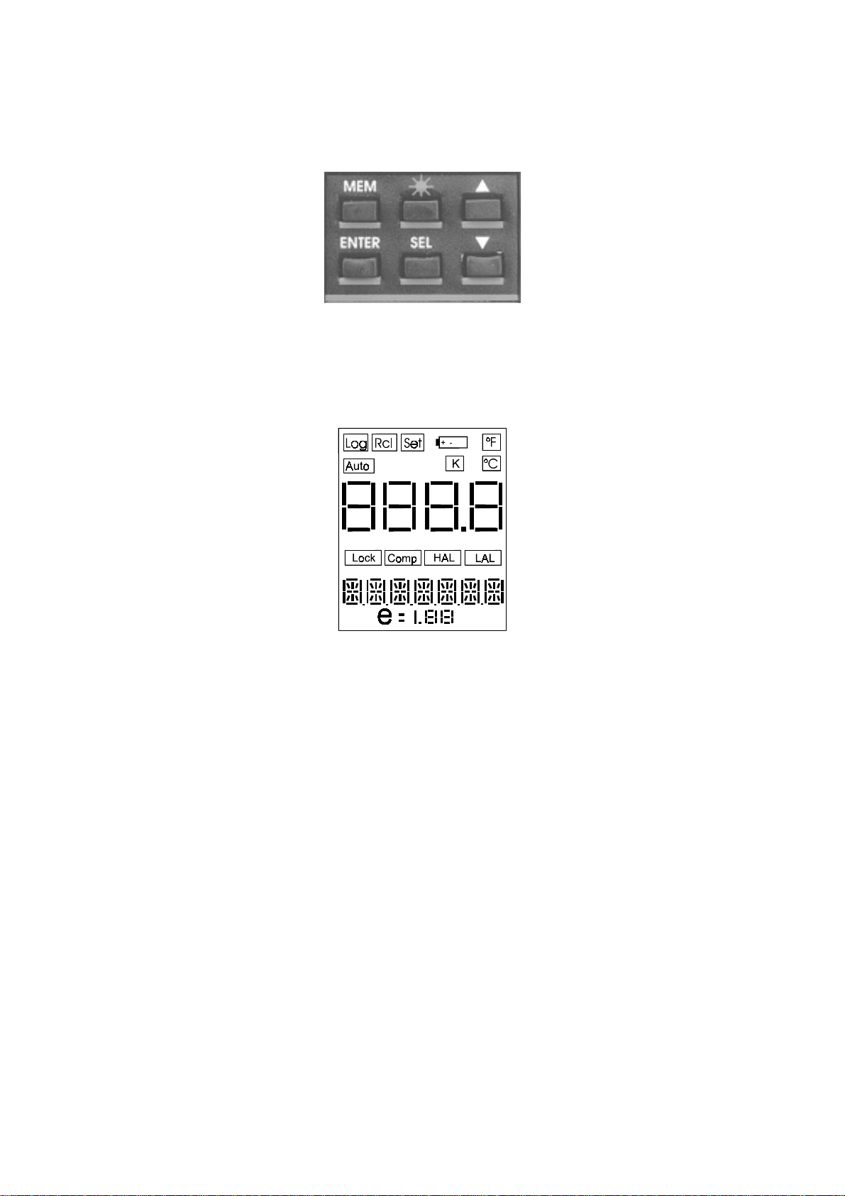
2.5 Keyboard
Traditional metal-click switches, with a working life of one million operations, are used to enter the operator’s instructions.
The contact closure of the keyboard keys is acknowledged, as a coded signal, directly by the microcontroller.
2.6 Display
The high contrast customised alphanumeric LCD display indicates the measured temperature value.
It is also used for operators’ messages, instrument configuration set-up, special operative modes, etc.
It is equipped with a backlight device to allow easy readings even in poor light conditions.
2.7 Digital Interface
A digital interface with TTL logic levels is available for communication with external units. A serial data port provides
communication capability at a logic level of 0-5 V (four wires: Tx, Rx, GND, Vcc).
A special software set enables the transfer of all the recorded data on a Personal Computer for further statistical
analysis.
2.8 Self calibration
The hardware-firmware design allows the automatic calibration of the instrument. The calibration procedure is protected
by a security code.
2.9 Thermocouple Input
To extend the operative capability the instrument is equipped with an auxiliary input for thermocouple.
This feature, when used with a calibrated thermocouple, can be used to obtain accurate temperature measurements
eliminating the problems of emissivity and the interfering light.
The thermocouple can be used to obtain an accurate temperature reading of the target material and then these data are
used to determine the compensation value for the actual emissivity, including the interfering light, within a range from
0.10 to 1.00.
2.10 Analog Output
An analog output (1 mV/°C/°F/K) is available to drive an external analog input device (eg. a potentiometric or hybrid
recorder) for long term trend profiling and tests.
10
Page 11

In this case the instrument can be powered directly from mains using the external power supply module supplied with the
thermometer.
2.11 Logging Mode
The instrument can be equipped with an internal memory to store up to 500 input data.
Two types of data acquisitions can be selected by the user.
Continuous acquisition
The operator can select the interval time between each acquisition and store progressively the input data in the Tag file
or can manually, step by step, give the acquisition instruction.
Acquisition by dedicated tag
Standard Agencies and Quality Auditors require the collection, organization and availability of traceability documents.
A supporting software is available to transfer a selection of plant inspections from a PC to the internal memory of the
instrument in order to simplify field check and select the appropriate tag number.
Dedicated input data are memory stored and downloaded into a PC to document the inspection activity.
Data can be saved on disks, viewed and printed in a numeric or graphic mode.
2.12 Calculated Measurements
For the measurement of unstable input signals by a progressive averaging with a programmable average weight. In
addition the operator can select average, minimum, maximum, Tmax -Tmin, differential.
2.13 Case
The case of the instrument is ergonomically designed for an easy hand held operation and transport.
The body is injection molded, shock-resistant, flame proof ABS+ polycarbonate.
A vinyl case with shoulder strap and an aluminum case for instrument + printer + accessories are available on request.
2.14 Logging Data Manager
LogMan software allows the OSP series users to set and prepare the infrared thermometers to acquire the data
organized by ‘Tag’. This software also allows to download data from Instrument on document (table) with date, time and
value. You can view table, save table, print table, export table in excel-txt-html and obtain graph. You can also manage
data coping, moving on other tables.
11
Page 12

3 PHYSICAL DESCRIPTION
OSP
portable IR thermometers consist of a rugged, compact and self-extinguishing case ergonomically designed for an
easy practical use.
The instrument can be supplied either with a vinyl protective case with shoulder strap or with an aluminum case to
assure better protection against mechanical knocks or scratches.
The battery container is located on the lower part of the handle, and is accessible through a cover fastened by a metal
screw.
12
Page 13
4 FUNCTIONAL DESCRIPTION
j
OSP series infrared portable thermometers block diagram is shown below:
Emitted IR energy
Detector
Analog
Output
Measuring
ob
ect
Optical system
•
Filter
•
Detector
•
Amplifier
•
A/D converter
•
Microcontroller
•
LCD display
•
Digital interface
•
Keyboard
•
Tc auxiliary input (optional)
•
Analog output (optional)
•
Filter
Optical system
Amplifier
Tc
Auxiliary
input
A/D
converter
Micro-
controller
Keyboard Digital
LCD
display
interface
The radiated infrared energy is focused by the optical system on an infrared detector sensitive to the required spectral
band. The infrared detector generates a signal proportional to the energy received corresponding to the temperature and
emissivity of the target. See Appendix A for emissivity values.
The output signal of the sensor is then conditioned, converted from analog to digital and transmitted to the
microcontroller. The procedures used to process all the operating functions as well as measure and calculation routines
are stored into the microcontroller memory. Any operator’s instruction, through the trigger and the keyboard is directly
recognized, as a coded signal, by the microcontroller. The actual temperature value and the active operative mode are
indicated on the LCD display.
4.1 Power supply
The instrument is powered, if not otherwise specified with the order, by four internal alkaline batteries or rechargeable NiMH type AA (nominal voltage 1.25 V) that can be recharged through an external charger module supplied as a standard
accessory.
4.2 Keyboard
The operative keyboard is designed with a traditional single microswitch per button for long life and high reliability. The
contact closure of the keys is acknowledged as a coded signal by the microprocessor that recognizes the operator’s
instructions.
13
Page 14

4.3 Microcontroller
The microcontroller handles all the logic functions of the instrument, performs the linearization for non linear transducers,
compensates for the reference junction temperature, drives the digital display and acknowledges all the operator’s
instructions.
The core of the circuit is a single-chip microcomputer that utilizes HCMOS technology to provide the low power
characteristics and high noise immunity of CMOS plus the high speed operation of HMOS.
The microcomputer provides highly sophisticated, on- chip peripheral functions including: 256 bytes of static RAM, an 8
channel analog to digital (A/D) converter (used to read the Rj value, the setting of the input comparator, the battery
package voltage and the value of the auxiliary input), a serial communication interface (SCI) subsystem, and a serial
peripheral interface (SPI) subsystem.
The microprocessor works with an 8-bit communication bus to EPROM and EEPROM memories and is interfaced with a
decoder, a latch of address and an inverter-driver.
4.4 Firmware
The operating system firmware handles all the logic instructions to the internal peripheral circuits and performs the
computation of the linearization equations.
The application system firmware is resident on the non-volatile memory (EEPROM) of the microprocessor chip.
It is used to store the installation parameters (autocalibration data, program data, etc.)
4.5 Display
The custom display, placed on an auxiliary board, uses high contrast LCD technologies (STN liquid).
are standard equipped with a backlight device for easy readings in poor light conditions.
OSP
thermometers
4.6 Battery charger
The auxiliary module, supplied as a standard accessory, allows operations from 115 Vac 50/60 Hz.
be operated directly from a line source through the charger.
The plastic case of the battery charger incorporates the line voltage plug and a cable with a connector for
interconnections to the instrument.
The charger circuit is designed with an insulating transformer and a voltage stabilizer circuit. The step-down transformer
reduces the power line 115 Vac to a value of 10 Vac. The above voltage is full wave rectified , filtered and stabilized. The
output voltage of 5.6 Vdc is the ideal value to recharge the internal Ni-MH batteries
OSP
, if needed, can
4.7 Digital interface
The digital interface circuit is essentially based on the serial communication interface subsystem (SCI) on the chip of the
microprocessor at 0 / +5V level. Adapters to convert TTL to RS 232 voltage levels are available from OMEGA.
14
Page 15

5 UNPACKING
Remove the instrument from its packing case and remove any shipping ties, clamps, or packing materials.
Carefully follow any instruction given on any attached tags.
Inspect the instrument from scratches, dents, damages to case corners etc. which may have occurred during shipment.
If any mechanical damage is noted, report the damage to the shipping carrier and then notify OMEGA directly or its
nearest agent, and retain the damaged packaging for inspections.
A label indicates the serial number of the instrument.
Refer to this number for any inquiry for service, spare parts supply or application and technical support requirements.
OMEGA
will keep a data base with all information regarding your instrument.
15
Page 16

6 PRE-OPERATIONAL CHECK
OSP series
portable thermometers are powered either by four alkaline or by Ni-MH rechargeable batteries (optional).
The external battery charger, supplied as a standard , is set for 115Vac power source.
Before using the instrument carefully verify the nominal voltage value of the charger with the available mains power line.
The instrument should be used in environments where the temperature does not exceed the specified limits (from -5°C to
+50°C) and where the relative humidity is lower than 95%.
In case of “low” battery conditions (voltage lower than 4.6 V) the display will show the appropriate symbol. A battery
symbol means that the battery package has enough energy for about 20 minutes operation. In this condition the
instrument batteries must be recharged.
WARNING
U
OSP IR
SE
I
N CASE
T
HIS KIND OF RADIATION CAN BE PRODUCED BY EITHER THE LASER TYPE ND
PORTABLE THERMOMETERS TO MEASURE TEMPERATURE
8-14
AND
IR
THERMOMETER SHOULD MEASURE DIRECT OR REFLECTED HIGH INTENSITY RADIATIONS IN THE ABOVE SPECTRAL BAND
THEY CAN DAMAGE PERMANENTLY THE
(OSP800, OSP1000
µµµµ
M
(
λλλλ
EM
: 0.9 - 1.1
OSP500)
AND
IR
SENSORS INSIDE THE THERMOMETERS
= 10.6
).
µµµµ
M
(OSP1600, OSP2000), 1.6
µµµµ
M
SPECTRAL BANDS
:YAG (
λλλλ
EM
= 1.06
(OSP1300)
µµµµ
M
.
.
µµµµ
M) OR BY THE LASER TYPE
CO
,
2
16
Page 17

7 POWER SUPPLY
The instrument may be powered by alkaline or rechargeable batteries or directly from the main line.
batteries type AA that are located inside the base of the handle.
OSP
uses 4
7.1 Rechargeable batteries
The rechargeable batteries are shipped with an average level of charge. After unpacking, a full charge of the batteries is
recommended. Connect the instrument to the charger module (“OFF” condition) for a period of 10 hours minimum.
The Ni-MH rechargeable batteries do not suffer when used in cyclic operations. The cyclic operation is understood as a
method of operation by which the battery is continually charged and discharged.
Avoid leaving the instrument, with batteries totally or partially discharged, for a long time without recharging them.
To charge the batteries use only the original supplied charging module. The module incorporates protection and current
limiting devices not normally found in other commercial chargers.
The external battery charger is configured, before shipment, for a supply voltage of 115 Vac, upon order specification.
The nominal voltage value is indicated on the front label of the charger.
7.1.1 How to maximize the life span of the battery
Disconnect the ac mains supply when the battery is charged. Use the battery until it is completely discharged. Leaving
the ac mains charger plugged in during operations will decrease the life of the Ni-MH batteries. Keeping the battery
terminal clean will help maximize the operating time. Periodically wipe the positive and negative terminals with a dry
cloth. Removing and replacing the batteries will ensure electrical contact. This should be done when using a battery that
has not been used for a long time.
Note that the operating time decreases at low temperatures. A Ni-MH battery can be recharged about 500 times when
used with the recommended instructions. When replacing the Ni-MH batteries with a new set always replace
simultaneously the four pieces.
7.2 Power supply with alkaline batteries
Power supply with alkaline batteries must be specified with the order.
7.3 Power supply from main line AC
The battery charger module can be used to power the instrument for continuous operations from main line AC.
Rechargeable batteries or alkaline batteries are not required to be removed with AC power supply.
17
Page 18

8 WARNINGS & CAUTIONS
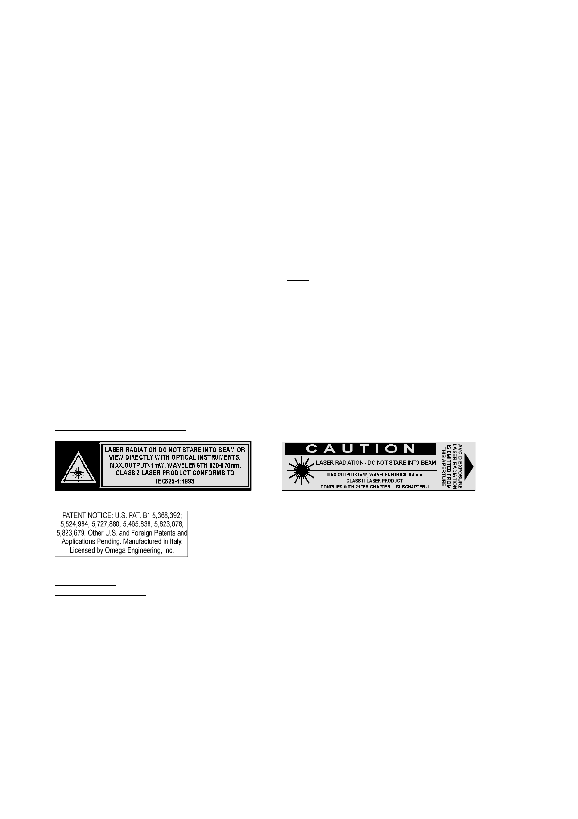
8.1 Laser Sight
You may receive harmful laser radiation exposure if you do not adhere to the warnings listed below:
USE OF CONTROLS OR ADJUSTMENTS OR PERFORMANCE OF PROCEDURES OTHER THAN THOSE
•
SPECIFIED HERE MAY RESULT IN HAZARDOUS RADIATION EXPOSURE.
• DO NOT LOOK AT THE LASER BEAM COMING OUT OF THE LENS OR VIEW DIRECTLY WITH OPTICAL
INSTRUMENTS – EYE DAMAGE CAN RESULT.
• USE EXTREME CAUTION WHEN OPERATING THE LASER.
• NEVER POINT THE LASER BEAM AT A PERSON.
• KEEP OUT OF REACH OF ALL CHILDREN.
CAUTION - LASER SAFETY
LASER RADIATION - DO NOT STARE INTO BEAM
CLASS 2 LASER PRODUCT CONFORMS TO IEC 823/93
CLASS II LASER PRODUCT COMPLIES WITH 21 CFR CHAPTER 1, SUBCHAPTER J.
W
AVELENGTH
: 630-670
– MAX.O
NM
UTPUT
: <1MW
WARNING
DO NOT ATTEMPT TO OPEN THE LASER SIGHT MODULE.
(T
HERE ARE NO USER-SERVICEABLE PARTS IN THE MODULE
).
8.2 Analogue input
Thermocouple input is optional for OSP series thermometers. The sensors are normally linked to electrical potentials
equal or near to the ground potential. However, in some applications, there may be present a common mode voltage to
ground. Check for voltage between input terminals and the ground, as this voltage can be transmitted to other devices
connected to the OSP series temperature indicator.
8.3 Danger and Certification Labels
The laser sight is standard in your thermometer. You can choose between different laser systems as described in section
1.1. Laser provides a visual indication of the field of view of the thermometer. The following figures show the parts and
the labels locations of the Laser sight module.
18
Page 19

19
Page 20

9 OPERATIONS
A
OSP series
portable infrared thermometers are factory calibrated before shipment.
During the start-up the operator should only select and load, if required, the pertinent application parameter as described
in the following paragraphs.
Before entering the procedure to operate the instrument it is useful the understanding of the messages that can be
present in the display.
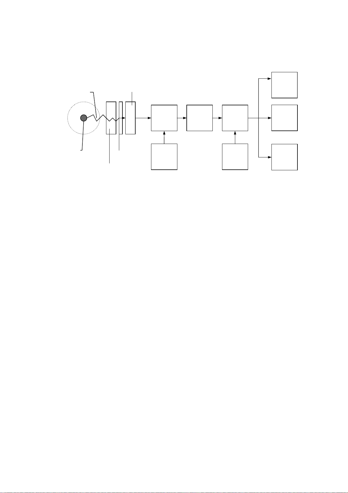
The following figure shows the overall layout of the display and an explanation of each symbol or message :
+-
HAL
4 7
°F
K
°C
LAL
5
6
8
9
10
11
1
15
13
14
12
2 3
Log Rcl Set
uto
Lock
e
Comp
1 - Indicates logging mode operative
2 - Enables recall of memory stored data
3 - Indicates the setting mode enabled during configuration and logging mode set up
4 - Low battery indication
5 - Temperature in degree Fahrenheit
6 - Temperature in degree Celsius
7 - Temperature in Kelvin
8 - Actual measured temperature value
9 - Indicates Low Alarm
10 - Indicates High Alarm
11 - Auxiliary measurement data or setting (AVG, LAL, HAL, MIN, MAX, DIF) or thermocouple input indication
12 - Operative emissivity value
13 - Ambient temperature compensation
14 - Continuous measurement mode
15 - Automatic acquisition in logging mode
The contact closure of the keys is acknowledged as a coded signal by the microprocessor that recognizes the operator’s
instructions.
<Trigger>
<
> <
▲▲▲▲
▼▼▼▼
>
Keep pressed for operation. Press twice, in sequence, to hold the instrument -ONValue setting or data selection during Configuration or Set-up procedures
<*> Laser sighting on/off or data acquisition mode set-up
MEM
<
> Data acquisition operation and logging manual step
SEL
<
> Selects the operative mode
ENTER
<
> Memory load key
9.1 Quick Start
To use the
Point the instrument at the object you want to measure and pull the trigger (the actual temperature value, the preprogrammed emissivity value and the auxiliary indication will be displayed); a “LOCK” symbol will appear on display.
Set emissivity value using the <▲> and <▼> keys. Refer to appendix A to define emissivity and for emissivity tables.
Press and release the trigger to switch the unit off.
OSP
infrared thermometer right away follow this simple steps :
9.2 How to Operate the instrument
To switch the instrument “On” keep the trigger pressed; when the trigger is released the instrument will be switched “Off”.
When continuous operations are required press twice, in sequence, the trigger to lock the operative mode.
The first display indication will show the type of instrument and the temperature technical unit enabled.
20
Page 21

°C
°C
°C
e
°C
e
e
°C
e
e
°C
e
followed, after few seconds, by one of the main operative display pages.
The displayed page will be the same as when the instrument was switched Off
°C
e
°C
e
°C
Lock
e
°C
°C
Lock
e
°C
°C
°C
ee
• Press the <
Lock
e
SEL
> key to select the required page.
Lock
e
Lock
e
• Press the <▲> and <▼> keys to adjust the emissivity value as required by the application.
9.3 Hold
To hold the measurement, press the <
°C
MEM
> key; the “X” symbol will be displayed on lower display.
ee
To run in continuous measurement, press the <
MEM
> key another time.
9.4 Laser sighting
C
AUTION: BEFORE USING THE LASER SIGHT READ THE RECOMMENDATIONS ON PARAGRAPH
21
15.2.2.
Page 22

In measuring mode, press the <*> key to enable (disable) the laser spot. After one second the message “LAS EN” (“LAS
DIS”) will be displayed.
When enabled, the laser can be turn on by pressing the <
Trigger
> button for more than 1 second; a flashing emission
indicator symbol “*” will appear on the lower display.
°C
ee
The laser will go out automatically releasing the <
NOTE: T
O PREVENT ANY COLLATERAL RADIATION IN EXCESS OF THE LIMITS DURING THE OPERATION OR MAINTENANCE, THE LASER
BEAM WILL AUTOMATICALLY SWITCHED OFF WHEN TRIGGER IS RELEASED
Trigger
> button.
(
ALSO IN LOCK OPERATION MODE
).
9.5 Unstable temperature measurement
When measuring a very unstable temperature process, is necessary a slow and stable reading.
advanced average mode that works with the following parameters :
Working band
!
Weight
!
The working band is used to define the maximum difference between the actual and previous measurement values
where average mode has to be operative. It means that if you are measuring ambient temperature ( for example 23°C )
and you point the instrument to the process ( for example 600°C ) you don’t need a slow increasing due to average ( The
difference is 600 – 23 = 577 °C ).
If working band is set at 100°C instrument don’t apply any average and it will pass directly to temperature of the process
( 600°C ) otherwise with standard average you will see the temperature slowly growing from ambient to the target point.
When instrument is measuring the process the difference due to unstable temperature is inside working band so it will
works in average mode.
More unstable is the process higher has to be the weight of the average. Higher is the weight ,slower will be the reading.
Weighted average effect
OSP
is equipped with an
Input temperature
fluctuations
Working band effect
Temperature
fluctuation
Indicated values with
weighted average = 0
Measured value with weighted
average=32 and working band
excluded
Indicated values with
weighted average = 2
To enable/disable the average mode follows the procedure below:
22
Indicated values with
weighted average= 32
Measured value with weighted
average=32 and working band
included
Page 23

" In measuring mode, press the <
°C
Sel
> key until the following page will appear:
ee
The display indicates the actual temperature value together with the technical unit symbol, the programmed
emissivity value and the averaged temperature value.
" At this stage press <
°C
ENTER
> key to enable the average mode. On the display will appear the following page:
e
The average mode is now enabled; the “X” symbol will appear. It will remain enabled after the instrument switching
off. To disable the average mode, repeat the above procedure. The “X” symbol will disappear. Average mode will
remain enabled also in data acquisition mode and in peak mode operations.
The standard programmed values on OSP are:
working band
=100°C and
average weight
=32 that are parameters
valid in most of your process applications.
To change the parameters setting, use the optional
Average
software for personal computer and TTL/RS232 cable.
9.6 Alarm settings
Low and High Alarm levels can be programmed and used in “hot spots” for fast scanning or long term surveillance.
To select these operative modes press, in sequence, the <
°C
SEL
> key to obtain the following display pages :
Lock
e
To change the Low and/or High Alarm settings follow the procedure indicated below :
• Press the <
ENTER
> key to enter the setting procedure. One digit of the setting line will blink. The blinking digit allows
a new adjustment.
• Press the <
SEL
> key to select a different digit or the polarity (+/-)
• Press <▲> and <▼> keys to modify the value of the blinking digit
• Repeat the last two steps to set the new alarm threshold
• Press the <
ENTER
> key to return to the normal operative mode with the new Low Alarm setting
If required the Low Alarm can be excluded setting the low alarm level above the full scale temperature value where the
message -Off- will appear.
23
Page 24

°C
e
• Press the <
SEL
> key to obtain the following page that enables the High Alarm setting
°C
HAL
e
• Repeat the setting procedure used for the low alarm setting
If required the High Alarm can be excluded setting the high alarm level above the full scale temperature value where the
message -Off- will appear.
°C
e
An alarm status, as shown in the above figure, will be announced to the operator by the -
HAL
- or -
LAL
-message on the
display and, simultaneously, by an acoustic signal.
• The acoustic signal can be acknowledged with the <
MEM
> key.
9.7 Thermocouple input
To select these operative modes press, in sequence, the <
°C
Lock
SEL
> key to obtain the following display pages :
e
• Press <▲> and <▼> keys to select the required type of thermocouple (type “S” or type “K”). This auxiliary input can
be used for contact temperature measurements or for automatic emissivity adjustments.
24
Page 25

°C
°C
Lock
e
• When selected the required type of thermocouple press the <
Lock
e
SEL
> key to obtain the following page showing
simultaneously both the actual IR temperature and the temperature measured with the thermocouple.
°C
Lock
e
If the measuring thermocouple is not connected or is broken, the display will indicate "Tc OTC".
°C
Lock
e
If the auxiliary input is disable, the display will indicate "Tc OFF".
°C
Lock
e
9.8 Minimum, maximum, average and difference indication
" Press the <
Minimum or Maximum value recorded in the interval time from the instrument switch -On- and the calculated
Difference value between the identified Maximum and Minimum values.
Lock
SEL
> key to obtain one of the following indications showing, in the auxiliary display, respectively the
°C
Lock
°C
Lock
°C
Lock
°C
e
e
When positioned on the max or min function, use <
e
ENTER
> key to reset the stored value.
25
e
Page 26

9.9 Automatic Emissivity Setting
This function is used to make an automatic setting of emissivity using an external thermocouple connected with the
auxiliary input.
• If necessary, enable the thermocouple input (see par. 9.2) and select the thermocouple type (see par. 8.6)
• Press the <▲> or <▼> key until the thermocouple temperature measure is displayed
°C
Lock
e
• Press <
and pyrometer. The emissivity will change automatically to the correct value by the OSP.
Lock
ENTER
> key for setting the emissivity value with reference to the temperature values read from thermocouple
°C
e
• An error message appear if the
the contact between the thermocouple and the object.
°C
Lock
OSP
measure a temperature highest of the thermocouple. If the error happen, verify
e
26
Page 27

10 CONFIGURATION
The operative configuration of the unit can be changed using the below indicated procedure.
• Switch the instrument -
• Keep the <
ENTER
Off
-
> key pressed and press the <
Trigger
> push button until the instrument displays the
indication relevant with the technical unit selection.
10.1 Technical Unit selection
the display will indicate one of the following technical units (Celsius, Fahrenheit and Kelvin):
Lock
Set
e
Lock
Set
e
Set
Lock
e
• Press the <▲> or <▼> key if you require to select a new technical unit
• Press the <
SEL
> key to select the new configuration step or press the <
Trigger
> to switch the instrument -Off-. The
new selection will be automatically memory stored.
10.2 Thermocouple input enabled
Press the <
SEL
> key until the following indication is displayed :
Set
°C
Lock
e
Lock
Set
e
°C
or
• Press the <▲> or <▼> key to enable (or to disable) the thermocouple auxiliary input operation.
• Press the <
SEL
> key to select the new configuration step or press the <
Trigger>
to switch the instrument -Off-. The
new selection will be automatically memory stored.
10.3 Temperature Scale selection
Set
SEL
> key until one of the following indication is displayed :
°C
Set
°C
Lock
Press the <
Lock
e
or
e
• Press the <▲> or <▼> key to select the required International Temperature Scale.
27
Page 28

• Press the <
SEL
> key to select the new configuration step or press the <
The new selection will be automatically memory stored.
10.4 Date & Real Time clock setting
The two following pages allow respectively date and real time updating .
Trigger>
key to switch the instrument -Off-.
Set
SEL
> key to display the date page
°C
• Press the <
Lock
e
Set
ENTER
SEL
ENTER
SEL
> key to enable the adjustment
> key to select the parameter to be modified (day, month, year)
> key to acknowledge the new setting
> key to enter the real time clock page
°C
• Press the <
• Press the <
• Press the <▲> or <▼> key to modify the selected parameter (blinking)
• Press the <
• Press the <
Lock
e
• Press the <
• Press the <
ENTER
SEL
> key to enable the adjustment
> key to select the parameter to be modified (hour, minute, second)
• Press the <▲> or <▼> key to modify the selected parameter
• Press the <
• Press the <
ENTER
> key to acknowledge the new setting
SEL
> key to select the new configuration step or press the <
Trigger
> to switch the instrument -Off-. The
new selections will be automatically memory stored.
10.5 Acquisition settings
• Press the <
Set
SEL
> key until the following indication is displayed :
°C
e
• Press <
• Press the <▲> or <▼> key to select the required setting: MAN, MIN, MAX or interval time for automatic acquisition ;
N
OTE
ENTER
: MAN
. MAX (MIN)
KEY
PRESSING THE
> for setting the acquisition mode;
UAL MODE DISPLAYS THE REAL TIME TEMPERATURE VALUES AND PERMITS TO STORE THE VALUE PRESSING THE
ACQUISITION MODE DISPLAYS ONL Y THE MAXIMUM (MINIMUM) VALUE AND PERMITS TO STORE THE VALUE
<MEM>
KEY
.
<MEM>
• To change the interval time for automatic acquisition, press <
change its value.
• Press <
ENTER
> to store the new acquisition mode. See Cap. 11 for appropriate data acquisition operation.
28
SEL
> to change decade and the <▲> or <▼> key to
Page 29

10.6 Buzzer On/Off
If the Alarms option is installed, it is possible to switch the buzzer on or off. This page allows the set-up of the acoustic
signal.
Lock
Set
e
°C
Set
°C
Lock
e
When the “Buzzer” is switched -Off- the alarm conditions will be announced only with the relevant message on the display.
10.7 OSP 500/800 decimal point selection
N
OTE:THIS FEATURE WORKS ON
It is possible to display the temperature measured with a decimal digit.
The following procedure is used to enable the operating mode.
" Switch the instrument off.
" Keep pressed <*>+<
measurements will be displayed with the decimal digit.
Repeat the above procedure to disable the operating mode.
OSP 500
SEL
> keys and switch the unit on by pressing the <
OSP800
OR
WITH FIRMWARE FROM VERSION
4.001.
Trigger
> key. The temperature
HAL
- or -
LAL
-
10.8 Ambient Temperature Compensation (TAM)
This function is used to compensate the measure from the ambient temperature.
Targets which have low emissivity will reflect energy from their surrounding environments, which is going to add to their
own emitted energy. If the temperature of the surrounding environment is the same value as the internal temperature of
the unit, there is no need to consider this value as it is automatically and continually measured. However, in some
industrial situations the surrounding environment (machines, furnaces, or other heat sources) has a much higher value
than the one of the internal of the unit temperature. The table below "
on measurement accuracy, with and without the use of the Ambient Temperature Compensation mode.
The Ambient Temperature Compensation mode should be used whenever the stated following points are true :
1. The target has a low emissivity.
2. Temperatures of objects facing targets are much hotter than the temperature of the unit.
3. An increased measurement accuracy is required
Actual Target
Emissivity Ambient Temp. Indicated Temp.
Temp.
°C °F °C °F °C °F °C °F
100 200 0.8 25 80 100 200 100 200
100 200 0.8 40 100 102 203 100 200
100 200 0.8 150 300 120 250 100 200
100 200 0.6 150 300 160 321 100 200
: The internal temperature of IR thermometer is assumed to be 25 °C (80 °F)
Note
Effect of TAM on Accuracy
Indicated Temp.
w/o TAM
" underlines these effects
w/ TAM
• Press the <
SEL
> key until one of the following indications is displayed :
29
Page 30

Set
°C
Set
°C
e
e
• Press the <▲> or <▼> key to enable (or to disable) the thermocouple auxiliary input operation.
Set
°C
e
• With the compensation function activated, press <
ambient temperature average value. Point
OSP
over those items and acquiring corresponding temperature values. A counter (from 1 to 255) indicates the number of
OSP
measurements considered (
displays the first value read during this procedure). These acquisitions have to be
done with emissivity ε=1, hence when acquisition starts the emissivity value has set automatically to one.
• Press <
the last acquired temperature value).
ENTER
> to stop acquisition and to confirm the read ambient temperature (at this moment
• Press the <
selections will be automatically memory stored.
To execute the temperature measurements with TAM, switch
SEL
> key to select the new configuration step or press <
ENTER
> to begin the measurements in order to calculate the
towards objects and surfaces surrounding the target, making a scan
OSP
will display
Trigger
OSP
on and set the emissivity to the correct target value.
> to switch the instrument off. The new
10.9 Firmware revision number
• Press the <
Set
Lock
e
The above page indicates the version of the firmware installed in your instrument.
This information is extremely important in all inquires for technical assistance support.
SEL
> key until the following page is displayed :
°C
10.10 Instrument serial number
• Press the <
Set
Lock
SEL
> key until the following page is displayed :
°C
e
The above page indicates the serial number of the instrument. Such number is extremely important for any request of
technical assistance support.
30
Page 31

10.11 Battery level of charge
• Press the <
Lock
e
SEL
> key until the following page is displayed :
Set
°C
Lock
+-
Set
e
°C
Set
°C
Lock
e
The above pages indicate the status of power supply and the level of charge of the battery.
When a voltage lower than 4.6V is present a low battery symbol is also displayed.
If the instrument is connected to the main line for battery charge or long term continuous operation a symbol “AC” will be
displayed instead of the battery voltage value.
31
Page 32

11 DATA ACQUISITION OPERATIVE MODE
When the optional accessory of the instrument is specified (Internal data memory + RS232 adapter + LogMan software)
the instrument is equipped with an internal memory to store up to 500 input data records. Two types of data acquisitions
can be selected by the user.
Continuous acquisition
The operator can manually, step by step, store his data through the keyboard or can select the interval time between
each acquisition and store progressively the input data in the “Tag 0” file.
Acquisition by dedicated Tags
Standard Agencies and Quality Auditors require the collection, organization and availability of traceability documents. A
supporting software is available to transfer a selection of plant inspections from a PC to the internal memory of the
instrument in order to simplify field check and select the appropriate Tag number. Dedicated input data are memory
stored and downloaded into a PC to document the inspection activity. Data can be saved on disks, viewed and printed in
a numeric or graphic mode.
A full description of this acquisition mode is available with the dedicated software.
To operate in continuous acquisition mode, refer to the following procedure.
11.1 How to operate in data acquisition mode
• Start this procedure with the instrument switched -Off-
• Keep the <
MEM
> key pressed and, simultaneously, press the <
Trigger
> until the following indication is displayed :
Log
Lock
°C
e
• Press the <▲> or <▼> key to select the required Tag identification code (Tag 0 or one out of the 20 available Tags
from "A" to "S"). Parameters (emissivity, low and high alarm settings) can be set through keyboard only in Tag 0.
Other Tags are reserved to operation through the dedicated PC software.
Log
Lock
e
• Press the <
Log
SEL
Log
°C
Lock
e
°C
> key to display the number of memory locations still available (500 indicates a full empty memory).
°C
Lock
e
Data can be recorded in the selected Tag in manual or automatic mode. Manual acquisition mode can be selected
between normal (MAN), MAX or MIN. About acquisition mode and setting of time acquisition, refer to par. 9.5.
32
Page 33

• Press the <
If automatic acquisition mode is set,
If MANual mode is set, the real time temperature measurement is displayed; press the <
MEM
> key to start the acquisition.
OSP
acquires automatically with the programmed time interval.
MEM
displayed value.
If MAX or MIN mode is set, the maximum (minimum) temperature measurement is displayed; press the <
to trigger acquisition and the <
ENTER
> key to reset the value for the next acquisition.
> key to store the
MEM
> key
• Press the <
Log
Lock
e
• Press the <
Log
Lock
e
• Press the <
Log
SEL
> key to obtain the page that allows the clearing of the memory stored data :
°C
ENTER
ENTER
> key to clear the memory content and to obtain the following message that require confirmation :
°C
> key to confirm the cancellation request and to obtain the following message :
°C
Lock
e
• Press the <
Tag (zzzzzzz = Furn686 = Trap888). The identification code is selectable only through software.
Log
Lock
SEL
> key to obtain the following page indicating the identification code (or name) assigned to the active
°C
e
• Press the <
SEL
> key to review the pages relevant with -
the data acquisition mode see the paragraph 10.2.
HAL
- and -
LAL
- alarm settings. To modify the alarm level in
33
Page 34

Log
Log
°C
Log
°C
°C
Lock
e
Lock
e
Lock
e
11.2 Recall stored data
OSP
°C
°C
thermometer.
SEL
> key, press the <
Log
Trigger
°C
> key to obtain the following indication :
• Switch off the
• Keeping pressed the <
Log
Lock
e
• Press the <▲> or <▼> key to select the required Tag identification code (Tag 0 or one out of the 20 available Tags
from "A" to "S").
Log
Lock
e
• Press the <
Log
Lock
SEL
Lock
e
> key to display the value of the first memory location in the selected Tag.
°C
e
• Press the <▲> or <▼> key to display the subsequent memory locations.
34
Page 35

12 LOGGING DATA MANAGER
LogMan software allows
‘Tag’.
This software also allows to download data from Instrument on document (table) with date, time and value. You can view
table, save table, print table, export table in excel-txt-html and obtain graphs. You can also manage data coping, moving
on other tables.
The software menages two different files :
" Extension .LMM are models. It means you will save on disk only preference setting.
" Extension .LMD are models and contains also data. It means you will save on disk current model with all data
on table.
When you open a new file a DEFAULT.LMM model will be automatically loaded.
If you prefer different preferences (for example header and footer with your company name)
load model DEFAULT.LMD change data and save it.
OSP series
users to set and prepare infrared thermometers to acquire the data organized by
12.1 Installation
LogMan
hard disk, color monitor and a Microsoft mouse or a compatible one.
In order to install
• Place the
• From the Windows Program Manager's File Menu, select
• Enter the filename A:setup.exe (substitute the letter A for the disk drive that contains
• Follow on screen instructions making sure to provide your
Once installed, in “Start” menu, the
runs on IBM PC under WINDOWS95 or NT. Minimum requirements are a 486 CPU with 8 Mb Ram and 2Mb on
LogMan
LogMan
for Windows, follow the below procedure:
disk in a 3.5" diskette drive;
LogMan
icon will appear it will be possible to boot it by select it as usual.
<RUN>
LogMan
;
LogMan
directory, when prompted, with the correct path.
diskette)
12.2 Program Architecture
LogMan
name, or on the icon which represents the action the user wants to carry out.
has a typical Windows structure with a series of menu and toolbars that can be recalled by clicking on the
The main menu program is structured as it follows:
35
Page 36

These menu are subdivided in:
File
New
Open
Options
Exit
Help
Index
About
When a document is loaded or created, the new main menu is:
File
New
Open
Save
Save As
Export
Close
Print setup
Print
Options
Language
Port settings
Synchronize instrument
Exit
New, Open, Save, Print menu.
Creates a new document.
Opens an existing document.
Set Communication port, text language and synchronize clock
Exits from Logman.
Help menu.
Offers you an index about topics on which you can get help.
Displays the version number of this application.
New, Open, Save, Print menu.
Creates a new document.
Opens an existing document.
Saves an opened document using the same file name.
Saves an opened document to a specified file name.
Exports opened documents as Excel, txt or HTML file
Closes an opened document.
Selects a printer and printer connection.
Prints a document.
Set Communication port, text language and synchronize clock
Selects language text
Select communication port COM
Sets IR thermometer internal clock equal to Computer
Exits from Logman.
Data
Edit
Window
Help
AutoLoad tag
Load tag
Save tag
Save as tag 0
Delete tag
Clear all tags
PC Log
Sample now
Preferences
Copy into new file
Copy into open file
Move into new file
Move into open file
Delete
Subtract
Tile
Cascade
Arrange Icons
Index
About
Instrument operation menu (Menu accessible only if ‘Data Table Window’ is active).
Loads automatically from the instrument.
Loads from the instrument.
Saves preferences on the instrument.
Saves preferences on the instrument Tag 0.
Deletes the Tag on the instrument.
Deletes all Tag on the instrument.
Logs data from the instrument.
Logs one datum only from the instrument.
Set preferences.
Data operation menu (Menu accessible only if ‘Data Table Window’ is active).
Copies a selection in to a new file.
Copies a selection in to an existing file.
Moves a selection in a new file.
Moves a selection in an existing file.
Deletes selections.
Subtracts two selections in a new file.
Windows operation menu.
Tiles all active windows.
Cascades all active windows.
Arranges all active icons.
Help menu.
Offers you an index to topics on which you can get help.
Displays the version number of this application.
36
Page 37

12.2.1 Toolbars
Additional tool bars menu appear when the data view window or the graph view window is selected.
Fig. 11.2a: Data view toolbar
Fig. 11.2b: Graph view toolbar
The following buttons are displayed on the toolbars.
View graph on actual data window
Pressing this button a new window, containing the graph of the active data table, is displayed.
Preference dialog
On preferences menu command you can set :
Instrument
- Tag name ( max 7 characters ).
- Emissivity ( from 0.10 to 1.00 ).
- Temperature scale ( IPTS 68 or ITS90 )
- Units ( °C, °F or K ).
- Decimal point ( 1 or 0.1 ).
- Alarms value and check box ( on/off ).
- Sampling time and total time of PC log.
Header
Footer
Print
- Top, header, left, right, bottom and footer distance in inches.
- Enable/Disable Grid and color.
- Enable/Disable Center table horizontally
Graph
- Autoscale or Lower and Upper Limits.
Lines ( max 10 ).
Lines ( max 10 ).
Select decimal point
(0 or 1)
Select engineering units
Enable/Disable alarms
Copy into a new file
Use this command to copy selected data onto a new file.
This command is unavailable if there are no data currently selected.
( °C, °F or K ).
37
Page 38

Copy into an open file
Use this command to copy selected data onto an opened file.
It will appear a list of current opened files to be selected.
This command is unavailable if there are no data currently selected.
Move into a new file
Use this command to move selected data onto a new file.
This command is unavailable if there are no data currently selected.
Move into an open file
Use this command to move selected data onto an opened file.
It will appear a list of current opened files to be selected.
This command is unavailable if there are no data currently selected.
Set instrument Tag 0
Sample now
Connect the unit to communication port of the computer.
Press the <
Sample now
with current preferences
> command to log one datum on actual document.
12.3 Quick starting
This software allows to download data from Instrument on document ( table ) with date, time and value.
You can view table, save table, print table, export table in excel-txt-html and obtain graph.
For example if you want to measure the temperature of the transformer model AGC 134.
" Run the command <
File New>
from the menu. The following windows will appear:
" Select the command <
parameters you need: For example:
TAG name : AGC 134
Emissivity : 0.98
Low Alarm Level: +15 °C (you don’t need it so you can set it very low)
High Alarm Level: +30 °C.
Data
> from the menu and then the option <
38
Preference
>. Fill in preferences windows the
Page 39

" Select <OK> button to save the preference setting in the PC Memory.
g
" From the preference menu you can also set the header and footer line as you need for later printed report.
" Save model (Save as …) with extension .LMM.
" Now connect the instrument with the communication cable and turn it on.
" Open the file AGC.LMM (if previously closed ).
" Select the <
Data
> command from the menu and then the option <
Save Tag
>. Select for example Tag A and press
the <Ok> button.
" Disconnect the unit and go on the field to take same measurements (see also cap.10 to operate in an acquisition
mode).
" Start this procedure with the
" Keep the <
Log
Lock
MEM
> key pressed and, simultaneously, press the <
°C
OSP
switched -Off-
Trigger
> until the following indication is displayed :
e
• Press the <▲> or <▼> key to select the Tag A identification code.
Lo
Lock
e
• Press the <
Log
Lock
e
°C
SEL
> key to display the number of memory locations still available.
°C
Data can be recorded in the selected Tag in manual or automatic mode. About the acquisition mode and setting of time
acquisition, refer to par. 9.5.
• If necessary, press the <
SEL
> key to obtain the page that allows the clearing of the previous memory stored data in
the Tag A:
39
Page 40

Log
Lock
°C
e
°C
°C
ENTER
ENTER
> key to clear the memory content and to obtain the following message that require confirmation :
> key to confirm the cancellation request and to obtain the following message :
SEL
> key to obtain the following page indicating the identification code (or name) assigned to the active
• Press the <
Log
Lock
e
• Press the <
Log
Lock
e
• Press the <
Tag (i.e. ACG 134).
Log
Lock
• Press the <
°C
134
e
SEL
> key to review the pages relevant with -
the data acquisition mode see the paragraph 10.2.
HAL
- and -
LAL
- alarm settings. To modify the alarm level in
Log
Lock
e
" Press the <
Log
°C
Lock
MEM
°C
e
> key to acquire one measurement value.
" Once the acquisition completed, you can switch OSP off and go back to the computer. Reconnect the unit to the PC
and open the file AGC.LMM (if previously closed).
" Run the command <
Autolo a d T a g
> From the <
Data
> menu (the program will search inside the instrument tag AGC
134 and will download data).
" Press the button to display the data graph window containing the graph of the active data table.
40
Page 41

Now you can save data on disk using name with extension LMD (for example TODAY.LMM).
41
Page 42

13 OPTIONS & ACCESSORIES
13.1 Printer operations
" Connect a compatible printer to
°C
Lock
e
" Press the <
Lock
MEM
> key to obtain the following indication:
°C
e
" Press the <
Date : 18/02/98
Time : 14:44:02
Measure : 186 °C
ENT
> key to print the Date, Time and measured value as follows:
OSP
and switch the thermometer on.
13.2 Sighting telescope system
Item Q.ty Part n.° Description
1 2 EE010015 fastening screws for guide
2 1 EE280169 guide
3 2 EE280179 mounting rings
4 1 EE280181 telescope
5 1 EE280198 filter ring
6 1 EE360053 filter HT
7 1 EE370133 O-ring
Installation of the telescope :
1 Remove with a cut screwdriver the nut protection caps placed on the upper part of the instrument.
2 Place the guide on the upper part of the pyrometer, taking care of orientating it so that it leans entirely on the back of
the instrument.
3 Fasten the screws in order to make the guide integral with the pyrometer.
4 Place the mounting rings on the guide, in order to cling them to the side edges. Let each ring slide along the guide
until each catch is housed in the respective slot. Fasten firmly each fastening screw with a coin or a screwdriver.
5 Separate the upper and the lower half of each mounting ring by removing the two screws, using the enclosed
hexagonal wrench.
6 Put the telescope in the supporting framework formed by the lower halves of the mounting rings and place the
extremity with the widest diameter turned towards the target.
7 Rotate the telescope into the mounting rings, in order to bring the elevation adjustment (UP) high. Fasten the
screws, avoiding to make an excessive clamping.
Alignment of the telescope :
1 Make the pyrometer integral with a support.
42
Page 43

2 Remove the elevation and the windage adjustment caps.
3 Switch on the two pinpointing lasers and aim them to a target placed at a distance equal to the working distance.
4 The aiming must be carried out by keeping the eyepiece at a distance of about 80 cm from the eye.
5 Operating on the two adjustments (elevation and windage), place the center of the reticule in connection with the
center of the axis joining the two spot lasers. The minimum suggested working distance is 5 meters, shorter working
distance can cause alignment problems.
6 In this way the telescope is aligned to operate at the working distance; a variation in the working distance requires a
new alignment of the telescope.
Filter installation
1 Filter use is suggested in viewing targets with temperature higher than 1000°C
2 Install the filter ring on the front side of the telescope lightly pushing the component
CAUTION
NEVER LOOK AT THE SUN THROUGH THE TELESCOPE: THE CONCENTRATION OF STRONG SOLAR RAYS CAN CAUSE SERIOUS EYE
DAMAGE
NEVER LOOK AT TARGET WITH TEMPERATURE HIGHER THAN
C
ONCENTRATION OF STRONG VISIBLE
.
1000°C
- IR
WITHOUT THE TELESCOPE PROTECTION FILTER
RADIATION CAN CAUSE EYE DAMAGE
.
13.3 Red Point pinpointing system
Item Q.ty Part n.° Description
1 2 EE010015 fastening screws for the guide
2 1 EE280169 guide
3 1 EE280180 N°1
4 1 EE360055 filter for T > 1300°C
5 1 EE360057 filter for T from 1000 to 1300°C
6 1 EE370127 O-ring/O-ring
red point sight device
N°2 mounting rings
N°1 polarize filter
N°1 lens Hood extension
Installation of the sighting device :
1. Remove with a cut screwdriver the nut protection caps placed on the upper part of the instrument.
2. Place the guide on the upper part of the pyrometer, taking care of orientating it so that it leans entirely on the back of
the instrument.
3. Fasten the screws in order to make the guide integral with the pyrometer.
4. Place the mounting rings on the guide, in order to cling them to the side edges. Let each ring slide along the guide
until each catch is housed in the respective slot. Fasten firmly each fastening screw with a coin or a screwdriver.
5. Separate the upper and the lower half of each mounting ring by removing the two screws, using the enclosed
hexagonal wrench.
6. Put the sighting device in the supporting framework formed by the lower halves of the mounting rings, so that the
rheostat hand grip is situated on the left side of the pyrometer, with respect to the aiming direction.
7. Rotate the sighting device into the mounting rings, in order to bring the elevation adjustment (UP) high. Fasten the
screws, avoiding to make an excessive clamping.
Alignment of the sighting device :
1. Make the pyrometer integral with a support.
2. Activate the illuminated red point by turning the rheostat hand grip clockwise to increase the brightness or in an
counter-clockwise direction to reduce it. The position “1” indicates the minimum brightness and the position “7”, the
maximum one.
3. The aiming must be carried out by keeping the eyepiece at a distance of at least 7 cm from the eye.
4. Remove the elevation and the windage adjustment caps.
5. Switch on the two pinpointing lasers and aim them to a target placed at a distance equal to the working distance.
The minimum suggested working distance is 5 meters, shorter working distances can cause alignment problems
6. Operating on the two adjustments (elevation and windage), place the illuminated red dot in connection with the
centre of the axis joining the two spot lasers.
7. In this way the sighting device is aligned to operate at the working distance ; a variation in the working distance
requires a new alignment of the sighting device.
Filter installation
1 Select the filter depending on the working temperature
2 Insert the selected filter in the internal side of the polarized filter mount
3 Place the O-ring over the filter to lock it
43
Page 44

4 Screw up the polarized filter with the inserted optical filter placed on the front side of the sighting device
CAUTION
IF Y
OUR
OSP
UNIT IS EQUIPPED WITH TELESCOPE OR "RED POINT" PINPOINTING SYSTEM, NEVER AIM
EYE DAMAGE COULD RESULT
.
OSP
DIRECTLY AT THE SUN, AS
44
Page 45

14 APPLICATION NOTES
14.1 Infrared energy
Each body, at temperatures above the absolute zero (-273°C or 0K), emits energy in the form of electromagnetic
radiation.
As the temperature of the body rises, the intensity of this infrared energy increases.
The temperature of this particular body can therefore be determined by measuring the intensity of this infrared energy.
An equipment used to measure the temperature with this method is called "infrared thermometer" or a "non-contact
thermometer" since the thermometer is not required to be in contact with the body in order to measure its temperature.
14.2 Applications
The temperature measurement of liquids or gases is well accomplished using a thermoelectric sensor thanks to the good
thermal exchange between the sensor and the fluid.
When solid objects are to be measured it is difficult to obtain a good thermal exchange and the possibility of making an
additional error should be kept into consideration.
Temperature measurements with direct contact are often impossible to be carried out when the target is moving or is
connected to dangerous electrical sources or when, for any other reason, it is impossible or difficult to touch it.
14.3 Emissivity
The infrared energy emitted by a body differs according to the composition of the body and to the physical condition of
the surface.
Non-contact thermometers are calibrated using a blackbody source (made with material that absorbs energy at all
wavelengths) as a reference standard.
However, to obtain the reading of the true temperature, it is necessary to compensate the thermometer for the actual
emissivity of the object to be measured.
Emissivity = Surface Radiation
Blackbody Radiation
OSP
All
The emissivity values relevant to different materials and surface conditions are detailed in “How to determine an object
emissivity” in Appendix A2 of this manual.
The values from the above tables are reference values only: emissivity can in fact be slightly higher with a higher
oxidation of the material .
infrared thermometers are equipped with an emissivity adjustment from 0.10 to 1.00.
14.4 Reflected energy compensation
The radiation perceived from the thermometer is the one emitted by the target plus the radiation reflected by the surface
of the object itself.
To obtain more accurate readings, particularly for measurements of low emissivity temperature objects, the energy
reflected from the target should be considered; that energy changes according to the temperature of the surrounding
environment.
A typical example of that principle of operation comes from re-heating furnaces, where the temperature of the vault is
considerably higher than the target temperature.
OSP
thermometers provide an auxiliary function "TAM" to compensate for the ambient temperature.
When the average value of the ambient temperature is set, the microprocessor processes a correction algorithm and
then displays the real temperature value of the target (see par. 9.7).
As an example, the error occurring when no auxiliary function "TAM", to compensate for the ambient temperature, is
enabled can reach 20°C when measuring a target at 100°C with the ambient temperature of 150°C.
45
Page 46

15 DIGITAL INTERFACE
OSP
The
The interface circuit is essentially based on the serial communication interface subsystem (SCI) on the chip of the
microcontroller. The output voltage levels are TTL at 0 to +5 V.
An optional adapter to convert the voltage level from 0 to +5 V to RS232 standard levels can be supplied. This adapter is
required to interface
15.1 Digital output wiring practice
The wiring to digital output signals is made through a mini DIN connector mounted on the lower end of the case.
The pertinent connections are indicated below :
portable IR thermometer can be equipped with a digital interface.
OSP
with a Personal Computer.
Rx IRtec P
Tx IRtec P
Analog Output
5 V
Female miniDIN connector
(case mounted - external view)
Dig. ground
Anal. ground
For easy interconnections a miniDIN connector with cable (cat. EE420123) can be supplied on request.
The color codes of the conductors can change with different suppliers; please check before using.
4 5 6
8
7
Front view
3
1 2
LINDY CINCH
pin 1 : brown black
pin 2 : red green
pin 3 : green blue
pin 4 : gray gray
pin 5 : purple yellow
pin 6 : blue white
pin 7 : orange red
pin 8 : yellow brown
15.2 TTL to RS 232 adapter
The cat. BB530001 TTL to RS232 adapter consists of a cable to which are connected a male mini DIN connector (for
OSP
) and a DB25 connector, that contains the electrical circuitry (for the PC).
The basic circuit and connections are as follows:
46
Page 47

+ 5 V
10 µF, 16 V
10 µF, 16 V
Tx
Rx
10 µF, 16 V
10 µF, 16 V
+
+
+
+
6
2 16 10
11
12
ICL 232
TSC 232
1
3
4
5
15
8
10 µF, 16 V
Rx
Tx
Ground
IBM
IBM
14
13
15.3 Communication protocol
IBM
+ 5 V
Tx
Rx
Mini-Din
TTL to RS 232 converter
IBM - PC
D
B
2
5
3
2
7
The exchange of information when a
OSP
is interconnected with a PC is as it follows.
Serial Interface of PC has to be set to 9600 Baud, 8 bit and No parity.
15.3.1 Computer data request from OSP to PC
Computer OSP
Tx IDNAME → Rx IDNAME Proceed if the name is acknowledged
Rx IDNAME ← Tx IDNAME If not, do not answer
Tx Instruction → Rx Instruction
Rx Instruction ← Tx Instruction
Tx char → Rx char
Rx DATA 1 ← Tx DATA 1
Tx char → Rx char
Rx DATA 2 ← Tx DATA 2
Tx char → Rx char
Rx DATA 3 ← Tx DATA 3
Tx char → Rx char
Rx DATA 4 ← Tx DATA 4
Tx CHKSUM → Rx char
Rx CHKSUM ← Tx CHKSUM
IDNAME, Instruction, DATA 1, DATA 2, DATA 3, DATA 4 and CHKSUM are 8-bit values (1 byte)
Tx CHKSUM = DATA 1+DATA 2+DATA 3+DATA 4 .AND. FF
Rx CHKSUM = DATA 1+DATA 2+DATA 3+DATA 4 .AND. FF
The above is useful to verify correct received data.
The minimum time-out of OSP is 3 seconds.
IDNAME is set to 1.
47
Page 48

Reading values
$00 - Pyrometer measure -------------------------------------------------------------- RX
DATA1 STATUS
DATA2 DATA3 VALUE (H)
DATA4 VALUE (L)
IF STATUS=0 MEASURE = SIGNED INTEGER ( VALUE ) / 10
IF STATUS=2 MEASURE = ERROR RJ
IF STATUS=10 MEASURE = OFL
IF STATUS=11 MEASURE = UFL
$01 - Emissivity---------------------------------------------------------------------------- RX
DATA1 DATA2 DATA3 DATA4 VALUE
EMISSIVITY = VALUE / 100
$03 - Max input value -------------------------------------------------------------------- RX
DATA1 DATA2 DATA3 VALUE (H)
DATA4 VALUE (L)
MAX = SIGNED INTEGER ( VALUE ) / 10
$04 - Min input value--------------------------------------------------------------------- RX
DATA1 DATA2 DATA3 VALUE (H)
DATA4 VALUE (L)
MIN = SIGNED INTEGER ( VALUE ) / 10
$05 - Average input value-------------------------------------------------------------- RX
DATA1 DATA2 DATA3 VALUE (H)
DATA4 VALUE (L)
AVERAGE = SIGNED INTEGER ( VALUE ) / 10
$06 - Tag ID,Eng.unit,Tc type,IPTS ------------------------------------------------- RX
DATA1 Tag ID (0=Tag0, 1=TagA, 2=TagB,.....,19=TagS)
DATA2 Eng.unit (1=°C - 2=K - 3=°F)
DATA3 Tc type (0=Tc K - 1=Tc S)
DATA4 IPTS (0=68 - 1=90)
$07 - Tc measure-------------------------------------------------------------------------- RX
DATA1 STATUS
DATA2 DATA3 VALUE (H)
DATA4 VALUE (L)
IF STATUS=0 MEASURE = SIGNED INTEGER ( VALUE ) / 10
IF STATUS=1 MEASURE = ERROR RJ
IF STATUS=2 MEASURE = TC OFF
IF STATUS=10 MEASURE = OPTC
$08 - HAL Setpoint------------------------------------------------------------------------ RX
DATA1 DATA2 DATA3 VALUE (H)
DATA4 VALUE (L)
HAL = SIGNED INTEGER ( VALUE )
IF HAL=3001 THEN HAL=OFF
$09 - LAL Setpoint------------------------------------------------------------------------ RX
DATA1 DATA2 DATA3 VALUE (H)
DATA4 VALUE (L)
LAL = SIGNED INTEGER ( VALUE )
IF LAL=3001 THEN LAL=OFF
$0B - First 4 chars tag description-------------------------------------------------- RX
DATA1 'X' (ASCII CODE)
DATA2 'X' (ASCII CODE)
DATA3 'X' (ASCII CODE)
48
Page 49

DATA4 'X' (ASCII CODE)
$0C - Last 4 chars tag description-------------------------------------------------- RX
DATA1 'X' (ASCII CODE)
DATA2 'X' (ASCII CODE)
DATA3 'X' (ASCII CODE)
DATA4 -
$0D - Alarm status------------------------------------------------------------------------ RX
DATA1 LAL Status (0=No alarm - 1=Alarm active)
DATA1 HAL Status (0=No alarm - 1=Alarm active)
DATA1 DATA1 -
$1C - Firmware version ----------------------------------------------------------------- RX
DATA1 'X' (ASCII CODE)
DATA2 'X' (ASCII CODE)
DATA3 'X' (ASCII CODE)
DATA4 'X' (ASCII CODE)
15.3.2 Computer data setting from PC to OSP
Computer OSP
Tx IDNAME → Rx IDNAME Proceed if the name is acknowledged
Rx IDNAME ← Tx IDNAME If not, do not answer
Tx Instruction → Rx Instruction
Rx Instruction ← Tx Instruction
Tx DATA 1 → Rx DATA 1
Rx char ← Tx char
Tx DATA 2 → Rx DATA 2
Rx char ← Tx char
Tx DATA 3 → Rx DATA 3
Rx char ← Tx char
Tx DATA 4 → Rx DATA 4
Rx char ← Tx char
Tx CHKSUM → Rx char
Rx char ← Tx char
IDNAME, Instruction, DATA 1, DATA 2, DATA 3, DATA 4 and CHKSUM are 8-bit values (1 byte).
CHKSUM = DATA 1+DATA 2+DATA 3+DATA 4 .AND. FF
The above is useful to verify correct received data.
The minimum time-out of
OSP
is 3 seconds.
IDNAME is set to 1.
Writing values
$80 - Emissivity---------------------------------------------------------------------------- TX
DATA1 0
DATA2 0
DATA3 0
DATA4 VALUE
VALUE = EMISSIVITY X 100
$82 - Tc type -------------------------------------------------------------------------------- TX
DATA1 0
DATA2 Tc type (0=Tc K - 1=Tc S)
DATA3 0
DATA4 0
$84 - HAL Setpoint------------------------------------------------------------------------ TX
DATA1 VALUE (HH)
DATA2 VALUE (H)
DATA3 VALUE (L)
49
Page 50

DATA4 VALUE (LL)
SIGNED LONG VALUE = ALARM HI
$85 - LAL Setpoint------------------------------------------------------------------------ TX
DATA1 VALUE (HH)
DATA2 VALUE (H)
DATA3 VALUE (L)
DATA4 VALUE (LL)
SIGNED LONG VALUE = ALARM LO
$86 - Tag ID selection-------------------------------------------------------------------- TX
DATA1 Tag ID (0=Tag0, 1=TagA, 2=TagB,.....,19=TagS)
DATA2 DATA3 DATA4 -
$87 - Tag description -------------------------------------------------------------------- TX
DATA1 Char position (0÷7)
DATA2 'X' (ASCII CODE)
DATA3 DATA4 -
15.3.3 Communication programs
In this paragraph are illustrated two examples of communication programs between the
OSP
and an IBM or IBM
compatible PC.
Example A:
Data transfer from OSP to PC
Connect
OSP
through adapter BB530001 (TTL-RS232 converter), to personal computer communication port COM1.
You will read temperature value.
Example B:
PC instructions to OSP
Connect
OSP
through adapter BB530001 (TTL-RS232 converter), to personal computer communication port COM1.
You will set emissivity to 0,80.
Example A
:
1Ø CHAR = Ø
2Ø IDNAME = 1
3Ø INSTRUCTION = 0
35 OPEN "COM1: 96ØØ, N,8,1,CD,CS,DS,RS" FOR RANDOM AS # 1
4Ø PRINT #1, CHR$ (IDNAME);:REM TRANSMIT IDNAME TO OSP
5Ø WHILE LOC (1) = Ø: WEND: REM WAIT RECEIVING IDNAME FROM OSP
6Ø IDNAME = ASC (INPUT$ (1, 1)): REM READ RECEIVED IDNAME FROM OSP
7Ø PRINT #1, CHR$ (INSTRUCTION);
8Ø WHILE LOC (1) = Ø: WEND
9Ø INSTRUCTION = ASC (INPUT$ (1, 1))
1ØØ PRINT #1, CHR$ (CHAR);
11Ø WHILE LOC (1) = Ø: WEND
12Ø DATA 1 = ASC (INPUT$ (1, 1))
13Ø PRINT #1, CHR$ (CHAR);
14Ø WHILE LOC (1) = Ø: WEND
15Ø DATA 2 = ASC (INPUT$ (1, 1))
16Ø PRINT #1, CHR$ (CHAR);
17Ø WHILE LOC (1) = Ø: WEND
18Ø DATA 3 = ASC (INPUT$ (1, 1))
19Ø PRINT #1, CHR$ (CHAR);
2ØØ WHILE LOC (1) = Ø: WEND
21Ø DATA 4 = ASC (INPUT$ (1, 1))
22Ø PRINT #1, CHR$ (CHAR);
231Ø WHILE LOC (1) = Ø: WEND
24Ø CHKSUM = ASC (INPUT$ (1, 1))
25Ø IF CHKSUM <> ((DATA1 + DATA2 + DATA3 + DATA4) AND &HFF) THEN PRINT "Error": END
26Ø VALUE = DATA3 * 256 + DATA4
27Ø IF VALUE > 32767 THEN VALUE =VALUE - 65536: REM 2'S COMPLEMENT
50
Page 51

28Ø PRINT "VALUE: " ; VALUE / 1Ø
29Ø END
Example B
1Ø CHAR = Ø
2Ø IDNAME = 1
3Ø INSTRUCTION = &H80
4Ø VALUE = 80
5Ø VALUE$ = HEX$ (VALUE/100)
55 WHILE LEN (VALUE$)<4: VALUE$ ="Ø"+VALUE$: WEND
6Ø IF LEN (VALUE$) > 4 THEN VALUE$ =RIGHT$ (VALUE$,4)
65 DATA1 = VAL ("&H" + LEFT$ (VALUE$, 2))
7Ø DATA2 = VAL ("&H" +RIGHT$ (VALUE$, 2))
75 DATA3 = Ø
8Ø DATA4 = Ø
9Ø CHKSUM = (DATA1 + DATA2 + DATA3 + DATA4) AND &H7F
1ØØ REM MEMORY RELEASE PREVIOUS 4.xx1 (Example 4.ØØØ, 4.2ØØ) MUST USE
11Ø REM NEXT LINE INSTEAD LINE 9Ø OR PROGRAM DOES'NT WORK
12Ø REM CHKSUM =(DATA1 + DATA2 + DATA3 + DATA4) AND &HFF
13Ø OPEN "COM1: 96ØØ,N,8,1,CD,CS,DS,RS" FOR RANDOM AS #1
14Ø PRINT #1, CHR$ (IDNAME) ; : REM TRANSMIT IDNAME TO OSP
15Ø WHILE LOC (1) = Ø: WEND: REM WAIT RECEIVING IDNAME FROM OSP
16Ø IDNAME = ASC (INPUT$ (1 , 1)): REM READ RECEIVED IDNAME FROM OSP
17Ø PRINT #1, CHR$ (INSTRUCTION) ;
18Ø WHILE LOC (1) = Ø : WEND
19Ø INSTRUCTION = ASC (INPUT$ (1 , 1))
2ØØ PRINT #1, CHR$ (DATA1) ;
21Ø WHILE LOC (1) = Ø : WEND
22Ø CHAR = ASC (INPUT$ (1 , 1))
23Ø PRINT #1, CHR$ (DATA2) ;
24Ø WHILE LOC (1) = Ø : WEND
25Ø CHAR = ASC (INPUT$ (1 , 1))
26Ø PRINT #1, CHR$ (DATA3) ;
27Ø WHILE LOC (1) = Ø : WEND
28Ø CHAR = ASC (INPUT$ (1 , 1))
29Ø PRINT #1, CHR$ (DATA4) ;
3ØØ WHILE LOC (1) = Ø : WEND
31Ø CHAR = ASC (INPUT$ (1 , 1))
32Ø PRINT #1, CHR$ (CHKSUM) ;
33Ø WHILE LOC (1) = Ø : WEND
34Ø CHAR = ASC (INPUT$ (1 , 1))
35Ø PRINT "Transmitted."
39Ø END
:
51
Page 52

16 MAINTENANCE
OSP
Each
The calibration should be verified and re-adjusted if the instrument shows an error exceeding the declared specifications
or when a critical active or passive component is replaced (either at the component level or at the board level).
OMEGA
16.1 Faulty operating conditions
During the start-up and measuring modes, faulty conditions of the instrument will be announced with coded messages.
If the faulty condition is critical for the application, it is recommended to re-start the pertinent set-up procedure.
All errors which cannot be recovered without the user's knowledge, result in some system action to inform the operator
via message and where possible to restore the system.
Restarting the instrument from -Power ON- may clear the error, but generally such messages are caused by hardware or
software faults, which require the user's action.
portable infrared thermometer has been factory tested and calibrated before shipment.
engineers will give prompt support for any request of assistance.
Display Error Type Solution
Err 1
Err 2
Err 3
OTC
RJer
Internal EEPROM memory error Contact technical support
IR sensor reading error Verify ambient temperature
(from -5 to +55°C)
Calibration data error Recalibrate unit
No sensor connected at Tc input Connect sensor
Cold-junction sensor reading error Verify ambient temperature
(from -5 to +55°C)
16.2 Storage
If the instrument has been left unused for a long time, it is recommended to remove the batteries.
Store the instrument in the original package, at a temperature from -30°C to +60°C, with R.H. less than 90%.
If the instrument has been unused for a month check the battery voltage, and charge the Ni-MH batteries for at least 12
hours with the unit switched off.
52
Page 53

APPENDIX
53
Page 54

A1 How to determine an object emissivity
Emissivity is the measure of an object ability to absorb, transmit, and emit infrared energy. It can have a value from 0
(shiny mirror) to 1.0 (blackbody). If a value of emissivity higher than the actual one is set, the output will read low,
provided that the target temperature is above the ambient one. For example, if 0.95 is set in and the actual emissivity is
0.9, the reading will be lower than the true temperature when the target temperature is above the ambient one.
The emissivity can be determined by one of the following methods, in order of preference:
1. Determine the actual temperature of the material using a sensor such as a RTD, thermocouple or another suitable
method. Next, measure the object temperature and adjust the emissivity setting until the correct value is reached.
This is the correct emissivity for the measured material.
2. For relatively low temperature objects (up to 260°C or 500°F, place a piece of tape, such as a masking, on the
object. Make sure the tape is large enough to cover the field of view. Next, measure the tape temperature using
an emissivity setting of 0.95. Finally, measure an adjacent area on the object and adjust the emissivity setting
until the same temperature is reached. This is the correct emissivity for the measured material.
3. If a portion of the surface of the object can be coated, use a flat black paint, which will have an emissivity of about
0.98. Next, measure the painted area using an emissivity setting of 0.98. Finally, measure an adjacent area on
the object and adjust the emissivity setting until the same temperature is reached. This is the correct emissivity for
the measured material.
A1.1 Typical Emissivity Values
The following table provides a brief reference guide to determine emissivity and can be used when one of the above
methods is not practical. Emissivity values shown in the table below are only approximate, since several parameters may
effect the emissivity of an object. These include the following ones:
1. Temperature
2. Angle of measurement
3. Geometry (plane, concave, convex, etc.)
4. Thickness
5. Surface quality (polished, rough, oxidized, sandblasted)
6. Spectral region of measurement
7. Transmissivity (i.e., thin film plastics)
54
Page 55

A1.2 Metals - Typical Emissivity Values
1.0 µm 1.6 µm 5.1 µm 8-14 µm
Aluminum
Non-Oxidized 0.1-0.2 0.02-0.2 0.02-0.2 0.02-0.1
Oxidized 0.4 0.4 0.2-0.4 0.2-0.4
Alloy A 3003
Oxidized — 0.4 0.4 0.3
Roughened 0.2-0.8 0.2-0.6 0.1-0.4 0.1-0.3
Polished 0.1-0.2 0.02-0.1 0.02-0.1 0.02-0.1
Brass
Polished 0.8-0.95 0.01-0.05 0.01-0.05 0.01-0.05
Burnished — — 0.3 0.3
Oxidized 0.6 0.6 0.5 0.5
Carbon
Non-oxidized 0.8-0.95 0.8-0.9 0.8-0.9 0.8-0.9
Graphite 0.8-0.9 0.8-0.9 0.7-0.9 0.7-0.8
Chromium 0.4 0.4 0.03-0.3 0.02-0.2
Copper
Polished 0.05 0.03 0.03 0-03
Roughened 0.05-0.2 0.05-0.2 0.05-0.15 0.05-0.1
Oxidized 0.2-0.8 0.2-0.9 0.5-0.8 0.4-0.8
Gold 0.3 0.01-0.1 0.01-0.1 0.01-0.1
Haynes Alloy 0.5-0.9 0.6-0.9 0.3-0.8 0.3-0.8
Inconel
Oxidized 0.4-0.9 0.6-0.9 0.6-0.9 0.7-0.95
Sandblasted 0.3-0.4 0.3-0.6 0.3-0.6 0.3-0.6
Electro-polished 0.2-0.5 0.25 0.15 0.15
Iron
Oxidized 0.4-0.8 0.5-0.9 0.6-0.9 0.5-0.9
Non-oxidized 0.35 0.1-0.3 0.05-0.25 0.05-0.2
Rusted — 0.6-0.9 0.5-0.8 0.5-0.7
Molten 0.35 0.4-0.6 — —
Iron Cast
Oxidized 0.7-0.9 0.7-0.9 0.65-0.95 0.6-0.95
Non-oxidized 0.35 0.3 0.25 0.2
Molten 0.35 0.3-0.4 0.2-0.3 0.2-0.3
Iron Wrought
Dull 0.9 0.9 0.9 0.9
Lead
Polished 0.35 0.05-0.2 0.05-0.2 0.05-0.1
Rough 0 65 0.6 0.4 0-4
Oxidized — 0.3-0.7 0.2-0.6 0.2-0.6
Magnesium 0.3-0.8 0.05-0.3 0.03-0.15 0.02-0.1
Mercury — 0.05-0.15 0.05-0.15 0.05-0.15
Molybdenum
Oxidized 0.5-0.9 0.4-0.9 0.3-0.7 0.2-0.6
Non-oxidized 0.25-0.35 0.1-0.3 0.1-0.15 0.1
Monel (Ni-Cu) 0.3 0.2-0.6 0.1-0.5 0.1-0.14
Nickel
Oxidized 0.8-0.9 0.4-0.7 0.3-0.6 0.2-0.5
Electrolytic 0.2-0.4 0.1-0.3 0.1-0.15 0.05-0.15
Platinum
Black — 0.95 0.9 0.9
Silver 0.04 0.02 0.02 0.02
Steel
Cold-Rolled 0.8-0.9 0.8-0.9 0.8-0.9 0.7-0.9
Ground Sheet — — 0.5-0.7 0.4-0.6
Polished Sheet 0.35 0.25 0.15 0.1
Molten 0.35 0.25-0.4 0.1-0.2 —
Oxidized 0.8-0.9 0.8-0.9 0.7-0.9 0.7-0.9
Stainless 0.35 0.2-0.9 0.15-0.8 0.1-0.8
Tin (Non-oxidized) 0.25 0.1-0.3 0.05 0.05
Titanium
Polished 0.5-0.75 0.3-0.5 0.1-0.3 0.05-0.2
Oxidized — 0.6-0.8 0.5-0.7 0.5-0.6
55
Page 56

1.0 µm 1.6 µm 5.1 µm 8-14 µm
Tungsten 0.1-0.6 0.05-0.5 0.03
Polished 0.35-0.4 0.1-0.3 0.05-0.25 0.03-0.1
Zinc
Oxidized 0.6 0.15 0.1 0.1
Polished 0.5 0.05 0.03 0.02
A1.3 Non-metals - Typical Emissivity Values
1.0 µm 1.6 µm 5.1 µm 8-14 µm
Asbestos 0.9 0.9 0.95 0.95
Asphalt — 0.95 0.95 0.95
Basalt — 0.7 0.7 0.7
Carborundum — 0.9 0.9 0.9
Ceramic 0.4 0.8-0.95 0.95 0.95
Clay — 0.8-0.95 0.95 0.95
Concrete 0.65 0.9 0.95 0.95
Cloth — 0.95 0 95 0.95
Glass
Plate — 0.98 0.85 0.85
“Gob” — 0.9 — —
Gravel — 0.95 0.95 0.95
Gypsum — 0.4-0.97 0.8-0.95 0.8-0.95
Ice — — 0.98 0.98
Limestone — 0.4-0.98 0.98 0.98
Paint — — 0.9-0.95 0.9-0.95
Paper (any color) — 0.95 0.95 0.95
Plastic (opaque, — 0.95 0.95 0.95
over 20 mils)
Rubber — 0.9 0.9 0 95
Sand — 0.9 0.9 0.9
Snow — 0.9 0.9 0.9
Soil — — 0.9-0.98 0.9-0.98
Water — — 0.93 0.93
Wood, Natural — 0.9-0.95 0.9-0.95 0.9-0.95
To optimize surface temperature measurements consider the following guidelines:
1. Determine the object emissivity using the suitable instrument for measurement.
2. Avoid reflections by shielding the object from surrounding high temperature sources.
3. For higher temperature objects use shorter wavelength instruments, whenever any overlap occurs.
4. For semi-transparent materials such as plastic films and glasses, assure that the background is uniform and lower in
temperature than the object.
5. Mount the sensor perpendicularly to the surface whenever the emissivity is less than 0.9. In any case, do not exceed
angles more than 30 degrees from incidence.
56
Page 57

INDEX
A
Acquisition by dedicated Tags; 32
Acquisition settings; 28
Alarm settings; 23
Ambient Temperature Compensation (TAM); 29
Analog Output; 10
Analogue input Warnings & Cautions; 18
APPLICATION NOTES; 45
Applications; 45
Automatic Emissivity Setting; 26
B
Battery charger; 14
Battery level of charge; 31
Buzzer On/Off; 29
C
Calculated Measurements; 11
Case; 11
Communication programs; 50
Communication protocol; 47
Computer data request from OSP to PC; 47
Computer data setting from PC to OSP; 49
CONFIGURATION; 27
Continuous acquisition; 32
D
Danger and Certification Labels; 18
DATA ACQUISITION OPERATIVE MODE; 32
Date & Real Time clock setting; 28
Decimal point selection; 29
Digital Inteface; 10
Digital interface; 14; 46
Digital output wiring practice; 46
Display; 10; 14
E
I
Infrared energy; 45
Instrument codes; 7
Instrument serial number; 30
INTRODUCTORY NOTE; 3
K
Keyboard; 10; 13
L
Laser Sight Warnings & Cautions; 18
Laser Sighting; 21
Logging Data Manager; 11
LOGGING DATA MANAGER; 35
Logging Mode; 11
LogMan
Program architecture; 35
LogMan
Installation; 35
Quick starting; 38
Toolbars; 37
M
MAINTENANCE; 52
Metals - Typical Emissivity Values; 55
Microcontroller; 14
Minimum, maximun and difference indication; 25
N
Non-metals - Typical Emissivity Values; 56
O
OPERATIONS; 20
Optical System; 9
OPTIONS & ACCESSORIES; 42
Emissivity; 45
F
Faulty operating conditions; 52
Firmware; 14
Firmware revision number; 30
FUNCTIONAL DESCRIPTION; 13
G
General; 9
GENERAL DESCRIPTION; 6
GENERAL FEATURES; 9
H
Hold; 21
How to determine an object emissivity; 54
How to maximize the life span of the battery; 17
How to operate in data acquisition mode; 32
How to Operate the instrument; 20
P
PHYSICAL DESCRIPTION; 12
Power supply; 13
POWER SUPPLY; 17
Power supply from main line; 17
Power supply with alkaline batteries; 17
PRE-OPERATIONAL CHECK; 16
Printer operations; 42
Q
Quick Start; 20
R
Recall stored data; 34
Rechargeable batteries; 17
Red Point pinpointing system; 43
Reflected energy compensation; 45
57
Page 58

S
S
AFETY WARNINGS
Self calibration; 10
Sighting telescope system; 42
Specifications; 8
Storage; 52
; 18
T
Thermocouple input; 24
Thermocouple Input; 10
Thermocouple input enabled; 27
TTL to RS 232 adaptor; 46
U
UNPACKING; 15
Unstable temperature measurement; 22
TABLE OF CONTENTS; 4
Taking measurements; 9
Target dimensions at different distances; 8
Target pinpointing; 9
Technical Unit selection; 27
Temperature Scale selection; 27
Warnings and Cautions; 18
Weight
Working band
; 22
; 22
W
58
Page 59

WARRANTY/DISCLAIMER
OMEGA ENGINEERING, INC. warrants this unit to be free of defects in materials and workmanship for a period of
months
year product warranty
from date of purchase. OMEGA Warranty adds an additional one (1) month grace period to the normal
to cover handling and shipping time. This ensures that OMEGA’s customers receive maximum
13
one (1)
coverage on each product.
If the unit should malfunction, it must be returned to the factory for evaluation. OMEGA’s Customer Service Department
will issue an Authorized Return (AR) number immediately upon phone or written request. Upon examination by OMEGA,
if the unit is found to be defective it will be repaired or replaced at no charge. OMEGA’s WARRANTY does not apply to
defects resulting from any action of the purchaser, including but not limited to mishandling, improper interfacing,
operation outside of design limits, improper repair, or unauthorized modification. This WARRANTY is VOID if the unit
shows evidence of having been tampered with or shows evidence of being damaged as a result of excessive corrosion;
or current, heat, moisture or vibration; improper specification; misapplication; misuse or other operating conditions
outside of OMEGA’s control. Components which wear are not warranted, including but not limited to contact points,
fuses, and triacs.
OMEGA is pleased to offer suggestions on the use of its various products However, OMEGA neither assumes
responsibility for any omissions or errors nor assumes liability for any damages that result from the use of its
products in accordance with information provided by OMEGA, either verbal or written. OMEGA warrants only
that the parts manufactured by it will be as specified and free of defects. OMEGA MAKES NO OTHER WARRANTIES OR REPRESENTATIONS OF ANY KIND WHATSOEVER, EXPRESSEO OR IMPUED, EXCEPT THAT OF
TITLE, AND ALL IMPLIED WARRANTlES INCLUDING ANY WARRANTY OF MERCHANTABIUTY AND RTNESS
FOR A PARTlCULAR PURPOSE ARE HEREBY DISCLAIMED. LIMITATlON OF LIABILITY: The remedies of
purchaser set forth herein ate exclusive and the total liability of OMEGA with respect to this order, whether
based on contract, warranty, negligence. Indemnification, strict liability or otherwise, shall not exceed the
purchase price of the component upon which liability is based. In no event shall OMEGA be liable for
consequential, incidental or special damages.
CONDITIONS: Equipment sold by OMEGA is not intended to be used, nor shall it be used: (1) as a ”Basic Component”
under 10 CFR 21 (NRC), used in or with any nuclear installation or activity; or (2) in medical applications or used on
humans. Should any Product(s) be used in or with any nuclear installation or activity, medical application, used on
humans, or misused in any way, OMEGA assumes no responsibility as set forth in our basic WARRANTY/DISCLAIMER
language, and additionally, purchaser will indemnify OMEGA and hold OMEGA harmless from any liability or damage
whatsoever arising out of the use of the Product(s) in such a manner.
RETURN REQUESTS / INQUIRIES
Direct all warranty and repair requests/inquiries to the OMEGA Customer Service Department. BEFORE RETURNING
ANY PRODUCT(S) TO OMEGA, PURCHASER MUST OBTAIN AN AUTHORIZED RETURN (AR) NUMBER FROM
OMEGA’S CUSTOMER SERVICE DEPARTMENT (IN ORDER TO AVOID PROCESSING DELAYS). The assigned AR
number should then be marked on the outside of the return package and on any correspondence.
The purchaser is responsible for shipping charges, freight, insurance and proper packaging to prevent breakage in
transit.
WARRANTY
FOR
RETURNS, please has the
following information available BEFORE contacting
OMEGA:
1. P.O. number under which the product was
PURCHASED,
2. Model and serial number of the product under
warranty, and
3. Repair instructions and/or specific problems
relative to the product.
OMEGA’s policy is to make running changes, not model changes, whenever an improvement is possible. This affords our customers the
latest in technology and engineering.
OMEGA is a registered trademark of OMEGA ENGINEERING, INC.
(C) Copyright 1999 OMEGA ENGINEERING, INC. All rights reserved. This document may not be copied, photocopied, reproduced,
translated, or reduced to any electronic medium or machine-readable form, in whole or in part, without prior written consent of OMEGA
ENGINEERING, INC.
PATENT NOTICE: U.S. PAT. B1 5,368,392; 5,524,984; 5,727,880; 5,465,838; 5,823,678; 5,823,678; 5,823,679. Other U.S. and
Foreign Patents and Applications Pending. Manufactured in Italy. Licensed by Omega Engineering Inc.
NON-WARRANTY
FOR
REPAIRS, consult OMEGA for
current repair charges. Have the following information
available BEFORE contacting OMEGA:
1. P.O. number to cover the COST of the repair,
2. Model and serial number of product, and
3. Repair instructions and/or specific problems relative to
the product.
59
Page 60

Where Do I Find Everything I Need for
Process Measurement and Control?
OMEGA…Of Course!
TEMPERATURE
!!!!
Thermocouple, RTD & Thermistor Probes, Connectors, Panels & Assemblies
!!!!
Wire: Thermocouple, RTD & Thermistor
!!!!
Calibrators & Ice Point References
!!!!
Recorders, Controllers & Process Monitors
!!!!
Infrared Pyrometers
PRESSURE, STRAIN AND FORCE
!!!!
Transducers & Strain Gauges
!!!!
Load Cells & Pressure Gauges
!!!!
Displacement Transducers
!!!!
Instrumentation & Accessories
FLOW/LEVEL
!!!!
Rotameters, Gas Mass Flowmeters & Flow Computers
!!!!
Air Velocity Indicators
!!!!
Turbine/Paddlewheel Systems
!!!!
Totalizers & Batch Controllers
pH/CONDUCTIVITY
!!!!
pH Electrodes, Testers & Accessories
!!!!
Benchtop/Laboratory Meters
!!!!
Controllers, Calibrators, Simulators & Pumps
!!!!
Industrial pH & Conductivity Equipment
DATA ACQUISITION
!!!!
Data Acquisition & Engineering Software
!!!!
Communications-Based Acquisition Systems
!!!!
Plug-in Cards for Apple, IBM & Compatibles
!!!!
Datalogging Systems
!!!!
Recorders, Printers & Plotters
HEATERS
!!!!
Heating Cable
!!!!
Cartridge & Strip Heaters
!!!!
Immersion & Band Heaters
!!!!
Flexibie Heaters
!!!!
Laboratory Heaters
ENVIRONMENTAL MONITORING AND CONTROL
!!!!
Metering & Control Instrumentation
!!!!
Refractometers
!!!!
Pumps & Tubing
!!!!
Air, Soil & Water Monitors
!!!!
Industrial Water & Wastewater Treatment
!!!!
pH, Conductivity & Dissolved Oxygen Instruments
M-3257/02
60
 Loading...