

Page 1
CAUTION!
is not intended for
or
use
I
use on human8
-
This product
medkd
L
Am
OME6.4
Teekmdoglea
http://www.omega.com
e-mail:
info@omega.com
lhquy
J
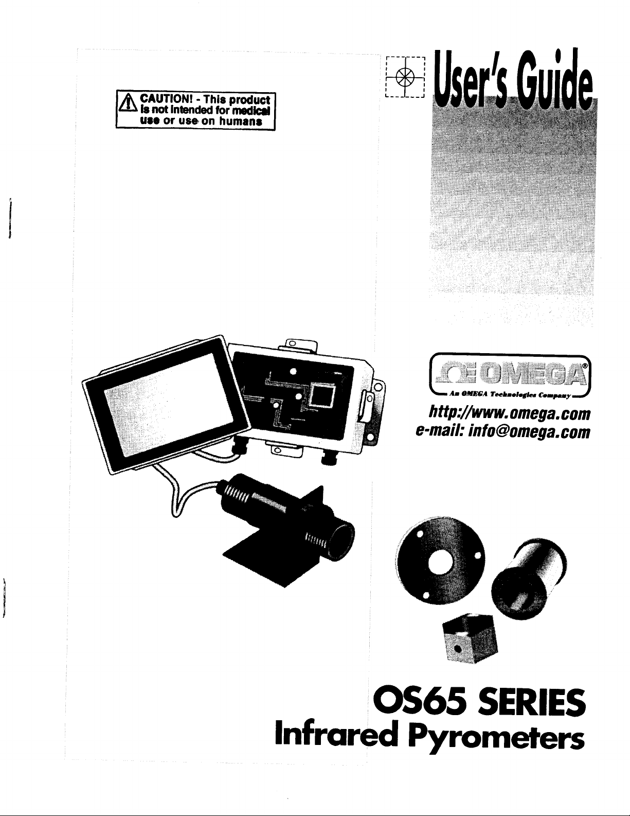
OS65 SERIES
Infrared Pyrometers
Page 2
OMEGAneP
On-Line Service
http://www.omega.com
Servicing North America:
Internet e-mail
info@omega.com
USA:
IS0
900 1
Certified
Canada:
For immediate technical or application assistance:
USA and Canada:
Mexico and
Latin America:
Benelux:
Czech Republic:
France:
Germany/Austria:
United Kingdom:
IS0
9002 Certified
One
Omega Drive, Box 4047
Stamford, CT 06907-0047
Tel: (203) 359-1660 FAX: (203) 359-7700
e-mail:
976
Lava1 (Quebec)
Tel: (514) 856-6928 FAX: (514) 856-6886
e-mail:
Sales Service: l-800-826-6342
Customer Service: l-800-622-2378
Engineering Service: l-800-872-9436
TELEX: 996404 EASYLINK: 62968934 CABLE: OMEGA
Tel: (95)
En Espariol: (203) 359-1660 ext: 2203
info@omega.com
Bergar
H7L
canada@omega.com
800-TC-OMEGASM
5Al
l-800-TC-OMEGA ’”
I
1-800-622-BEST’L”
/
l-800-USA-WHENSM
/
FAX: (95) 203-359-7807
e-mail:
espanol@mega.com
Servicing Europe:
Postbus
Tel: (31) 20 6418405
Toll Free in Benelux: 06 0993344
e-mail:
Ostravska 767,733 01 Karvina
Tel: 42 (69) 6311899
e-mail:
9, rue
Tel: (33) 130-621-400
Toll Free in France: 0800-4-06342
e-mail:
Daimlerstrasse 26, D-75392 Deckenpfronn, Germany
Tel: 49 (07056) 3017
Toll Free in Germany: 0130 11 2166
e-mail:
25 Swannington Road,
Broughton Astley, Leicestershire,
LE9
Tel: 44 (1455) 285520
FAX: 44 (1455) 283912
8034, 1180 LA Amstelveen, The Netherlands
FAX: (31) 20 6434643
nl@mega.com
FAX: 42 (69) 6311114
czech@mega.com
Papin,
Denis
france@@mega.com
germany@bmega.com
6TU, England
78190 Trappes
Toll Free in England: 0800-488-488
e-mail:
uk@?omega.com
FAX: (33) 130-699-120
FAX: 49 (07056) 8540
P.O. Box
Irlam, Manchester,
M44
Tel: 44 (161) 777-6611
FAX: 44 (161) 777-6622
7,
Omega Drive,
5EX,
England
It
is
the policy of OMEGA to comply with all worldwide safety and
apply. OMEGA is constantly pursuing certification of its products to the European New Approach
Directives. OMEGA will add the CE mark to every appropriate device upon certification.
The information contained in this document is believed to be correct but OMEGA Engineering, Inc. accepts
no liability for any errors it contains, and reserves the right to alter specifications without notice.
WARNING: These products are not designed for use in, and should not be used for, patient connected applications.
EMC/EMI regulations that
Page 3
Table of Contents
OS65 Series
section
Section 1: Introduction
1.1
General Description
1.2 Available Models
1.3 Accessories
Section 2:
2.1 Unpacking
2.2 Dimensions
23 Wiring
Section 3: Operation
3.1 Emissivity
3.2 Emissivity Adjustment
3.3 Emissivity Tables
3.4
Comparison
35
Maintenance
..................
Iustalhtion
..“...“m....“...“.“.......~-.“-..~..~....-..................-”-”..~....“..“~........”
..
..~.H.....“...“..~~~..~....~.~~..~........~”~...~~“~.~~...~..~........“.....”
.
..H.........................~“~.”..”..~.”.~..~...“...“~~.~””~..~.~~.....“..~.“......““..“..”
.“I.“.-“...“....“...““....~...“........~...”~.~..“........~..~.~..~...“~.“........“....~
Measurements
--...-.--...“..“.....~.....“.~~~.”
..~...................._._.....“....~......................”_.....“....~.“_.......”
.
..................
..-..-......HI.“ W..““.~““.-....“”.....-........-.““~.-“.....”..-.“-..”
..“...““.“..“-.....~..“...-......................~.“..--“”....-.-
..“.....“.“.~.~“.m.“....“.~..............~....”...““~~..~.....~.-..................”
..
..“w....m....................““.....”~...~.”.””....-“-“-“”-”-.....“....“...”
wt.......~.“.~.~...“~~.~....~.““~..~~..”.~...........~.....~..”....~”
..........
“.“.........UI.
..“.......~..~...~~...............”.......~.-.”~.~
“~“..“..N......“...~.~.....“..~.~....”..””.~-”.~.“.~..........”...”
~.UlltUll_U.“..“.”
-.
.
...
...-........U....
._.
..-.““- m-....=.....“......“.-“.“-.
O...-..
-
........
....................
..........
..........
.H..
“.._
....
-.
..
Page
1
1
1
2
2
..
2
3
..
4
.
6
6
.
6
..-
.
7
..
8
“oo.“”
8
Section 4: Specifications
4.1 Specifications
4.2 Field of View Diagrams
4.3 Accessories Dimensions
4.4
Digital Output
~“..“.H~.........“~..~“.~.~.~““..~..”~~...”..~...~“...~-.~”..~”.“~.~“”
Option
..~.......~........~....“..“~..“”~~....~.~”~...“.....“....~.....“.~..“.”
-.
.m........“..“..“...-~.~-..-..“.....””......~....“-..“-.-”.-”
......
“._“...___
...
“................“............
-.
U.“IH~.mm”...“ W..“-...~“..““..““.-
...
.
--.-“UIIIIIIII
S.““.rm...rn
.
..m....
.
.
..”
”
”
..”
8
8
9
10
14
Page 4
Section 1: Introduction
1.1
General Description
The OMEGA@ OS65 Series
Infi-ared
Pyrometers are
designed to measure the temperature
of
targets rapidly and accurately. This includes difficult targets that are moving, inaccessible,
f@ile, or
to touch. The
OS65 Series can be
installed in your existing equip ment or
uflsafe
mounted with its own hardware for continuous monitoring of a process line. Since the OS65
Series instru m ents do not use chopper mo tors or vibrator m echanis m s, they can be mounted
in any position and in hostile environ m ents without
suffering
any loss in perfor m ance. This
includes installations that are moving, vibrating, or subject to m echanical shock. This
rugged design, coupled with their relatively s m all di mensions, make these instru m ents
ideally suited for a w ide variety of applications where durability, size, and low cost are
important.
The OS65 Series are advanced non-contact m easure m ent syste m s. They utilize
m icroprocessor-based electronic
circuitry
that insures accuracy and repeatability. There are
six different outputs available, wh ich can feed directly into co mputers, data loggers, or other
instru m entation.
Available Models
1.2
ModelNumber
OS65-J(*)(*)
OS65-K(*)(t)
OS65- M v(*)(t)
OS65-MAl(*)(t)
OS65-h&Q(*)(t)
OS65-V(*)(t) o-5
Output Type
J
K
mV/degree
1
mA
4-20
mA
O-20
V-DC
*
Insert
t
Insert optics
tempemmre
Range Table
ordering
* J
or
SufIix
-Rl
-R2
-R3 0
-R4
-R5
-R6
-R7
-R8
-R9
-RlO
-Rll
-R12
the mocouple outputs only available with
K
range
f&n optical table
code
Temperature
-70“
-57”
0
-700
-570
oto5OOT
0
-700
-570
0 to
0 to
from
to
to
25OT
to
125OC
to
to
to
25O “C
to
to
to
1OOooF
5OOT
range table below.c&e
below.
he
250°F
125°C
5ooOF
250°C
1OOOT
5OOT
See
optical
tanges
diagrams
R9
for details.
RlO.
and
Page 5
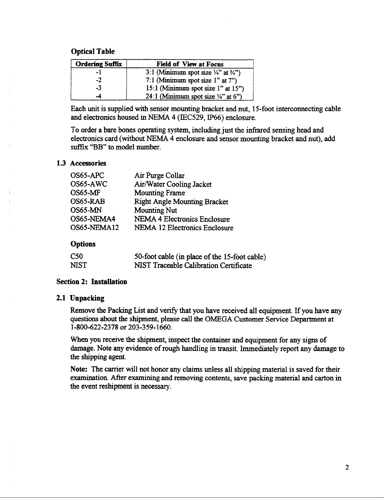
Optical Table
Each unit is supplied with sensor mounting bracket and
nut,
15-foot
interconnecting cable
and electronics housed in NEMA 4 (IEC529, IP66) enclosure.
To order a bare bones operating system, including just the
infrared
sensing head and
electronics card (without NEMA 4 enclosure and sensor mounting bracket and nut), add
suffix
“BB” to model number.
1.3 Accessories
OS65-APC
OS65-AWC
OS65-MF
OS65-RAB
OS65-MN
OS65-NEMA4
OS65-NEMA12
Air Purge
Air/water Cooling Jacket
Mounting Frame
Right Angle Mounting Bracket
Mounting Nut
NEMA 4 Electronics Enclosure
NEMA 12 Electronics Enclosure
Collar
Options
c50
NIST
50-foot
cable (in place of the
15-foot
NIST Traceable Calibration Certificate
cable)
Section 2: Installation
2.1
Unpacking
veri@
Remove the Packing List
and
that you have received all equipment. If you have any
questions about the shipment, please call the OMEGA Customer Service Department at
l-800-622-2378 or 203-359-1660.
When you receive the shipment, inspect the container and equipment for any
signs
of
damage. Note any evidence of rough handling in transit. Immediately report any damage to
the shipping agent.
Note:
examination. After examining and removing contents,
the event reshipment is necessary.
The carrier will not honor any claims unless all shipping material is saved for their
save
packing
material and carton in
Page 6
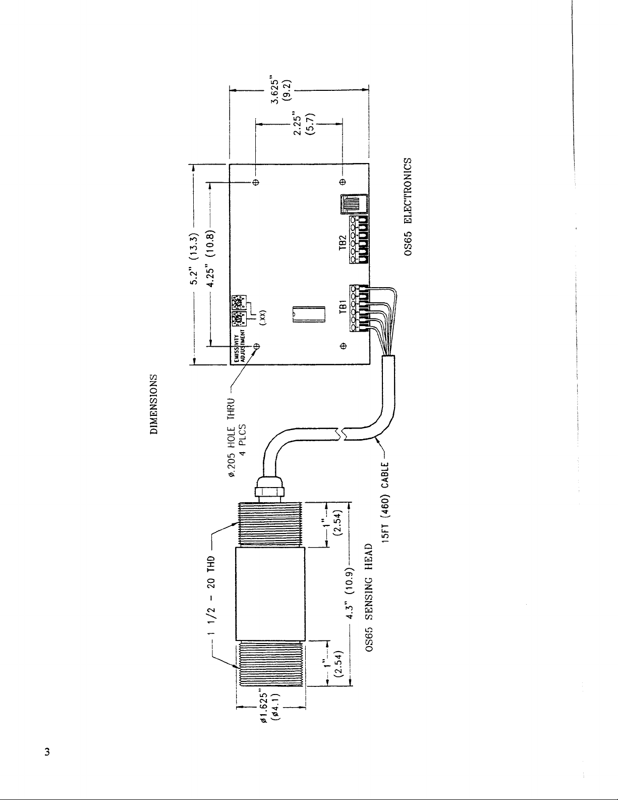
DlMENSIONS
t
@
1.625”
(164.1)
__-.--
J
.____._-
- -
f
--
1
l/2
-
20
THD
\
0.205 HOLE
THRU
It
-..-
(13.3)
5.2”
4.25” (10.8)
--
----.
II
4
(2:54)
.-._-_.__
L
OSB5
4.3 ”
SENSlNC
(1o.g)~--
HEAD
(2.54)
15FT (460)
CABLE
OS65 ELECTRONICS
_...__
..
__
..--
__-._.
.---
.--
Page 7
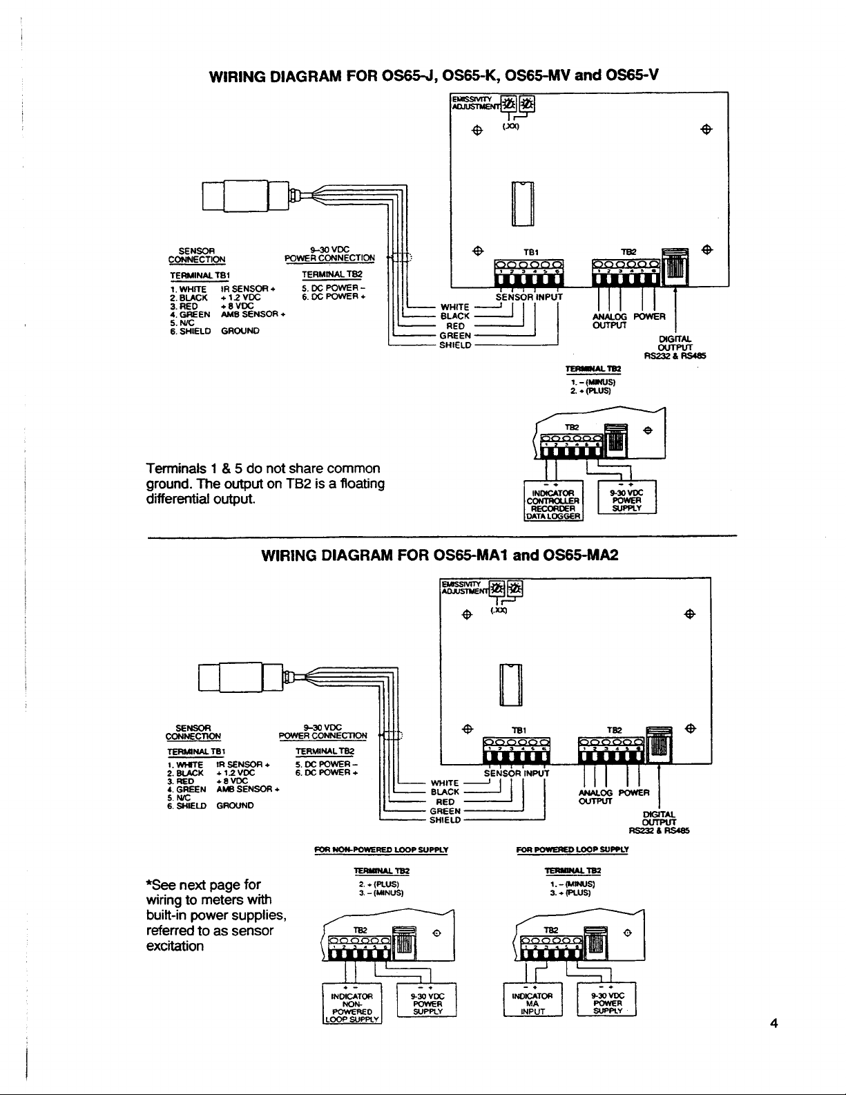
OS65J,OS6!bK,
OS6HAV
WIRING DIAGRAM FOR
and OS65V
TERMNALTBI
1. WHITE
I::kFK
4. GREEN
5. N/C
6. SHIELD GROUND
Terminals
TERMINAL
IR SENSOR
XF
AME SENSOR
&
5 do not share common
1
+
“6:~F%F
+
TB2
+
ground. The output on TB2 is a floating
differential output.
WIRING DIAGRAM FOR
+3
L
-- Bm -
WHITE
BLACK
OS65MAl
TBl
SENSOR INPUT
OS6!i-MA2
and
II
CZM%
TERMlNALTEll
l.Wl+TE
4. GREEN
5.
6. SHIELD GROUND
*See
wiring to meters with
built-in power supplies,
referred to as sensor
excitation
IR SENSOR
I;“,“”
EK $:
AMB
Nc
SENSOR
next page for
POWER
+
+
VDC
9-30
CONNECTlON
TERMINAL
%DCPOWER-
&DCPOWER+
ma
NouPowEl?Eo
TB2
091
SENSOR INPUT
PoaPowEREDwoPsuPPLY
)
Y6RuNuTBl
l.-wNlIs)
(PLUS)
*
3.
4
~DeJ iI
-
L
-
LOOPSUPPLY
lERulNuY62
FUJS)
2.
??
(MlNU6)
-
3.
GREEN
SHIELD
-
Page 8

Meter with internal power
supply for sensor excitation
SENSOR
CONNECTION POWER
TERMINALTBl
1. WHITE
;&A&K
4.
5.
SlilELD GROUN D
GFtEEh
N.c
!R SENSOR +
:2V& ‘C
AMBSENS~R
I
.-_.”
+
3
VDI
S-30
_I^..
CONNtr;
TERMINALTB2
%DCPOWER-
6. DC POWER +
POWER60 LOOP SUPPLY
FOR
11111.
WN
1
IIIII
IIL_
YERMNAL lB2
l.-fbmJUs)
-(PLUS)
3.
I
I
I
OS65MA2
T62
DIGJTAL
R&%X466
I
OS65MA1 and WIRING DIAGRAM FOR
I
I
-
-
-,,‘
with
TEb2
(Note
for
wiring terminals. 1 and 3 are not at common ground
must have a separate isolated power supply from the power supply on terminals 5 and
terminal 5, and
6.)
Page 9

Section
3.1
3:
Operation
Emissivity
A blackbody is defined as an object that emits the maximum theoretical amount of radiation
at a given temperature and has an emissivity at 1.0. The name blackbody is misleading
because it is not the color of the object, as much as the material and the surface finish of the
material that determines the emittance value.
The emittance of most organic substances (wood, cloth, plastic, and most paints) is
approximately 0.95. Metals with smooth, polished surfaces will have emittance values much
lower than 1.0.
3.2
Emissivity Adjustment
When
using an OS65 Series model to measure shiny, metallic
objects, the proper emissivity
adjustment must be made. This is easily accomplished by adjusting the emissivity pots on
the electronics board. One of the pots allows a coarse adjustment of the emissivity and has
from
range
0.10 to 0.90 in 0.10 steps. The second pot allows a fine adjustment of the
emissivity and has a range of 0.00 to 0.09 in 0.01 steps. To make the adjustment, use a small
screwdriver to turn the pots until the
arrows
are aligned with the proper setting. Determining
the proper setting can be done as follows.
1.
Heat a sample of the material to a known temperature as determined by a precise sensor.
Using the emissivity control of your OS65 Series instrument, adjust the indicated
temperature until it matches the temperature measured by the contact sensor. This value
of emissivity can now be used whenever the same material is measured.
a
2.
For relatively low temperatures (to approximately
500°F,
250°C),
a piece of masking
tape can be placed on the object and its temperature measured with the OS65 Series
instrument. Since the masking tape has an emissivity of approximately 1
measurement you obtain from it can be considered a “true”
temperature
.O,
the
and the object ’s
emissivity can be determined using the method described as above.
usiug
3.
For high temperatures, measure the object temperature
a thermocouple. Adjust the ’
emissivity control until the OS65 Series reading equals that of the thermocouple. For
exceedingly high temperatures, determine the emissivity using the emissivity value table
on page 7 of this manual.
4.
When a portion of the surface of the material can be coated, a dull black paint will have
emissivity of approximately 1 .O (other non-metallic coatings such as mold release may
be used also). Use this “true” temperature to determine the emissivity using the method
described in Example
1.
Standardized values of emissivity are available for most
materials.
A simplified table of emissivities is provided here. For a more detailed listing of
emissivities, refer
and D.P. Dewitt, published by
Publishing Company, 227 West
to
‘Thermal Radiative Properties ” (vol.
1FlKPlemu-n
17*
Data Corporation, subsidiary of Plenum
Street, New York, New York 10011.
7,8,
and 9) by Y.S. Touloukian
Page 10

Emissivity Tables
The following tables are provided as a guide for estimating the emissivity of various
that
materials. It is important to note
the actual emissivity, particularly for metals, can vary
greatly depending on surface finish oxidation, corrosion, or the presence of dirt, water, or
The best determination of emissivity can be made using the
oil.
techniques
described above.
Metals
Materials
Alumiuum
oxidized
uIloxidized
Polished
Brass
oxidized
Polished
Carbon
Graphite
chromium
Copper
oxidized
Polished
Gold
Polished
Iron
oxidize d
unoxidize d
Rusted
iron,
cast
oxidized
Unoxidized
Molten
Iron,
Wrought
Smooth
oxidized
Polished
Monel
Nickel
o?ddized
Unoxidized
PlatinIml
Polished
Black
silver
Steel
Cold-Rolled
(NiCu)
Emissivitv
0.20-0.55
0.09
0.05
0.50
0.03-0.05
0.40
0.10
0.40-0.80
0.03
0.02
0.50-0.90
0.15
0.50-0.70
0.60-0.95
0.20
0.20-0.30
0.70
0.30
0.40-0.60
0.05-0.10
0.10-0.40
0.20-0.50
0.10
0.30
0.09
0.03
0.70-0.90
Ground Sheet
Polished Sheet
oxidized
Stainless
zinc
o>ridized
Polished
Galvaoized
Non-Metals
Materials
Asbestos
Asphalt
Brick
Carbonmdum
GXi3LUiC
ClaY
Concrete
Cloth
Plate
Gravel
Grvp=
ICe
Limestone
Paint
Non-Metallic
Paper
Any
Color
Plastic
@asue
mils thickness)
Rubber
Sand
Snow
soil
Water
wood
Natural
(G=
20
0.40-0.60
0.20
0.70-0.90
0.20
0.10
0.03
0.20
Emissivity
0.95
0.95
0.95
0.90
0.95
0.95
0.95
0.95
0.85
0.95
0.80-0.95
0.98
0.95
0.90-0.95
0.95
0.90
0.95
0.90
0.90
0.90-0.98
0.93
0.90-0.95
7
Page 11

3.4
Comparison Measurements
When making comparison measurements on the same material, an approximation of the
emissivity will still give good results. Selecting a relatively low emissivity value will make
the difference in compared temperatures slightly larger than actual. When trying to locate a
slight temperature difference, setting the emissivity to 0.20 will provide the maximum
sensitivity, although the absolute temperature measurement will not normally be correct.
3.5 Maintenance
Due to its solid-state, sealed construction, the OS65 Series instruments require minimum
maintenance. The optics may require periodic inspection and cleaning if the sensor is in a
dirty environment. Use an optical cleaning solution (e.g. mild detergent) and a cotton swab.
Care
should be taken to prevent scratching the lens or its coating.
If
you are operating the
instrument in a dirty atmosphere, the optional lens air purge assembly is recommended.
Se&on
4:
Specifications
Accuracy:
Repeatability:
Spectral Response:
Emissivity
Response
Range:
Time:
Field of View
Power:
Environmental Ratings:
Ambient Operating
Sensing
EkCtl-OlliCS:
ComN!ction:
Max. Lead
(Ohms, Current Output Mode):
Load
@A,
Dimensions-
Sensing Head:
Electronics:
Weight-
Sensing Head:
Electronics
Electronics
Head:
Current-
Voltage Output Mode):
NEMA 4 enclosure):
NEMA 4 enclosure:
(FOV):
Wire
Resistance-
only (without
mounted
Range-
iu
(l°C),
+z?F
x&4
-
Hoc
185T)
7)/0.02
&O-50%
8-
0.10 to 0.99 digitally adjustable
300
3:1,minimumspotsize ’/4”at3/4”
7: 1, minimum spot size 1 ” at
15:1,
24: 1, minimum spot size
9-30
sensing
with either NEMA 4 electronics enclosure or
dust-tight
-180
32Oto
4.5 m
(Supply Voltage
1omAmaximum
10.9 cm x 4.1 cm (4.30 ” x 1.63”); l-112-20 thread
13.3 cm x 9.1 cm (5.25 ” x 3.62”)
0.3 kg (8 oz.)
0.1 kg (4 oz.)
1.2 kg (43.2 oz.)
of reading
14 microns
msec
(10 to 90%)
minimum spot size 1 ” at 15”
VDC,
40
head NEMA 4, dust-tight and water-tight
or drip-tight enclosure
85“C
to
(0 to
12OT
(15fi.
cable standard); Optional 15 m (50 ft. cable)
whichever is greater
+l% of reading or
T
s”
at 6”
NEh4A
12
8
Page 12

4.2
FIELD
OFVIEW DIAGRAMS
DISTANCE:
SENSOR
2
(II)
OWECT
TO
3
4
6
3:l
CLEAR
w
0
$
D
’
“,
6
83
?I?-
to
o-
a
(I)
DISTANCE: SENSOR TO OBJECT
DISTANCE: SENSOR TO
1’
4
2oan
toa
DISTANCE: SENSOR
DISTANCE:
E
,
DISTANCE: SENSOR TO
3om
SENSOR
TO
TO
OFklECT
06JEcT
OBJECT
6ocm 2ocm 4Ocm
(an)
lid
40fm
(CM
(in)
cfn
a.3
6Oa-n
(cm)OBJECT
4.1’
ld.5
15:l
z
iz-
‘og
a.
rn
CLEAR
APERTUR E
1’
ti
Z-
co
o -
%
MSTANCE:
12345678 9
U&
+
4
E
L
SENSOR TO OBJECT (in)
625
q
1.58Clll
5cm
10 cm
FOCUS
1/4’a:6’
15c m
OISTANCE: SENSOR TO
.w
4
1.7 cm
2Dcm
OBJECT (cm)
II I I ‘ I I r ,
24:l
Page 13

WATER
OS%-
COOL3NG
ACCESSORIES -
An%
JACKET
DIMENSIONS (INCHES)
MOUNTING FRAME
62.80
FOR 3
OS65-MF
l/8-27
BOLT CIRCLE
l/4”
OIA SCREWS
NPT
7
OS65MN
NOUNTING
!
3.50
Y -
2.k
j
I
I
NUT
c
E
-
2.00
01.52r
OS65-RAB
RIGHT ANGLE MOUNTING BRACKET
.25
HEX
OS65
APC
j---
I
COUAR
.2s
6.250
AIR PURGE
.125
R
4
b
I
7
/
i
3.00
--+.5
_!
10
Page 14

OS65”SV
1.5
2C
118
27
(3.81)
(C.32)
NP T
/
I - + -
1.15
(29.2)
WRENC H
FLAT S
iii
I
I
RIGdT
;o’;;i~;
THR U
ANGLE ADAPTOR
OS65-PA
(3.81)
1 .5
20
UN-2 B
THR U
_j
1.1 5
(29.2 )
i.5
N?T
(3.81)
ADA?TilR
PIPE
OS65-CA
(3.81)
l/2 1
112
NP T
UN-2929
11
CGNDiJ:T
SCALE.
A3APTC],?
i/2
Page 15

f-z- - \
/--
COVER
--- 6.75
I--
F
B
(171)
VIEW SHOWING CLAMP END (4 TOTAL)
USED ON NEMA-4,
N4-UX
---_-__
------_-_
--+--“.-_--_-_----_c__
I
--- _ -- __
------ -
=P
_._i
6.00
,-
(152)
SECTlON
L2.364
(60)
A- A
t;;
7.50 ---
(191)
N&MA
_
P
I
@ F -
-4
b-
75
19)
POL l CS lt R
&
NEMA 12 ENCLOSURE
1
PANELS
FTC FEET
INYOE
14
ANY 61
POwCR
ANO
CAUCE
12
GAUGE
CnAV
COA ll HC
UJ ,
sll.
7.50
-p-
-
(191)
-
4 . 00-- -
( 102 )
VIEW B-B
VIEW SHOWING HINGE END
USED ON NEMA-12,
Page 16

Sensor (Air/Water-Cooled Housing)
The
air/water-cooled housing (AWC) option allows the sensor to be used in ambient tempera-
tures up to 250°F
77°F
(25OC)
of 2 to 5
should be 3 to 5 cfm (1.4 to 2.4
PSID
liters) per minute; water temperature should be
Chilled water, below
(121°C)/3500F
(0.14 to 0.35
50°F
(
(175°C). It is supplied with two
liter&c)
Kg&
cm). Water flow should be approximately 0.5 gallons (2
50°
10°C),
is not recommended. To avoid condensation and lens dam-
with a pressure drop across the housing
to 80°F (10 ” to 27°C) for efficient cooling.
l/8”
NPT threads. Air flow
age, it is required to use the APC with the AWC.
PIACES
2
OS&j-AWC
WATER COOLING JACKET
Air Purge Collar (APC)
from
The APC accessory is used to keep dust, moisture, airborne particles and vapors away
the
lens. It may be installed before or after the bracket (see drawing) and screwed in fully. Air
flows into the
cfm
of 1 to 3
inants
(0.5 to 1.5
from
settling on the lens.
l/S”
NPT thread port and out the
I
&---
liter&z).
2.25
HEX
Clean or “instrument ” air is recommended to avoid contam-
1
!
--+
AlR
aperture.
front
.28
l/2-20-
OS65-APC
PURGE COLLAR
Air flow should be a maximum
l/8-27
NPT
-_Ikl.28
13
Page 17

DIGITAL OUTPUT WIRING (not field installable)
RS
232
TERMINAL TB3 TERMINAL TB3
2
TX0
2
RX0
3
5
CND BLACK
YELLOW
GREEN
TX/RX
3
TX/RX
ANALOG POWER
DIGITAL
OUTPUT
RS
48 5
YELLOW
GREEN
TOP VIEW
Protocol
9600
no
parity
8databits
1 start bit
1
stop bit
9600, N, 8,
FRONT VIEW
I
YELLOW
Interrogation
Format:
A one character command followed by a two character address and
possibly an additional two character address or a two character baud rate code.
Both
The address
required: i.e.,
I
commands: #AA
Baud Rate Code:
Reset:
is two characters between 00 and
FF hex.
OA rather than just A.
Unit at address AA responds with the IR temperature
@AABB
0/oAAo5
01
03
05
Turn
unit on with emissivity set at 00.
Unit at address AA gets new address BB
Unit at address
300 baud
1200 baud 04
4800 baud 06
AA is
02 600 baud
characters are
assigned
4800 baud
2400 baud
9600 baud
Default Conditions: Address:
Baud Rate:
A4
9600
14
Page 18
WIRIN G
DIAGRA M
SENSOR CONNECTION
TERMINAL
6
5
4
3
2
1
783
MilTi-
-
BLACK +
-
RED
GRiEN
-
-
N/ C
-
SHIELD GROUND
IR
SENSOR +
1.2
OS65-JX.
r \&&$j
VC C
TERMINAL TB4
16 + (PLUS)
17
Q-30 VDC
TERMINAL TB4
-
DC POWER
8
mV
and V
-
(MINUS)
TBt
11111
111
-
I
iI
SHIELD
OUTPU T
ST
TBl
d
‘INPISEI;SOR
WIRIN G
TERMINAL TB4
3 + TX/RX
1
COUPliTER
RS485
-
TX/R X
+-
HOST
TEA
II , I
GO’VDC
POWER
-
SUPPLY
- MA1 and MA2 with OS65
OS65
- CC4 Card Cage
FOR NON-POWERED LOOP SUPPLY FOR POWERED LOOP SUPPLY
TERMINAL TB4
(PLUS)
16 +
-
(MINUS)
13
TERMINAL TB4
-
(MINUS)
17
13 + (PLUS)
Page 19

WARRANTY/DISCLAIME R
OMEGA ENGINEERING, INC. warrants this unit to be free of defects in materials and workmanship for a
period
period to the normal
ensures that OMEGA ’s customers receive maximum coverage on each product.
If the unit should malfunction, it must be returned to the factory for evaluation. OMEGA ’s Customer
Service Department will issue an Authorized Return (AR) number immediately upon phone or written
request. Upon examination by OMEGA, if the unit is found to be defective it will be repaired or replaced at
no charge. OMEGA ’s WARRANTY does not apply to defects resulting from any.action of the purchaser,
including but not limited to mishandling, improper interfacing, operation outside of design limits,
improper repair, or unauthorized modification. This WARRANTY is VOID if the unit shows evidence of
having been tampered with or shows evidence of being damaged as a result of excessive corrosion; or
current, heat, moisture or vibration; improper specification; misapplication; misuse or other operating
conditions outside of OMEGA ’s control. Components which wear are not warranted, including but not
limited to contact points, fuses, and
OMEGA is pleased to offer suggestions on the use of its various products. However,
OMEGA neither assumes responsibility for any omissions or errors nor assumes liability for any
damages that result from the use of its products in accordance with information provided by
OMEGA, either verbal or written. OMEGA warrants only that the parts manufactured by it will be
as specified and free of defects. OMEGA MAKES NO OTHER WARRANTIES OR
REPRESENTATlONS
TITLE,
AND FITNESS FOR A PARTICULAR PURPOSE ARE HEREBY DISCLAIMED. LIMITATION OF
LIABILlTY
OMEGA with respect to this order, whether based on contract, warranty, negligence,
indemnification, strict liability or otherwise, shall not exceed the purchase price of the
component upon which liability is based. In no event shall OMEGA be liable for
consequential, incidental or special damages.
CONDITIONS: Equipment sold by OMEGA is not intended to be used, nor shall it be used: (1) as a “Basic
Component” under 10 CFR 21 (NRC), used in or with any nuclear installation or activity; or
applications or used on humans. Should any Product(s) be used in or with any nuclear installation or
activity, medical application, used on humans, or misused in any way, OMEGA assumes no responsibility
as set forth in our basic WARRANTY/DISCLAIMER language, and additionally, purchaser will indemnify
OMEGA and hold OMEGA harmless from any liability or damage whatsoever arising out of the use of the
Product(s) in such a manner.
of
13 months from date of purchase. OMEGA Warranty adds an additional one (1) month grace
one (1) year
OF ANY KIND WHATSOEVER, EXPRESSED OR IMPLIED, EXCEPT THAT OF
AND AU IMPLIED
The remedies of purchaser set forth herein are exclusive and the total liability of
WARRANTlES
product warranty to cover handling and shipping time. This
triacs.
INCLUDING ANY WARRANTY OF
MERCHANTABIUTY
(2)
in medical’
/
RETURN REQUESTS
Direct all warranty and repair requests/inquiries to the OMEGA Customer Service Department. BEFORE
RETURNING ANY PRODUCT(S) TO OMEGA, PURCHASER MUST OBTAIN AN AUTHORIZED RETURN
(AR) NUMBER FROM OMEGA ’S CUSTOMER SERVICE DEPARTMENT (IN ORDER TO AVOID
PROCESSING DELAYS). The assigned AR number should then be marked on the outside of the return
package and on any correspondence.
The purchaser is responsible for shipping charges, freight, insurance and proper packaging to prevent
breakage in transit.
FOR
WARRANTY
following information available BEFORE
contacting OMEGA:
1.
PO. number under which the product was
PURCHASED,
2. Model and serial number of the product under
warranty, and
3. Repair instructions and/or specific problems
relative to the product.
OMEGA’s policy is to make running changes, not model changes, whenever an improvement is possible. This affords
our customers the latest in technology and engineering.
OMEGA is a registered trademark of OMEGA ENGINEERING, INC.
0
Copyright 1996 OMEGA ENGINEERING, INC. All rights reserved. This document may not be copied, photocopied,
reproduced, translated, or reduced to any electronic medium or machine-readable form, in whole or in part, without prior
written consent of OMEGA ENGINEERING, INC.
RETURNS, please have the
FOR
for current repair charges. Have the following
information available BEFORE contacting OMEGA:
1. P.O. number to cover the COST
2. Model and serial number of product, and
3. Repair instructions and/or specific problems
INQUIRIES
NON-WARRANTY
of the repair,
relative to the product.
REPAIRS, consult OMEGA
Page 20

I
Were
Do I Find Everything
Need for
Process Measurement and Control?
OMEGA...Of Course!
TEMPERATURE
&
&
Thermistor Probes, Connectors, Panels
RTD
I_2
Thermocouple,
0 Wire: Thermocouple, RTD
0 Calibrators & Ice Point References
0 Recorders, Controllers
0 Infrared Pyrometers
&
Thermistor
&
Process Monitors
PRESSURE, STRAIN AND FORCE
&
G4’
Transducers
0 Load Cells
0 Displacement Transducers
0 Instrumentation
Strain Gauges
&
Pressure Gauges
&
Accessories
FLOW /LEVEL
&
b?
Rotameters, Gas Mass Flowmeters
0 Air Velocity Indicators
0 Turbine
0 Totalizers
/
Paddlewheel Systems
&
Batch Controllers
Flow Computers
Assemblies
pH/CONDUCTIVITY
&
pH
Electrodes, Testers
0’
0
Benchtop
0
Controllers, Calibrators, Simulators
0
Industrial
/
Laboratory Meters
&
Conductivity Equipment
pH
Accessories
&
Pumps
DATA ACQUISITION
&
@’
Data Acquisition
0
Communications-Based Acquisition Systems
0
Plug-in Cards for Apple, IBM
0
Datalogging Systems
0
Recorders, Printers
Engineering Software
&
Compatibles
&
Plotters
HEATERS
0
Heating
0
Cartridge
0
Immersion
0 Flexible Heaters
0
Laboratory Heaters
Cable
&
Strip Heaters
&
Band Heaters
ENVIRONMENTAL
MON ITORING AND CONTROL
&
Metering
Refractometers
Pumps
Air, Soil
Industrial Water
pH,
Conductivity
Control Instrumentation
&
Tubing
&
Water Monitors
&
Wastewater Treatment
&
Dissolved Oxygen Instruments
Ml770 0299
 Loading...