

Page 1
http://www.omega.com
e-mail: info@omega.com
OS6000
OS6000
OS6000 OS6000
Fiber optic system
OS8000
Sight optic system
Page 2

OMEGAnetSM On-Line Service
Internet e-mail
http://www.omega.com
USA:
ISO 9001 Certified
Canada:
USA and Canada:
Mexico and
Latin America:
Servicing North America:
One Omega Drive, Box 4047
Stamford, CT 06907-0047
Tel: (203) 359-1660
e-mail: info@omega.com
976 Bergar
Laval (Quebec) H7L 5A1
Tel: (514) 856-6928
e-mail: info@omega.ca
For immediate tech nic al or ap p l ic ati on as s is ta nce :
Sales Service: 1-800-826-6342 / 1-800-TC-OMEGA
Customer Service: 1-800-622-2378 / 1-800-622-BEST
Engineering Service: 1-800-872-9436 / 1-800-USA-WHEN
TELEX: 996404 EASYLINK: 62968934 CABLE: OMEGA
Tel: (95) 800-826-6342
En Español: (95) 203-359-7803
e-mail: espanol@omega.com
SM
SM
SM
Servicing Europe:
info@omega.com
FAX: (203) 359-7700
FAX: (514) 856-6886
FAX: (95) 203-359-7807
Benelux:
Czech Repu blic:
France:
Germany/Austria:
United Kingdom:
ISO 9002 Certified
It is the policy of OMEGA to comply with all worldwide safety and EMC/EMI regulations that apply. OMEGA is constantly
pursuing certification of its products to the European New Approach Directives. OMEGA will add the CE mark to every
appropriate device upon certification.
The information contained in this document is believed to be corrected but OMEGA Engineering Inc. accepts no liability for any errors it
WARNING: These products are not designed for use in, and should not be used for, patient connected applications.
Postbus 8034, 1180 LA Amstelveen, The Netherlands
Tel: (31) 20 6418405
Toll Free in Benelux: 0800 0993344
e-mail: nl@omega.com
ul. Rude armady 1868, 733 01 Karvina-Hranice, Czech Republic
Tel: 420 (69) 6311899
Toll free: 0800-1-66342
e-mail: czech@omega.com
9, rue Denis Papin, 78190 Trappes
Tel: (33) 130-621-400
Toll Free in France: 0800-4-06342
e-mail: france@omega.com
Daimlerstrasse 26, D-75392 Deckenpfronn, Germany
Tel: 49 (07056) 3017
Toll Free in Germany: 0130 11 21 66
e-mail: info@omega.de
One Omega Drive , River Bend Technology Centre
Northbank, Irlam, Manchester
M44 5EX, Engl and
Tel: 44 (161) 777-6611
Toll Free in United Kingdom: 0800-488-488
e-mail: info@omega.co.uk
contains, and reserves the right to alter specifications without notice.
FAX: (31) 20 6434643
FAX: 420 (69) 6311114
FAX: (33) 130-699-120
FAX: 49 (07056) 8540
FAX: 44 (161) 777-6622
2
Page 3

INTRODUCTORY NOTE
A
TTENTION
: T
HIS MANUAL IS VALID FOR
8454
THAN
OS8000
WITH SERIAL NUMBER HIGHER THAN
9233, OS6000
WITH SERIAL NUMBER HIGHER
This publication contains operating instructions, as well as a description of the principles of operation, of
OS6000 & OS8000 Series IR thermometers.
This information covers all models of the instrument, including the basic equipment and its options and
accessories. This m anual is a complete “USER GU IDE”, providing step-by-s tep instructions to operate the
instrument in each of its designed functions.
OMEGA has used the best care and efforts in preparing this book and believes the information in this
publication are ac c ur ate. Th e OMEGA products are subjec ted t o c ont in uous improvement, in order to pursue
the technological leadership; these improvements could require changes to the information of this book.
OMEGA reserves the right to change such information without notice.
No part of this document may be stored in a retrieval system, or transmitted in any form, electronic or
mechanical, without prior written permission of OMEGA Engeneering.
OS IR thermomet ers uses s ophisticat ed analogic an d digital tec hnologies. Any main tenance operation must
be carried out by qualified personnel
. We recommend to contact our technicians for any support
ONLY
requirements.
OS is fully tested in conformity with the directive n°89/336/CEE Electromagnetic Compatibility. OMEGA
shall not be liable in any event, technical and publishing error or omissions, for any incidental and
consequential damages, in connection with, or arising out of the use of this book.
3
Page 4

TABLE OF CONTENTS
1 GENERAL DESCRIPTION...................................................................................................................5
1.1 OS8000 specifications......................................................................................................................................6
1.2 OS6000 specifications......................................................................................................................................7
1.3 OS8000 ordering table .....................................................................................................................................8
1.4 OS6000 ordering table .....................................................................................................................................9
2 PHYSICAL DESCRIPTION ................................................................................................................ 10
3 PRINCIPLE OF OPERATION ............................................................................................................ 11
3.1 Emissivity adjustment.....................................................................................................................................11
3.2 Response time adjustment.............................................................................................................................11
3.3 OS8000 principle............................................................................................................................................11
3.3.1 Electronic module ......................................................................................................................................11
3.4 OS6000 principle............................................................................................................................................11
3.4.1 Electronic module ......................................................................................................................................12
4 UNPACKING ......................................................................................................................................13
4.1 Pre-operational check.....................................................................................................................................13
5 START-UP..........................................................................................................................................14
5.1 OS8000 operations.........................................................................................................................................14
5.1.1 Positioning .................................................................................................................................................14
5.1.2 Mounting and Alignment ............................................................................................................................14
5.1.3 Electrical connection..................................................................................................................................14
5.1.4 Pointing systems........................................................................................................................................15
5.1.5 Air supply ...................................................................................................................................................15
5.1.6 Water Supply .............................................................................................................................................16
5.2 OS6000 operations.........................................................................................................................................16
5.2.1 Optical Head Positioning ...........................................................................................................................16
5.2.2 Optic Head Mounting and Alignment .........................................................................................................16
5.2.3 Air Supply ..................................................................................................................................................16
5.2.4 Optic Fiber Connection ..............................................................................................................................17
5.2.5 Electronic module mounting ......................................................................................................................17
5.2.6 Head mounting bracket..............................................................................................................................17
5.2.7 Electrical connection..................................................................................................................................17
6 MAINTENANCE..................................................................................................................................19
6.1 Purge Air Supply.............................................................................................................................................19
6.2 Water Supply..................................................................................................................................................19
6.3 Optic cleaning.................................................................................................................................................19
6.4 Protection and Support Device.......................................................................................................................19
6.5 Mounting Device.............................................................................................................................................19
6.6 Electrical connection cable .............................................................................................................................20
6.7 Storage...........................................................................................................................................................20
7 SUPPORT AND ACCESSORIES....................................................................................................... 21
7.1 Air Purge ........................................................................................................................................................21
7.1.1 OS8000 air purge and water cooling devices ............................................................................................21
7.1.2 OS6000 Purge Air Device..........................................................................................................................21
7.2 Pointing Tubes................................................................................................................................................22
APPENDIX.......................................................................................................................................................24
A1 How to determine an object emissivity ...........................................................................................................25
A1.1 Typical Emissivity Values ..........................................................................................................................25
A1.2 Metals - Typical Emissivity Values.............................................................................................................26
A1.3 Non-Metals - Typical Emissivity Values ....................................................................................................27
4
Page 5

1 GENERAL DESCRIPTION
The temperature measurement of a liquid or gaseous compound has been successfully made with thermoelectric or
expansion thermometers thanks to the good thermal exchange between the fluid and the sensor.
With solid bodies a good thermal exchange is difficult to be obtained and an additional measuring error should be
considered.
Direct contact measurement is impractical when the object being measured is moving, or electrically hazardous, or for
any other reasons cannot be touched with a thermocouple. A non-contact IR temperature measurement is a solution to
the above problems. Other applications benefit because non-contact thermometers do not add or remove heat or disturb
the process in any way.
There are two different series of
OS8000
OMEGA
Every
4/20 mA linear output version has the emissivity and response time adjustments accessible.
For accurate positioning of
as accessories.
OS6000
The fiber optic head is the ideal solution for: temperature measurements of surface that afford no direct straight-sight
view, installing the fiber optic head in remote locations with environments at extreme temperatures, avoiding the
requirement of water cooling systems.
OMEGA
Every
! Optic head
! Fiber optic
! Electronic module able to contain the IR sensor and all electronic circuits. The 4/20 mA linear output version
The infrared spectral band energy emitted by the measured objects is focused by the "optic head - optic fiber" system
installed on the sensor and converted in to an electric signal. The thermometer output signal resulting after its
amplification has a 4/20 mA value based upon the object temperature.
Common Features
2-Wire 4-20 mA Linear output
Repeatability ±0.25% rdg
Fast response 50/100 msec
OS6000 Additional features
Wide temperature range: 300 to 1600°C (592 to 2912°F)
.8 and 1.6µm Spectral response
Fiber optic cable lengths 12 to 26’ (3.5 to 8 meters)
Five target size vs. distance from .08” (2mm) size @ 3” (75mm) distance to 4.7” (12mm) size @ 35” (900mm) distance
Compressed air conditioning option
thermometer consists of a cylindrical chassis with a: lens, filter, IR sensor, and electronic circuits. The
thermometer consists of:
has the emissivity and response time adjustments accessible.
OMEGA
OS8000
thermometers available:
thermometer, a telescope and a laser pinpointing removable systems are available
OS8000 Additional features
Wide temperature range: -40 to 1700°C (-40 to 3092°F)
Seven Spectral response ranges
Line of sight viewing with lens system
Optional laser pointer & Sighting telescopes
Compressed air and water conditioning option
5
Page 6
1.1 OS8000 specifications
Measuring ranges:
•
see ordering table
Spectral band:
•
see ordering table
Limit of error:
•
OS8003/04/05/12/13/14
Other models
Repeatability:
•
OS8003/04/05/12/13/14
Other models
Temperature stability:
•
<0.02% / °C for the band exceeding +15 to +35°C
Response time:
•
OS8003/04/05/12/13/14
Other models
Ambient temperature:
•
from 0 to +60 °C (without cooling)
Storage temperature:
•
from -30 to +60 °C
Output signal:
•
4/20 mA 2 wire current loop
Protection:
•
IP65
Loop power supply:
•
from 18 to 32 Vdc
Dimension / Weight:
•
OS8003/04/05/12/13/14:
Other models:
with ambient temp. from +15 to +35 °C
± (0.5% of rdg. + 1 °C)
± (1% of rdg. + 1 °C)
± 0.25% of the reading
± 0.5% of the reading
from 50 ms to 10 s adjustable
from 100 ms to 10 s adjustable
2.24D x 8.35”L – 1.76 lb (57D x 212mm L - 0.8 Kg)
2.24D x 7.48”L – 1.76 lb (57D x 190mm L - 0.8 Kg)
6
Page 7
1.2 OS6000 specifications
Measuring ranges:
•
see ordering Table
Limit of error:
•
±(0.5% of rdg + 1 °C) with ambient temp. from +15 to +35 °C
Repeatability:
•
±0.25% of the reading
Temperature stability
•
< 0.02% of rdg / °C for the band exceeding +15 to +35°C
Response time
•
from 50 ms to 10 s adjustable
Spectral band
•
0.8 to 1.6 µm
Fiber to optic connection:
•
fast lock coupling
Operating temperature
•
optical adapter: 200 °C max
fiber optic: 200 °C max
electronic module: from 0 to +60 °C
Storage temperature
•
from -30 to +60 °C
Output signal
•
4/20 mA 2 wire 24 Vdc - Load 0 ÷ 300 Ω
Protection:
•
IP65
Loop power supply
•
from 18 to 32 Vdc
Dimension / Weight
•
electronic module: 2.24D x 4.67”L – 1.1 lb (57D x 121mm L - 0.5Kg)
fiber optic: 0.31” (8mm) D
optic head: code 1,2 & 3 0.63 D x 2.05” L (16 x 52 mm)
optic head: code 4 & 5 1.18 D x 3.78” L (30 x 94 mm)
:
:
:
:
:
:
:
:
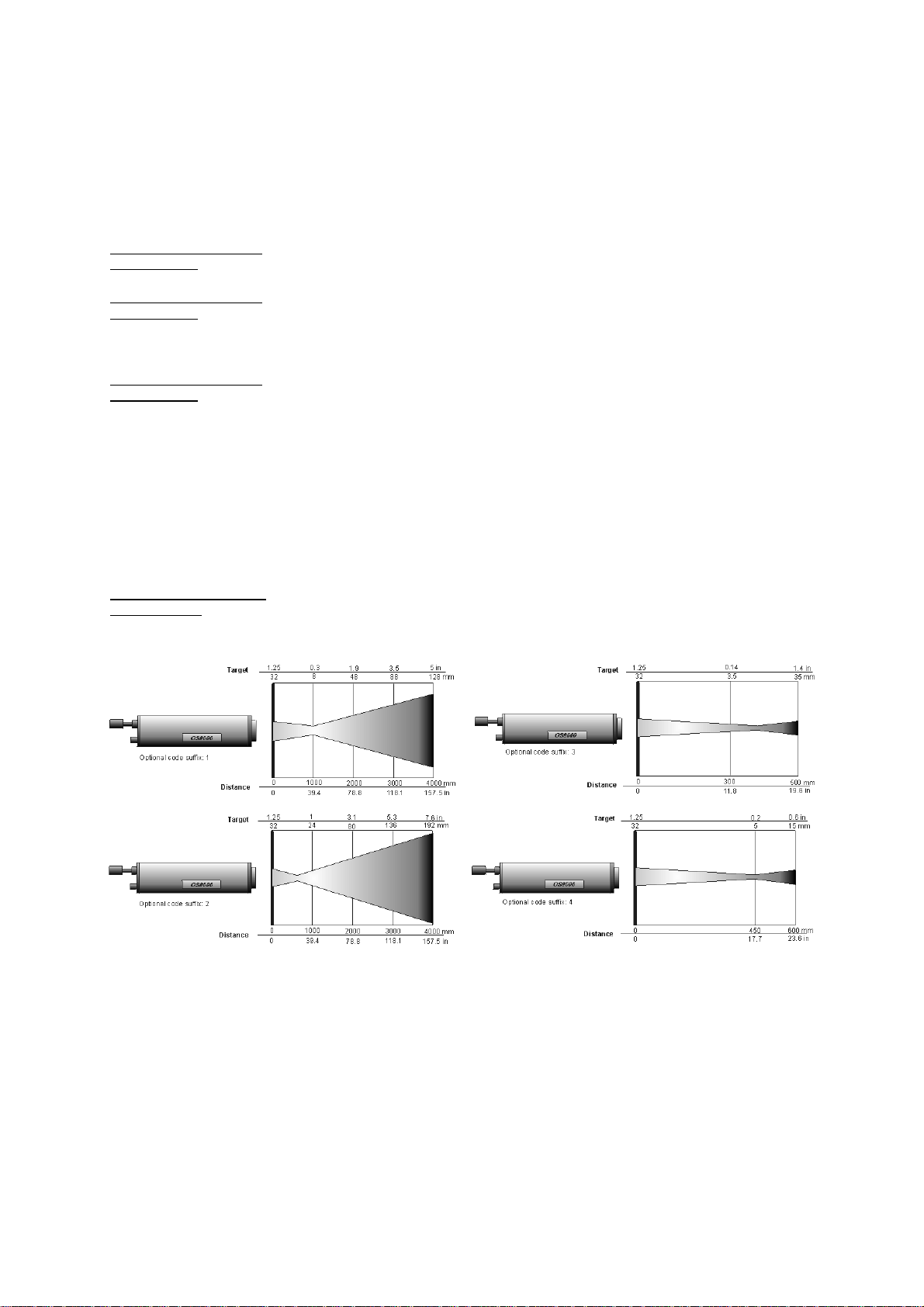
Distance [in] 0
Target [i n] 0.3
Optional code
suffix: D1
Distance [mm] 0
Target [mm] 7
Distance [in] 0
Target [in] 0.3
Optional code
suffix: D2
Distance [mm] 0
Target [mm] 7
Distance [in] 0
Target [in] 0.9
Optional code
suffix: D5
Distance [mm] 0
Target [mm] 20
3
0.08
75
2
5.9
0.4
150
11
5.9
0.15
150
4
11.8
1.1
30029400
11.8
0.6
300
15
15.7
1.6
41
15.7
0.9
400
22
35
0.47400.79
900
12
20
2
500
53
20
1.2
500
30
1000
20
Distance [in] 0
Target [in] 0.3
Optional code
suffix: D3
Distance [mm] 0
Target [mm] 7
Distance [in] 0
Target [in] 0.9
Optional code
suffix: D4
Distance [in] 0
Target [in] 20
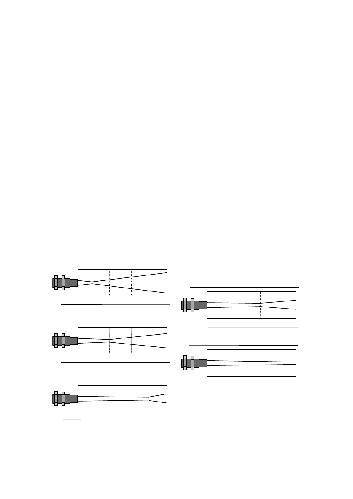
OS6000 Target Size vs. Distance
11.8
0.31
300
8
15.7
0.5
400
13
20
0.7
500
18
20
0.2
500
5
7
Page 8

1.3 OS8000 ordering table
To Order
(specify model number)
Spectral
Model No.
response CWL Temperature range Typical application
OS8001-2
OS8002-2
8-14µ
OS8003(*)
OS8004(*)
1µ
OS8005(*)
OS8006-2
OS8007-2
OS8008-2
3.43µ
5.10µ
OS8009-2
OS8010-2
OS8011-2
7.90µ
3.86µ
OS8012(*)
OS8013(*)
1.6µ
OS8014(*)
* Add optics code
Optics code
Suffix Target/Distance ratio
-1
.03 @ 39.4” (8mm OD at 1000mm)
only with OS8003/04/05/12/13/14
-2
1 @ 39.4” (24mm OD at 1000mm)
only with OS8001/02/06-11
-3
.14 @ 11.8” (3.5mm OD at 300mm)
only with OS8012/13/14
-4
.2 @ 17.2” (5mm OD at 450mm)
only with OS8012/13/14
-40 to 200°C (-40 to 392°F)
0 to 500°C (-32 to 932°F)
600 to 1100°C (1112 to 2012°F)
700 to 1300°C (1292 to 2372°F)
900 to 1600°C (1652 to 2912°F)
50 to 200°C (122 to 392°F)
100 to 400°C (212 to 752°F)
100 to 1000°C (212 to 1832°F)
300 to 1600°C (572 to 2912°F)
0 to 600°C
(-32 to 1112°F)
600 to 1700°C
(1112 to 3092°F)
300 to 900°C (572 to 1652°F)
300 to 1300°C (572 to 2372°F)
400 to 1350°C (752 to 2462°F)
General low temperature applications such as textile,
printing, paper, food, rubber, Thick plastic, paint.
High temperature applications such as metal treating,
foundries, forging, glass gob, iron and steel.
Thin film plastic (CH composition) such as:
polyethylene, polypropylene, polystyrene, vinyl and
nylon.
Glass under-skin such as bending, forming,
tempering, laminating and anealing.
Thin film plastic polyester, fluorocarbon and very thin
glass
Objects through clean flames such as reformer tubes,
chemical reactor, klins.
Applications which require high accuracy in low
emissivity values
Accessories
Suffix Description
OS8000-0
OS8000-11
Sighting telescope
Economy support with air water cooling and air
purge
OS8000-13
OS8000-14
Removable laser pointer
Alignment support
Unit comes with: optics, sensor, 4 to 20 mA linear output, calibration report and instruction manual.
8
Page 9

1.4 OS6000 ordering table
To Order
(specify model number)
Spectral
Model No.
response
CWL
OS6001(*) †
OS6002(*) †
1µ
OS6003(*) †
OS6004(*)-C2
OS6005(*)-C2
1.6µ
OS6006(*)-C2
* Add optics code
† Add fiber optic length
Optics code
Suffix Target/Distance ratio
-D1
-D2
-D3
-D4
-D5
.08 @ 3” (2mm OD at 75mm)
.15 @ 5.9” (4mm OD at 150mm)
.31 @ 11.8” (8mm OD at 300mm)
.2 @ 20” (5mm OD at 500mm)
.47 @ 35” (12mm OD at 900mm)
Fiber optic lenght
Suffix Description
-C2
-C3
-C4
12’ (3.5m)
20’ (6m)
26’ (8m)
Temperature range Typical application
600 to 1100°C (1112 to 2012°F)
700 to 1300°C (1292 to 2372°F)
900 to 1600°C (1652 to 2912°F)
300 to 900°C (572 to 1652°F)
300 to 1300°C (572 to 2372°F)
400 to 1350°C (752 to 2462°F)
High temperature applications such as metal treating,
foundries, forging, glass gob, iron and steel.
Applications which require high accuracy in low
emissivity values
Accessories
Suffix Description
OS6000-11
OS6000-16
OS6000-18
Air purge collar
Electronics support
Air purge system
Unit comes with: head, fiber optic, electronic module with 4 to 20mA linear output, calibration report and instruction
manual.
9
Page 10

2 PHYSICAL DESCRIPTION
OMEGA OS8000
OS8000
internal body blocking system.
The internal body is aluminum made with anti-reflection treatment. It provides the room for the optic system, the pointing
system, the optic filter, the sensor and the electronics for signal conditioning.
An optional Pt100 sensor allows to detect the internal temperature, with the possibility to supply a control signal when the
environment is critical.
OS8003/04/05/12/13/14 models
OS8001/02/06/07/08/09/10/11 models
OMEGA OS6000
The
- optic head
- optic fiber
- electronic module
radiation thermometers are protected by an extruded aluminum that provides the positioning guidelines and the
57
190
230
57
150
190
OS6000
is composed of:
The infrared radiation emitted by the target is focused by a lens placed on the optic head, and transmitted, by the fiber
optic, to the sensor installed on the electronic module, that provides the treatment of the thermoelectric signal, generating
a 4/20 mA signal.
optical head
The
is a metallic cylinder with a length of 52 mm and a diameter of 16 mm (or with length of 94mm and
diameter of 30mm).
It has 2 hexagonal fixing washers to ease the installation. A 13 mm lens, a filter and a field stop that defines, with very
high precision, the result cones of the optic system are placed into the cylinder.
The flexible
fiber optic
has an 8 mm diameter with different lengths.
It is protected by a spiraled metallic sheath covered with silicon rubber, and it's suitable to be used for ambient
temperatures higher than 200 °C.
Its function is to interconnect the optical head with the electronic module where the sensor is inserted.
electronic module
The
57 mm - length 130 mm), with an IP65 protection.
φ
(
which connects and treats the signal is placed in an anodized aluminum cylinder
Its function is to generate an electric signal (4/20 mA) proportional to the measured temperature.
Code 1, 2 & 3
16
52
94
30
57
OS6000
130
Code 4& 5
10
Page 11

3 PRINCIPLE OF OPERATION
3.1 Emissivity adjustment
The IR thermometers incorporate, on the electronic module, a potentiometer to adjust the thermometer to the target
emissivity value.
3.2 Response time adjustment
The IR thermometers incorporate, on the electronic module, a potentiometer to adjust their response time (from
50/100ms to 10s). This is a feature able to permit the measurement also in unstable measuring condition (e.g. flames,
moving target, etc.)
3.3 OS8000 principle
The optical system of
filter and a field stop that defines the visual cone and therefore the dimensions of the target.
A filter is placed between the optic system and the infrared radiation sensor, to determine the working spectral band and
to eliminate any radiation effect in the visible band.
In order to obtain a correct alignment of the thermometer, sighting devices or laser pointers are available. When the
alignment is achieved the sighting telescope or laser pointer can be removed.
The infrared radiation is converted, by the sensor, into an electric signal with a non-linear dependence on the target
temperature. The electrical signal is linearized and amplified by the internal circuitry that makes available a 4/20 mA
linear output.
OS8000
transmitters collects the infrared energy into the infrared detector through a single lens, a
3.3.1 Electronic module
The components used in the electronic circuits allow to use the optic head in environments with an ambient temperature
up to +60 °C.
The 4/20 mA linear with temperature circuit incorporates the emissivity and response time adjustment. It requires a
24Vdc power supply and can be used together with the any other measurement/regulation system.
Fig. 3.3.1: Connectors and controls of OS8000
3.4 OS6000 principle
The infrared radiation emitted by the target is focused by the optic system, with a collector that has a sensitivity covering
the spectral band required.
The optic system geometry, combined with a field stop, determines with accuracy the dimension of the target and the
distance between the thermometer and the target.
A filter is placed, between the optic system and the infrared radiation sensor, to determine the working spectral band and
to eliminate any radiation effect from the visible band.
The infrared radiation is converted into an electric signal proportional to the target temperature in a non-linear mode.
The electric signal is treated by the internal circuitry that makes an output from 4 to 20 mA signal available.
11
Page 12

3.4.1 Electronic module
The components used in the electronic circuits allow to use the optic head in environment with an ambient temperature
up to +60 °C.
The 4/20 mA linear with temperature circuit incorporates the emissivity and response time adjustment. It requires a
24Vdc power supply and can be used together with the any other measurement/regulation system.
Fig. 3.4.1: connectors and controls of OS6000
12
Page 13

4 UNPACKING
Remove the instrument from its packing case and remove any shipping ties, clamps or packing materials.
Carefully follow any instruction given by any attached tags.
Inspect the instrument from scratches, dents, damages to case corners etc. which may have occurred during shipment.
If any mechanical damage is noted, report the damage to the shipping carrier and then notify
directly, and save the damaged packaging for inspection.
A label, on the back panel, indicates the serial number of the instrument. Refer to this number for any inquiry for service,
spare parts supply or application and technical support requirements.
every information regarding your instrument.
OMEGA Engineering
4.1 Pre-operational check
Store the instrument in the original package, at a temperature from –30 °C to +60°C, with R.H. less than 90%.
WARNING
OMEGA Engineering
keeps a data base with
T
HE FIBRE OPTIC IS A CRITICAL COMPONENT IN THE SYSTEM
T
O BEND, TO TWIST, OR TO PULL THE FIBRE OR THE CONNECTORS CAN DAMAGE THE SAME FIBRE MODIFYING THE OPTICAL
TRANSMISSION OF THE COMPONENT AND COMPROMISING THE CORRECT OPERATION OF THE MEASURE SYSTEM
.
.
13
Page 14

5START-UP
5.1 OS8000 operations
! Connect the air or the water tubes, making sure to have the possibility to align and point the thermometer.
! Verify the support to be clean and free.
! Insert the connector.
WARNING
D
O NOT LEAVE THE THERMOMETER IN A HOT AREA WITHOUT HAVING CONNECTED THE COOLING SYSTEM
After the connection to a controller or monitor, the thermometer is ready to operate (see the relevant manual for the
controller or monitor).
.
5.1.1 Positioning
The optic head has to be installed in an accessible place for any further maintenance operation, and it hasn't to be
exposed to excessive heat, smoke and water vapors.
The optical path between the lens and the target, should be as much free as possible from smoke and steam.
The pointing axis should be placed with a 90° angle against the target surface.
N
OTE: A LARGE NUMBER OF MATERIALS HAVE THE EMISSIVITY COEFFICIENT DEPENDENT ON THE VIEWING ANGLE
(
MORE THAN
Before the installation, it's useful to look at the tables supplied together with the instrument, in order to determine the
correct distance and visual field.
45°)
CAN INDUCE A LARGE ERROR IN MEASUREMENT
.
. L
ARGE AN GLES
5.1.2 Mounting and Alignment
Install the mounting plate in a suitable place in the most favorable position from a thermal, and mechanical point of view.
Mount on the plate, if it is necessary, the protection device and the purge air ejector.
If a cooling jacket has to be used, use the water outlet on the upper part of the support in order not to create air bubbles
in the jacket.
WARNING
IT ADVISABLE TO USE A PROTECTIVE SCREEN DURING THE THERMOMETER ALIGNMENT OPERATIONS IF THE TARGET HAS A STRONG
RADIATION
In order to align the support with the target, look through the support hole (without the thermometer) and find the best
position. It's important for the optic path to be free from any obstacle. In particular, when the surface is targeted through a
hole, the hole diameter has to be big enough according to the distance from the instrument.
.
5.1.3 Electrical connection
The temperature signal is converted, amplified and linearized by the internal electronics that makes available a 4/20 mA
linear output. OMEGA supply a connector for 4/20 mA active current loop connection.
14
Page 15

A
B
D
Fig. 5.1.3a: OS8000 connector (soldering side)
To connect OS8000 to a measurement or control system, follow the table below:
Pin A (+)
o (+)
24 Vdc power supply
OS8000
Connector
Pin B (-)
Pin D (GND)
o (-)
[
[
o (-)
INDICATOR INPUT 4 ÷ 20 mA
o (+)
Fig. 5.1.3b: Power supply for OS8000 using external current loop
5.1.4 Pointing systems
A removable telescope is optionally available for an accurate alignment of the thermometer. It is particularly useful when
little objects are to be targeted.
The telescope has to be inserted in the thermometer, and removed when the alignment has been done.
In order to insert the telescope, the protection cap must be removed.
The focusing of the target must be carried-out varying the telescope introduction inside the thermometer body. This
operation can be also carried-out by using the laser pointing system.
5.1.5 Air supply
According to the application, it could be necessary to cool the thermometer using an air flow. The maximum pressure for
an air purge system is 0.7 bar. Just for a normal air purge, only the tenth part of this flow is required.
Remember that the air tube must have a diameter bigger enough not to have flow losses.
W
HEN A PURGE AIR IS USED, IT MUST BE CLEAN AND DRY
I
F THE AIR ISN'T PERFECTLY CLEAN, TRACKS OF OIL AND DIRT MAY DEPOSIT ON THE LENS
I
MPORTANT NOTE
. T
HE DIFFUSOR PRODUCES A LAMINAR FLOW THAT KEEPS THE LENS CLEAN
:
.
.
15
Page 16

I
MPORTANT NOTE
:
W
HEN MEASURING TEMPERATURES INSIDE OVENS, DO NOT USE ANY AIR COMING FROM THE FAN OF THE OVEN
OVEN, IN FACT, MAY VARY, AND THE PRESSURE ON THE THERMOMETER MAY BE NOT SUFFICIENT TO GRANT ITS CLEANING AND
COOLING
.
. T
HE AIR FROM THE
5.1.6 Water Supply
When the thermometer is installed in a very hot environment it is useful to cool it with water. The water must be clean in
order not to create any obstruction and cold enough to ease the thermometer cooling.
I
MPORTANT NOTE
D
O NOT USE TOO COOL WATER AS IT COULD CREATE CONDENSE ON THE SUPPORT OR ON THE LENS
I
T IS ADVISABLE TO HAVE A LOW WATER FLOW TO KEEP THE TEMPERATURE OF THE SUPPORT HIGHER THAN THE DEW-POINT OF A HOT
AND HUMID DAY
T
HE FLOW SHOULDN'T BE HIGHER THAN
0.7
BAR AND THE AMBIENT TEMPERATURE SHOULD BE LOWER THAN
:
.
.
200°C.
The cooling water line has to be made using the following precautions:
! The outlet of the cooling jacket must be kept free in order to control the flow and water temperature;
! It's useful to use a thermometer to control the water temperature.
: I
N
OTE
N CLOSE CIRCUIT SYSTEMS, ALWAYS USE A FLOW WATER WITH A LOW LEVEL ALARM
5.2 OS6000 operations
5.2.1 Optical Head Positioning
The optic head has to be installed in an accessible place for any further maintenance operation, and it hasn't to be
exposed to excessive heat, smoke and water vapors.
The optical path between the lens and the target, should be as much free as possible from smoke and steam.
The pointing axis should be placed with a 90° angle against the target surface.
N
OTE: A LARGE NUMBER OF MATERIALS HAVE THE EMISSIVITY COEFFICIENT DEPENDENT ON THE VIEWING ANGLE
(
MORE THAN
45°)
CAN INDUCE A LARGE ERROR IN MEASUREMENT
.
. L
ARGE AN GLES
Before the installation, it' s useful to look at the tables supplied together with the instrument, in order to determine the
correct distance and visual field.
5.2.2 Optic Head Mounting and Alignment
Fix the optic head on the suitable support using the supplied hexagonal washers. Place the support in the best possible
position from a thermal point of view (the maximum ambient temperature is 200 °C), from a mechanical point of view
(minimum to no vibration) and environmental one (dust, smoke, vapors, and so on).
Align the support with the surface to be measured, center the target by looking through the optic head after the optic fiber
has been removed. In order to make the pointing operations easier, it's possible to have a pointing device that aligns the
head using a luminous track. It's important for the optic path to be free from any obstacle. In particular, when the surface
is targeted through a hole, the hole diameter has to be big enough according to the distance from the instrument.
5.2.3 Air Supply
In the applications where a purge air is needed to clean the optic system, adjust the flow at 0.5 bar. If a cooling effect is
required, embance the flow up to 10 bar. The supply tubing system has to be designed with a correct diameter in the
thermometer proximity, in order not to have charge losses.
I
MPORTANT NOTE
T
HE PURGE AIR MUST BE DRY AND CLEAN
I
F THE AIR ISN'T CLEAN, THE DIFFUSER MAY BECOME OBSTRUCTED, OIL AND DIRT MAY DEPOSIT ON THE LENS
T
HIS WILL CREATE MEASURING ERRORS AND FREQUENT MAINTENANCE OPERATIONS
:
.
.
16
.
Page 17

5.2.4 Optic Fiber Connection
The connection between the optic head and the electronic unit is made with an optic fiber cable. The cable is supplied
with two special connectors to connect the two components.
Before the installation, be sure that the connectors are perfectly clean. The cable should be installed protected by a tube
and without too sharp bends. Firmly screw the female connector to the optic head, and the male one on the electronic
unit.
5.2.5 Electronic module mounting
The electronic equipment must be installed far from heat sources, basing the distance upon the length of the optic fiber.
The electronics can be fixed using the 1/4" hole or with the OS6000-16 support. (See the figure below).
Fig. 5.2.5: OS6000 thermometer complete of electronic module support.
5.2.6 Head mounting bracket
The optic head can be supplied with a mounting bracket to aim at the target in an accurate way. It's dimensions are as
per the figure below:
Fig. 5.2.6: OS6000 head mounting bracket
5.2.7 Electrical connection
The temperature signal is converted, amplified and linearized by the internal electronics that makes available a 4/20 mA
linear output. OMEGA supply a connector for 4/20 mA active current loop connection.
17
Page 18

A
B
D
Fig. 5.2.7a: OS6000 connector (soldering side)
To connect OS6000 to a measurement system, follow the table below:
Pin A (+)
OS6000
Connector
Pin B (-)
Pin D (GND)
o (+)
24 Vdc power supply
o (-)
[
[
o (-)
INDICATOR INPUT 4 ÷ 20 mA
o (+)
Fig. 5.2.7b: Power supply for OS6000 using external current loop
18
Page 19

6 MAINTENANCE
OMEGA
The
to be verified only if any measurement error is present or when any electronic component has been replaced.
OS6000 and OS 8000
on by qualified personnel. Please contact
For a correct working of the instrument, the optic system must be kept clean and it mustn't reach temperatures higher
than the specified ones. The maintenance department should ensure these working conditions with a periodical check of
the cooling system and cleaning the lens.
thermometer
OS6000 and OS 8000
use a sophisticated analog and digital technology. All the maintenance operations must be carried
OMEGA Engineering
have been tested and calibrated before shipment. The calibration has
for any support.
6.1 Purge Air Supply
The air filters cleanliness must be checked at regular intervals. Our suggestion is to check it every day, then, according
to your experience, find a correct time interval. If the optic system reaches temperatures higher than the working one, it
has to be returned to
The purge air device is to be accurately checked, as the diffuser may become obstructed by non-clean air. When this
happens, the air flow from the diffuser is not uniform, and dust particles appear on the lens. In this case, the diffuser
should be drowned in a detergent solution and blown with compressed air, then dried. A good air filtering can solve this
problems.
OMEGA
and calibrated.
6.2 Water Supply
Verify the water flow according to your experience: daily first, and then when the system is running well, weekly.
Check the thermometer temperature: it has to be high enough to prevent any condense formation. Once the water
continuity is defined, it's enough to verify the support temperature, that has to be slightly warm.
If the thermometer reaches too high temperatures, due to water absence or to a flow partial interruption, it has to be
verified and calibrated by
OMEGA
.
6.3 Optic cleaning
OS8000
Remove the terminal connector of the jacket by unscrewing the fixing brackets and disconnect the connection wires
terminal board. Remove the thermometer from its support and verify the lens that has to be clean.
If necessary, clean the lens with a very soft cloth and then reinstall the thermometer.
Verify the alignment by inserting the pointing telescope in its slot. Remove the telescope, close its slot with the
appropriate cap, and reconnect everything.
Now you can remove the telescope pointing, close the remaining hole in the thermometer using the dedicated plug and
remount the electrical connector.
OS6000
First of all you should remove the optic head from the positioning support. Verify the lens state. If it isn’t perfectly clean,
remove the lens from the head unscrewing from the front side the screw and the O-ring.
Use a clean, soft and dry cloth or use a non abrasive detergent solution.
Remount all the components on the optical head.
6.4 Protection and Support Device
Verify the cleanliness of the internal part of the cylinder removing any dirt particles or oil .
Examine the purge air device as the diffuser may become obstructed, creating problems of dirt on the lens.
A good filtering system prevents this problem. Anyway, when this condition occurs, the diffuser has to be immersed in a
detergent solution for a few minutes and then blown dry with compressed air.
6.5 Mounting Device
Verify at regular intervals that these devices are in good conditions and that no damage has occurred.
19
Page 20

6.6 Electrical connection cable
Verify at regular intervals that it is in good conditions and that no damage has occurred. Verify also the good connections
with the indicator or the acquisition system.
6.7 Storage
Store the instrument in the original package, at a temperature from –30 °C to +60°C, with R.H. less than 90%.
20
Page 21

7 SUPPORT AND ACCESSORIES
This chapter describes available accessories that can be supplied with the measuring systems.
7.1 Air Purge
To eliminate fumes or vapors from the front of the optic head, and to keep the lens clean, an air flux is used. This air flux
can also be used to cool, when necessary. It's important to use very clean air to prevent dirt from depositing on the main
lens. Every particle in the air could obstruct part of the diffuser, and modify the aerodynamic characteristics in the air flux.
So, the flux would be modified, and dirt air could reach the lens.
The air system must be periodically checked.
To add a filtering system is strongly recommended.
OMEGA
clean air at a pressure up to 10 bar. If a compressed air network isn't available, a fan generating system can be used.
7.1.1 OS8000 air purge and water cooling devices
The purge air devices have been designed to be coupled with the protection support in order to maintain the lens clean.
The air flow eases the dispersion of fumes and vapors in the area beside the targeted object. An exhaust outlet is
provided to prevent the vapor condense when the pointing tube is porous material made.
OS8000 works with ambient temperature up to 60°C. Some times the ambient conditions are different. When extreme
ambient conditions occur, it is possible to use a flanged water jacket with air purge (code OS8000-11). This accessory
allows to use the OS8000 thermometers with ambient temperature up to 200°C.
can supply an air filtering system to be used on the already present air network. This system needs dry and
Fig. 7.1.1 : Air purge and water cooling code OS8000-11
7.1.2 OS6000 Purge Air Device
These devices are used to keep the thermometer lens clean. The air flow allows the air dispersion in the area
immediately opposite to the target and it cools the optic head. To make the maintenance and installation fast and easy,
the unit is composed by an optics support flange and an ejector body. On the flange the optics in mounted and fixed with
two hexagonal washers. The ejector body can be supplied with a 1” ½ stainless steel pointing tube, with a length from
250 mm to 500 mm.
21
Page 22

Fig. 7.1.2 a: Air purge collar code OS6000-11
Fig. 7.1.2b : Air purge system code OS6000-18
7.2 Pointing Tubes
The pointing tubes, designed by the customer, must be used when the target is covered by fumes or flames. These
devices can be designed for the user application with Open bottom or Close bottom
open bottom
The
close bottom
The
the temperature of the bottom part of the tube.
is recommended to pass through fumes and/or flames in order to have a clear sight of the target.
is used when the target is drowned in fumes or flames. Therefore, the measured temperature will be
22
Page 23

Fig. 7.2.1 : Complete OS8000 system installation
23
Page 24

APPENDIX
24
Page 25

A1 How to determine an object emissivity
Emissivity is the measure of an object ability to absorb, transmit, and emit infrared energy. It can have a value from 0
(shiny mirror) to 1.0 (blackbody). If a value of emissivity higher than the actual one is set, the output will read low,
provided that the target temperature is above the ambient one. For example, if 0.95 is set in and the actual emissivity is
0.9, the reading will be lower than the true temperature when the target temperature is above the ambient one.
The emissivity can be determined by one of the following methods, in order of preference:
1. Determine the actual temperature of the material using a sensor such as a RTD, thermocouple or another suitable
method. Next, measure the object temperature and adjust the emissivity setting until the correct value is reached.
This is the correct emissivity for the measured material.
2. For relatively low temperature objects (up to 260°C or 500°F, place a piece of tape, such as a masking, on the
object. Make sure the tape is large enough to cover the field of view. Next, measure the tape temperature using
an emissivity setting of 0.95. Finally, measure an adjacent area on the object and adjust the emissivity setting
until the same temperature is reached. This is the correct emissivity for the measured material.
3. If a portion of the surface of the object can be coated, use a flat black paint, which will have an emissivity of about
0.98. Next, measure the painted area using an emissivity setting of 0.98. Finally, measure an adjacent area on
the object and adjust the emissivity setting until the same temperature is reached. This is the correct emissivity for
the measured material.
A1.1 Typical Emissivity Values
The following table provides a brief reference guide to determine emissivity and can be used when one of the above
methods is not practical. Emissivity values shown in the table below are only approximate, since several parameters may
effect the emissivity of an object. These include the following ones:
1. Temperature
2. Angle of measurement
3. Geometry (plane, concave, convex, etc.)
4. Thickness
5. Surface quality (polished, rough, oxidized, sandblasted)
6. Spectral region of measurement
7. Transmissivity (i.e., thin film plastics)
25
Page 26

A1.2 Metals - Typical Emissivity Values
1.0 µm 1.6 µm 5.1 µm 8-14 µm
Aluminum
Non-Oxidized 0.1-0.2 0.02-0.2 0.02-0.2 0.02-0.1
Oxidized 0.4 0.4 0.2-0.4 0.2-0.4
Alloy A 3003
Oxidized — 0.4 0.4 0.3
Roughened 0.2-0.8 0.2-0.6 0.1-0.4 0.1-0.3
Polished 0.1-0.2 0.02-0.1 0.02-0.1 0.02-0.1
Brass
Polished 0.8-0.95 0.01-0.05 0.01-0.05 0.01-0.05
Burnished — — 0.3 0.3
Oxidized 0.6 0.6 0.5 0.5
Carbon
Non-oxidized 0.8-0.95 0.8-0.9 0.8-0.9 0.8-0.9
Graphite 0.8-0.9 0.8-0.9 0.7-0.9 0.7-0.8
Chromium 0.4 0.4 0.03-0.3 0.02-0.2
Copper
Polished 0.05 0.03 0.03 0-03
Roughened 0.05-0.2 0.05-0.2 0.05-0.15 0.05-0.1
Oxidized 0.2-0.8 0.2-0.9 0.5-0.8 0.4-0.8
Gold 0.3 0.01-0.1 0.01-0.1 0.01-0.1
Haynes Alloy 0.5-0.9 0.6-0.9 0.3-0.8 0.3-0.8
Inconel
Oxidized 0.4-0.9 0.6-0.9 0.6-0.9 0.7-0.95
Sandblasted 0.3-0.4 0.3-0.6 0.3-0.6 0.3-0.6
Electro-polished 0.2-0.5 0.25 0.15 0.15
Iron
Oxidized 0.4-0.8 0.5-0.9 0.6-0.9 0.5-0.9
Non-oxidized 0.35 0.1-0.3 0.05-0.25 0.05-0.2
Rusted — 0.6-0.9 0.5-0.8 0.5-0.7
Molten 0.35 0.4-0.6 — —
Iron Cast
Oxidized 0.7-0.9 0.7-0.9 0.65-0.95 0.6-0.95
Non-oxidized 0.35 0.3 0.25 0.2
Molten 0.35 0.3-0.4 0.2-0.3 0.2-0.3
Iron Wrought
Dull 0.9 0.9 0.9 0.9
Lead
Polished 0.35 0.05-0.2 0.05-0.2 0.05-0.1
Rough 0 65 0.6 0.4 0-4
Oxidized — 0.3-0.7 0.2-0.6 0.2-0.6
Magnesium 0.3-0.8 0.05-0.3 0.03-0.15 0.02-0.1
Mercury — 0.05-0.15 0.05-0.15 0.05-0.15
Molybdenum
Oxidized 0.5-0.9 0.4-0.9 0.3-0.7 0.2-0.6
Non-oxidized 0.25-0.35 0.1-0.3 0.1-0.15 0.1
Monel (Ni-Cu) 0.3 0.2-0.6 0.1-0.5 0.1-0.14
Nickel
Oxidized 0.8-0.9 0.4-0.7 0.3-0.6 0.2-0.5
Electrolytic 0.2-0.4 0.1-0.3 0.1-0.15 0.05-0.15
Platinum
Black — 0.95 0.9 0.9
Silver 0.04 0.02 0.02 0.02
Steel
Cold-Rolled 0.8-0.9 0.8-0.9 0.8-0.9 0.7-0.9
Ground Sheet — — 0.5-0.7 0.4-0.6
Polished Sheet 0.35 0.25 0.15 0.1
Molten 0.35 0.25-0.4 0.1-0.2 —
Oxidized 0.8-0.9 0.8-0.9 0.7-0.9 0.7-0.9
Stainless 0.35 0.2-0.9 0.15-0.8 0.1-0.8
Tin (Non-oxidized) 0.25 0.1-0.3 0.05 0.05
Titanium
Polished 0.5-0.75 0.3-0.5 0.1-0.3 0.05-0.2
Oxidized — 0.6-0.8 0.5-0.7 0.5-0.6
26
Page 27

1.0 µm 1.6 µm 5.1 µm 8-14 µm
Tungsten 0.1-0.6 0.05-0.5 0.03
Polished 0.35-0.4 0.1-0.3 0.05-0.25 0.03-0.1
Zinc
Oxidized 0.6 0.15 0.1 0.1
Polished 0.5 0.05 0.03 0.02
A1.3 Non-Metals - Typical Emissivity Values
1.0 µm 2.2 µm 5.1 µm 8-14 µm
Asbestos 0.9 0.8 0.9 0.95
Asphalt — — 0.95 0.95
Basalt — — 0.7 0.7
Carborundum — 0.95 0.9 0.9
Ceramic 0.4 0.8-0.95 0.85-0.95 0.95
Clay — 0.8-0.95 0.85-0.95 0.95
Concrete 0.65 0.9 0.9 0.95
Cloth — — 0 95 0.95
Glass
Plate — 0.2 0.98 0.85
"Gob" — 0.4-0.9 0.9
Gravel — — 0.95 0.95
Gypsum — — 0.4-0.97 0.8-0.95
Ice — — — 0.98
Limestone — — 0.4-0.98 0.98
Paint 0.9-0.95
Paper (any color) — — 0.95 0.9S
Plastic (opaque, — — 0.95 0.95
over 20 mils)
Rubber — — 0.9 0 95
Sand — — 0.9 0.9
Snow — — 0.9
Soil — — — 0.9-0.98
Water — — — 0.93
Wood, Natural — — 0.9-0.95 0.9-0.95
To optimize surface temperature measurements consider the following guidelines:
1. Determine the object emissivity using the instrument to be used for the measurement.
2. Avoid reflections by shielding the object from surrounding high temperature sources.
3. For Higher temperature objects use shorter wavelength instruments, whenever any overlap occurs.
4. For semi-transparent materials such as plastic films and glasses, assure that the background is uniform and lower in temperature than the object.
5. Mount the sensor perpendicular to the surface whenever the emissivity is less than 0.9. In any case, do not exceed angles more than 30 degrees
from incidence.
27
Page 28

WARRANTY/DISCLAIMER
OMEGA ENGINEERING, INC. warrants this unit to be free of defects in materials and workmanship for a period of
months
year product warranty
coverage on each product.
If the unit should malfunction, it must be returned to the factory for evaluation. OMEGA’s Customer Service Department
will issue an Authorized Return (AR) number immediately upon phone or written request. Upon examination by OMEGA,
if the unit is found to be defective it will be repaired or replaced at no charge. OMEGA’s WARRANTY does not apply to
defects resulting from any action of the purchaser, including but not limited to mishandling, improper interfacing,
operation outside of design limits, improper repair, or unauthorized modification. This WARRANTY is VOID if the unit
shows evidence of having been tampered with or shows evidence of being damaged as a result of excessive corrosion;
or current, heat, moisture or vibration; improper specification; misapplication; misuse or other operating conditions
outside of OMEGA’s control. Components which wear are not warranted, including but not limited to contact points,
fuses, and triacs.
OMEGA is pleased to offer suggestions on the use of its various products However, OMEGA neither assumes
responsibility for any omissions or errors nor assumes liability for any damages that result from the use of its
products in accordance with information provided by OMEGA, either verbal or written. OMEGA warrants only
that the parts manufactured by it will be as specified and free of defects. OMEGA MAKES NO OTHER WARRANTIES OR REPRESENTATIONS OF ANY KIND WHATSOEVER, EXPRESSEO OR IMPUED, EXCEPT THAT OF
TITLE, AND ALL IMPLIED WARRANTIES INCLUDING ANY WARRANTY OF MERCHANTABIUTY AND RTNESS
FOR A PARTlCULAR PURPOSE ARE HEREBY DISCLAIMED. LIMITATlON OF LIABILITY: The remedies of
purchaser set forth herein ate exclusive and the total liability of OMEGA with respect to this order, whether
based on contract, warranty, negligence. Indemnification, strict liability or otherwise, shall not exceed the
purchase price of the component upon which liability is based. In no event shall OMEGA be liable for
consequential, incidental or special damages.
CONDITIONS: Equipment sold by OMEGA is not intended to be used, nor shall it be used: (1) as a ”Basic Component”
under 10 CFR 21 (NRC), used in or with any nuclear installation or activity; or (2) in medical applications or used on
humans. Should any Product(s) be used in or with any nuclear installation or activity, medical application, used on
humans, or misused in any way, OMEGA assumes no responsibility as set forth in our basic WARRANTY/DISCLAIMER
language, and additionally, purchaser will indemnify OMEGA and hold OMEGA harmless from any liability or damage
whatsoever arising out of the use of the Product(s) in such a manner.
from date of purchase. OMEGA Warranty adds an additional one (1) month grace period to the normal
to cover handling and shipping time. This ensures that OMEGA’s customers receive maximum
13
one (1)
RETURN REQUESTS / INQUIRIES
Direct all warranty and repair requests/inquiries to the OMEGA Customer Service Department. BEFORE RETURNING
ANY PRODUCT(S) TO OMEGA, PURCHASER MUST OBTAIN AN AUTHORIZED RETURN (AR) NUMBER FROM
OMEGA’S CUSTOMER SERVICE DEPARTMENT (IN ORDER TO AVOID PROCESSING DELAYS). The assigned AR
number should then be marked on the outside of the return package and on any correspondence.
The purchaser is responsible for shipping charges, freight, insurance and proper packaging to prevent breakage in
transit.
WARRANTY
FOR
following information available BEFORE contacting
OMEGA:
1. P.O. number under which the product was
PURCHASED,
2. Model and serial number of the product under
warranty, and
3. Repair instructions and/or specific problems
relative to the product.
OMEGA’s policy is to make running changes, not model changes, whenever an improvement is possible. This affords our customers the
latest in technology and engineering.
OMEGA is a registered trademark of OMEGA ENGINEERING, INC.
(C) Copyright 1999 OMEGA ENGINEERING, INC. All rights reserved. This document may not be copied, photocopied, reproduced,
translated, or reduced to any electronic medium or machine-readable form, in whole or in part, without prior written consent of OMEGA
ENGINEERING, INC.
RETURNS, please has the
NON-WARRANTY
FOR
current repair charges. Have the following information
available BEFORE contacting OMEGA:
1. P.O. number to cover the COST of the repair,
2. Model and serial number of product, and
3. Repair instructions and/or specific problems relative to
the product.
REPAIRS, consult OMEGA for
28
Page 29

Where Do I Find Everything I Need for
Process Measurement and Control?
OMEGA…Of Course!
TEMPERATURE
!!!!
Thermocouple, RTD & Thermistor Probes, Connectors, Panels & Assemblies
!!!!
Wire: Thermocouple, RTD & Thermistor
!!!!
Calibrators & Ice Point References
!!!!
Recorders, Controllers & Process Monitors
!!!!
Infrared Pyrometers
PRESSURE, STRAIN AND FORCE
!!!!
Transducers & Strain Gauges
!!!!
Load Cells & Pressure Gauges
!!!!
Displacement Transducers
!!!!
Instrumentation & Accessories
FLOW/LEVEL
!!!!
Rotameters, Gas Mass Flowmeters & Flow Computers
!!!!
Air Velocity Indicators
!!!!
Turbine/Paddlewheel Systems
!!!!
Totalizers & Batch Controllers
pH/CONDUCTIVITY
!!!!
pH Electrodes, Testers & Accessories
!!!!
Benchtop/Laboratory Meters
!!!!
Controllers, Calibrators, Simulators & Pumps
!!!!
Industrial pH & Conductivity Equipment
DATA ACQUISITION
!!!!
Data Acquisition & Engineering Software
!!!!
Communications-Based Acquisition Systems
!!!!
Plug-in Cards for Apple, IBM & Compatibles
!!!!
Datalogging Systems
!!!!
Recorders, Printers & Plotters
HEATERS
!!!!
Heating Cable
!!!!
Cartridge & Strip Heaters
!!!!
Immersion & Band Heaters
!!!!
Flexibie Heaters
!!!!
Laboratory Heaters
ENVIRONMENTAL MONITORING AND CONTROL
!!!!
Metering & Control Instrumentation
!!!!
Refractometers
!!!!
Pumps & Tubing
!!!!
Air, Soil & Water Monitors
!!!!
Industrial Water & Wastewater Treatment
!!!!
pH, Conductivity & Dissolved Oxygen Instruments
M-3258/00
29
 Loading...