

Page 1

M-3581 for
OMR-6520
OMR-6510
RS-232 to RS-422/RS -485 Converter
RS-422/RS -485 Repeater
User’s Guide
Page 2

Contents
1. INTRODUCTION............................................................................................1-1
1.1 WHAT IS OMR ?..................................................................................1-1
1.2 OUTSTANDING FEATURES OF OMR.................................................1-1
1.3 OMR-6000 SERIES PRODUCTS OVERVIEW........................................1-3
1.4 EIA RS-485 STANDARD ......................................................................1-3
1.5 RS-485 ON OMR...................................................................................1-4
1.6 OMR RS-485 NETWORK CONFIGURATIONS...................................1-4
1.7 CONSTRUCTING A OMR NETWORK.................................................1-5
1.8 TERMINATION BUS.............................................................................1-6
1.9. SHIELDING............................................................................................1-6
1.10. HOW TO CALCULATE CHECKSUM V ALUE........................................1-7
2. OMR-6520........................................................................................................2-1
2.1. OVERVIEW............................................................................................2-1
2.2. SETUP ....................................................................................................2-6
2.3. INSTALLATION....................................................................................2-7
2.4 PROGRAMMING....................................................................................2-8
3. OMR-6510........................................................................................................3-1
3.1. OVERVIEW............................................................................................3-1
3.2. SETUP ....................................................................................................3-5
3.3 INSTALLATION....................................................................................3-6
3.4 PROGRAMMING....................................................................................3-7
4. INSTALL A BRAND-NEW OMR ................................................................4-1
4.1 INITIALIZE A BRAND-NEW OMR.....................................................4-1
4.2 INSTALL A NEW OMR TO A EXISTING NETWORK........................4-3
5. SOFTWARE UTILITY ....................................................................................5-1
5.1 SOFTWARE INSTALLATION...............................................................5-1
5.2 HOW TO EXECUTE THE OMR ADMINISTRATION........................5-1
5.3 OMR ADMINISTRATION FUNCTION OVERVIEW...........................5-2
6. TROUBLESHOOTING AND MAINTENANCE........................................6-1
Contents i
Page 3

1. Introduction
1.1 What is OMR ?
OMR is a series of data acquisition modules. It provides a total solution of the data acquisition network and
control system. You can remotely control up to 256 OMR modules on RS-485 network. All you need is to use
a host computer, like a PC (Personal Computer), with one RS-232 serial port for controlling the whole system.
The maximum communication distance is 4000 feet from the host computer.
OMR is based on the RS-485 multi-drop network system, each module has a unique address ID. Using simple
ASCII command & response protocol through standard RS -485 interface can control all the OMR modules in
the RS -485 network.
The OMR modules provide direct linkage to a wide variety of sensors and perform all signal conditioning,
scaling, linearization and conversion. The modules can be used to measure temperature, pressure, flow,
voltage, current and numerous types of digital signals.
1.2 Outstanding Features of OMR
• Industry standard networking
All OMR modules use the RS -485 communication protocol for transmitting and receiving at high rates
and over long distance.
• Two-wire and multi -drop communication
A single twisted pair of wires is used to transmit and receive data between modules. Multi-drop capability
makes system configuration more flexible and easy set -up of a network.
• High transfer speed
OMR modules provide up to 115.2K bps data / command transfer rate. It can promote system bandwidth.
• Simple command / response protocol
All communications are performed with printable ASCII characters. This allows the information to be
processed with string functions common to the most high-level languages.
• Industrial design
The screw terminal plug connectors on every OMR module ensure simple installation and easy
modification. The compact size allows the modules to be mounted on DIN rail, back-panel wall-mount,
etc.
• Watch-dog supervisory
OMR contains a watch-dog supervisory circuitry that will automatically reset the module when the
system fails. In addition, a user-programmable software timer provides a ‘safe’ output signal in the event
of host computer failure.
• High isolation voltage
OMR provides photo -isolators, which ensure high isolation voltage, between the data acquisition circuits
and the communication port. The fatal electric-shock won‘t go through and damage all the modules on
the network.
• Noise immunity
The OMR provide extra noise immunity capability. An electrode, which is coated inside the ABS case,
can reduce electro-magnetic interference (EMI) and noise.
• Harsh environmental protection
Introduction 1-1
Page 4

A surface coating covers on the PCB and electronic components of the OMR. It allows superior
resistance to harsh environment such as humidity, salt spry and mos t harsh chemicals.
1-2 Introduction
Page 5

1.3 OMR-6000 series products overview
The OMR-6000 series provides the complete sets of data acquisition modules, including the communication
modules, the analog input modules, the analog output modules, and the digital I/O modules.
Communication Module
• OMR-6510: RS -422/RS-485 Repeater
• OMR-6520: RS -232 to RS-422/RS-485 Converter
• OMR-6530: USB to RS -422/RS-485 Converter
Analog Input Modules
• OMR-6011: Multifunction High Gain Analog Input
Module (with DI/O)
• OMR-6011D: Multifunction High Gain Analog Input with
5 ½ digit LED Display (with DI/O)
• OMR-6012: Analog Input Module (with DI/O)
• OMR-6012D: Analog Input Module with 5 1/2 digit LED Display (with DI/O)
• OMR-6013: 3-channel RTD Input Module
• OMR-6014D: Analog (Transmitter) Input Module with
5 1/2 digit LED Display
• OMR-6017: 8-channel Analog Input Module
• OMR-6018: 8-channel Thermocouple Input Module
Analog Output Modules
• OMR-6021: Single Channel Analog Output Module
• OMR-6024: 4-channel Analog Output Module (with DI)
Digital I/O Modules
• OMR-6050: Module with 7 DI channels and 8 DO channels
• OMR-6052: Isolated Digital Input Module
• OMR-6053: 16-channel digital Input Module
• OMR-6054: 15-channel digital Input Module
• OMR-6056: 15-channel digital Output Module
• OMR-6058: 28-channel programmable digital I/O Module
• OMR-6060: 4-channel Relay Output & Digital Input Module
• OMR-6063: 8-channel Relay Output Module
• OMR-6080: Counter/Frequency Input Module
1.4 EIA RS-485 Standard
The EIA RS-485 interface is a communication standard developed for multi-dropped systems that can
communicate at high rate over long distance. The standard RS-485 can operate at speed up to 10 M bps over
cable length up to 4000 feet.
The RS-485 interface can support up to 32 drivers / receivers on the same line. This allows actual networking
applications on a parity line system (sometimes called multi-drop).
The RS -485 uses differential transmission on a balance line. Its easy wiring makes it popular to use in
industrial applications.
Introduction 1-3
Page 6
Converter
Converter
Terminator
1.5 RS-485 on OMR
The OMR improves the RS-485 capability for minimizing the user‘s cost. On each OMR module, a half-duplex
RS-485 transceiver is used to communicate with other modules. A single twisted pair of wires, which provides
standard differential transmission, is used to transmit and receive data between modules. The high input
impedance of each OMR receiver allows up to 128 OMR modules on the same RS -485 bus without using a
signal repeater.
The maximum transfer rate of OMR is 115.2Kbps, which is lower than the maximum speed of the RS -485
standard. The slew-rate limiter on every RS -485 transceiver of OMR is very useful for transmitting error-free
data, minimizing EMI, and reducing reflections caused by improperly terminated cables.
The OMR on a network may not use the same power supply. Therefore, the voltage difference between
grounds of the modules may exist.
Excessive output current and power dissipation caused by faults or by bus contention are prevented by the
current limiter and the thermal shutdown circuitry inside the OMR.
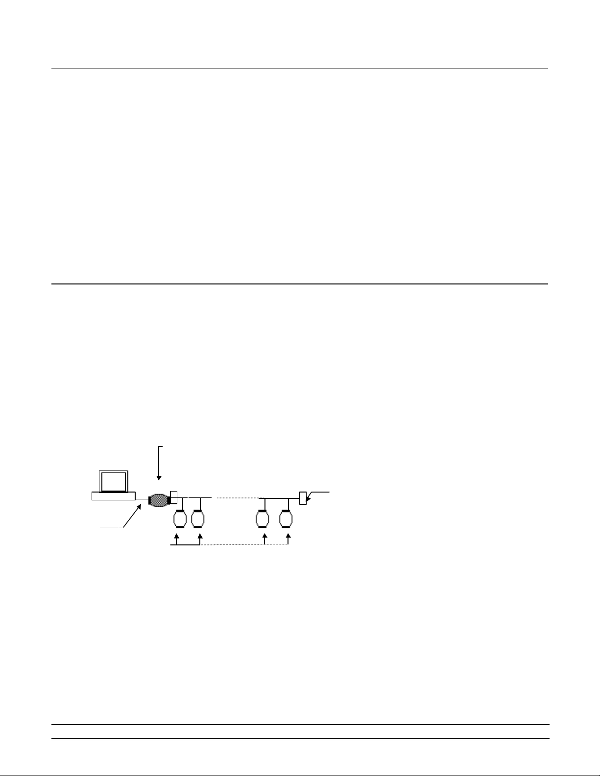
1.6 OMR RS-485 Network Configurations
OMR-6000 series is designed under RS-485 multi-drop network architecture. Up to 256 OMR modules can be
controlled in a multi-drop network. The limit of 256 is due to command code. The network can be connected
by simple topology (Figure 1-1) or branch topology (Figure 1-2) or free topology (Figure 1-3).
The OMR -6520 and OMR -6510 are the two basic communication modules to construct a RS-485 network. The
OMR-6520 is a RS-232 to RS-485/RS-422 converter. The OMR -6520 is used to build a RS-485 port for the host
computer by converting standard RS -232 signal into RS-485 signal.
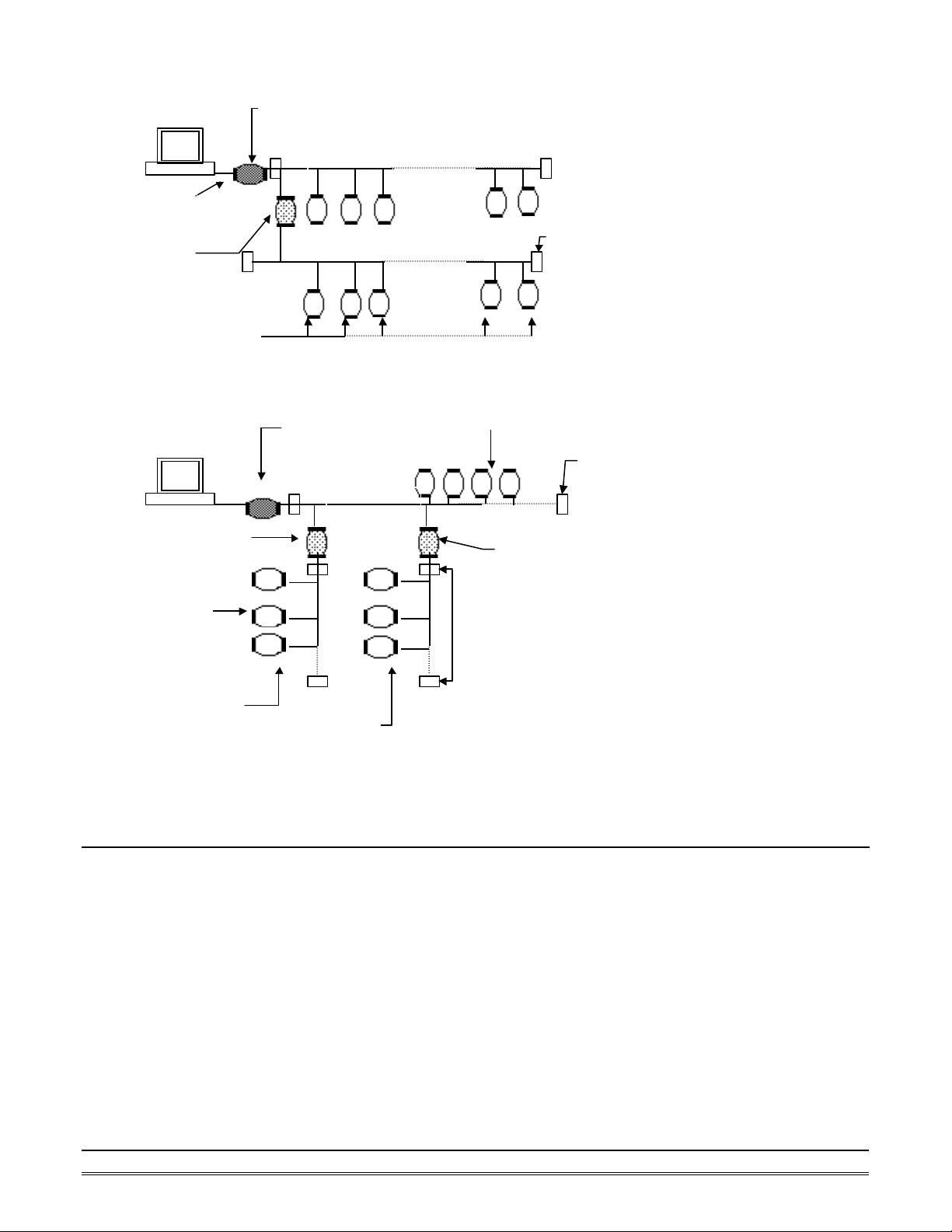
The OMR -6510 is the RS-485 signal repeater, which is used to extend or to lengthen the network distance. An
OMR bus can connect up to 256 modules, each segment is up to 128 modules. Whenever the numbers of the
modules excess 128, the repeater should be used. In addition, the length of a standard RS -485 bus is up to
4000 feet, the repeater should be used whenever the length of a signal bus is more than 4000 feet.
Host
RS-232
OMR Modules
ND-6520
OMR-6520
RS-232/RS-485
RS-232 to RS-485/RS-422
RS-485 bus
Figure 1-1 Simple Topology
1-4 Introduction
Page 7
Converter
Converter
Repeater
Terminator
Terminat
Terminat
Host
RS-232
OMR-651
0
Host
OMR Modules
OMR I/O modules
OMR Modules
OMR-6510
OMR-6520
RS-232 to RS-485/RS-422
RS-485 bus
RS-485 bus
Figure 1-2 Branch Topology
OMR-6520
RS-232 to RS-485/RS-422
OMR I/O modules
RS-485 bus
Figure 1-3 Free Topology
OMR Modules
OMR-6510
Repeater
1.7 Constructing a OMR Network
Go through the following steps, the user can construct an OMR network easily.
1. Setup an OMR-6520.
2. Connect the host computer with the OMR-6520.
3. Setup one or more OMR-6510 if necessary.
4. Connect the OMR-6510 to extend to RS -485 bus if necessary.
5. Install the OMR utility software from disk.
6. Initialize the brand-new OMR modules.
7. Add the new OMR modules into RS -485 network.
Refer to chapter 2 for executing step 1 and 2. Refer to chapter 3 for executing step 3, 4 and for understanding
the time to install OMR -6510. The knowledge about the software for operating the OMR is in chapter 5. For
executing the step 6 and step 7, refer to chapter 4.
Introduction 1-5
Page 8
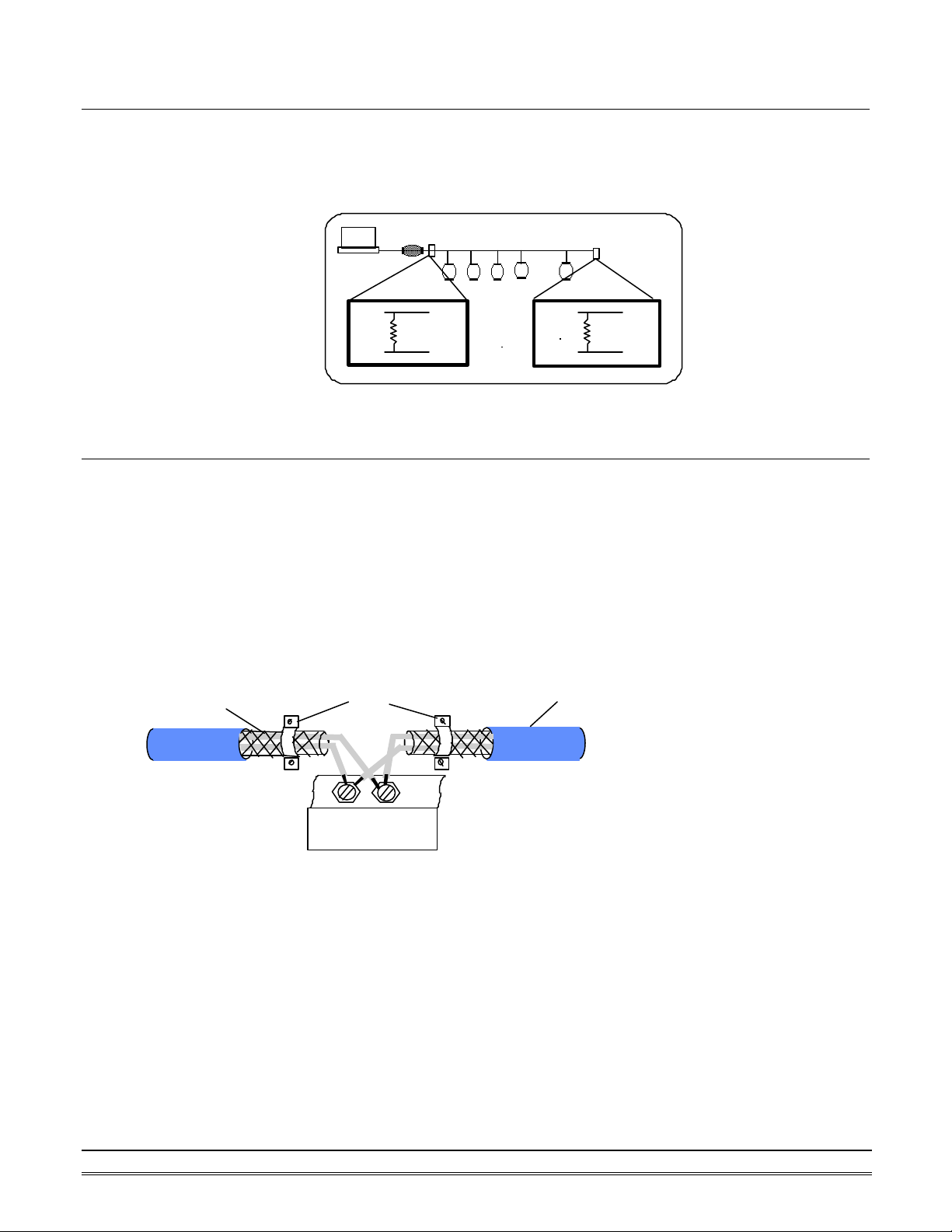
1.8 Termination Bus
In order to avoid signal reflections on the bus, each bus segment has to be blanked off at its physical beginning
and at its end with the characteristic impedance. A termination resister (Rt) is installed for this purpose. The Rt
value - 120Ω ± 2% is recommended, and the detailed connection of Rt can be referred from the “Terminator
Connection” diagram below.
Host
1.9. Shielding
In case of increased interference, a shielded bus cables is recommended to use for wiring between module and
modules. In addition, a shielding also should be done for the cable of power supply and for the signal cables.
Some experiences and recommendations are concerning for shield connection.
1. The shield should be connected with protective earthing at each bus connection.
2. The shield should be applied additionally several times along the course of the cable.
3. The Computer should be applied the shield directly to the appliance or to separate shield rails.
braided shield
Data+
120 ohms
Data-
Terminator Connection
EarthingPoint
Data+
120 ohms
Data-
Isolation
RS-485 Connection
1-6 Introduction
DA
TA
+
DA
TA
-
OMR-Module
Page 9

Response :
Response :
1.10. How to Calculate Checksum Value
Format of OM R Commands
(LeadingCode)(Addr)(Command)(Data)[Checksum]<CR>
When checksum is enable then [Checksum] is needed, it is
2-character.
[Checksum] = ((LeadingCode)+(Addr)+(Command)+(Data)) MOD 0x100
Example 1: checksum is disable
User Command : $012<CR>
!01400600
Example 2: checksum is enable
User Command : $012B7<CR>
!01400600AC
‘$’ = 0x24 ‘0’ = 0x30 ‘1’ = 0x31 ‘2’ = 0x30
B7 = ( 0x24 + 0x30 + 0x31 + 0x32 ) MOD 0x100
‘!’ = 0x24 ‘0’ = 0x30 ‘1’ = 0x31 ‘4’ = 0x34
‘6’ = 0x36
AC = ( 0x24 + 0x30 + 0x31 + 0x34 + 0x30 + 0x30 + 0x36 + 0x30 + 0x30 ) MOD 0x100
Introduction 1-7
Page 10

Page 11

2. OMR-6520
2.1. Overview
What is OMR-6520 ?
OMR-6520 is a RS -232 to RS-422/RS-485 converter, it converts the RS -232 signal to the RS-422/RS-485
signals. The OMR -6520 can be considered as an extension RS-422/RS-485 serial port for the host computer.
A standard 9-pin D-type connector is used to connect the host computer and the OMR-6520. Hence, the
OMR-6520 can connect with all kinds the PC, IPC or Notebook PC, which install a standard RS-232 interface.
Features of OMR-6520
• RS-422/RS-485 transceiver
• Differential 2-wire half-duplex RS -485
• Easily setup and installation
• Auto direction flow control
• Maximum 128 OMR on a bus without using repeaters
• Maximum 256 addressable OMR modules
• High transfer speed
• High isolation voltage
• Lower power consumption
OMR-6520 2-1
Page 12

Specifications of OMR-6520
² Input
• Interface : standard RS -232 9 pin female D-type connector
• Speed (bps) : 1200(115.2K1), 2400, 4800, 9600, 19.2K,
38.4K, RTS
• Data Format : 9 bits, 10 bits, 11 bits, or 12 bits
² Output
• Interface : RS-485, differential, 2 half-duplex wires
RS-422, differential, 4 full-duplex wires
• Speed (bps) : 1200(115.2K1), 2400, 4800, 9600, 19.2K,
38.4K, RTS
• Max RS -485 network bus distance : 4000 ft. (1200m)
² Isolation
• Isolation voltage : 5000 Vrms(between RS -422/RS-485
network and host computer)
² Bus
• Max loading : 128 OMRs on a RS -485 network
• Max modules : 256 OMRs with one OMR-6510 repeater
² Power
• Power Supply : +10V to +30V
• Power Consumption : 0.95 W
Note 1: 115.2K is supported by version A1.2 or later.
2-2 OMR-6520
Page 13

SW1: ON
SW2: ON
SW7: ON
A Look at OMR-6520 & Pin Assignment
(RS-232 IN)
RS-232 to RS-485
OMR-6520
Switch Position
SW4: ON
SW5: ON
SW6: ON
/RS-422Converter
Baud Rate
RTS CTRL
115.2K bps
2400 bps
4800 bps
9600 bps
19.2K bps
38.4K bps
(Y) DATA+
(G)DATA-
TX+
TX-
RX+
TX-
(R)+Vs
(B)GND
OMR-6520 2-3
Page 14

Pin Definitions
Pin # Signal Name Description
1 (Y)DATA+ RS-485 transmission line, positive
2 (G)DATA- RS-485 transmission line, negative
4 TX+ RS-422 transmission line, positive
5 TX - RS-422 transmission line, negative
6 RX+ RS-422 receiving line, positive
7 RX - RS-422 receiving line, negative
9 (R)+VS OMR power supply, +10V~+30V
10 (B)GND OMR ground
-- RS-232 IN 9-pin RS -232 connector
Connection Between Host and OMR-6520
Host RS -232
RTS ’
GND •
TXD Ž
RXD •
Host
Computer
RS-232
OMR-6520 RS-232
‡ RTS
… GND
ƒ TXD
‚ RXD
OMR-6520
RS-232/RS-485
DATA +
DATA -
+Vs GND
2-4 OMR-6520
Page 15

Power Regulator
& Filter
Power Input
+10V ~ +30V
+5V
GND
Isolation +5V
Isolation GND
DC to DC
Converter
TXD
RXD
RTS
GND
Receiver
RS-232
/ Driver
SW1
Switching
Communication
Controller
PTC : Positive Temperature Coefficient
Receiver/Driver
Data+
Data-
Rx+
Rx-
Tx+
Tx-
Functional Block Diagram
RS-422/RS-485
Opto-Isolation
Communication
Direction Control
TVS : Transient Voltage Suppresser
OMR-6520 2-5
Page 16

2.2. Setup
Objective of Setup
In normal condition, it is not necessary to setup the OMR-6520. The default configuration of this
communication module is 9600 bps and data format of 8 data bits with 1 start bit, 1 stop bit, and no parity
check. Note that the data format is reserved to be compatible with other brand‘s communication port; it should
not be modified if only OMR is used in a system. The baud rate can be configured according applications’
requirement.
Setup Equipments
Only screwdriver is used to open the case. Software, power supply, and wiring are not necessary.
Setup Procedure
Only hardware switch setting can be setup in OMR-6520. The user can set the speed of the serial interface
(RS-232 and RS-422/RS-485), and the serial data format. The speed and the data format on the whole RS-485
network must be identity otherwise the communication will be not correct.
To setup the OMR -6520, use the screwdriver to open the case, then change the switch setting. The new setting
is available after power on. The case must be put back and locked carefully. Note that do not scratch the
surface of the circuit while setting up, otherwise the surface coating or even the circuits will be damaged.
Default Setting
• 9600 baud rate
• 10 bits series data format : one start bit, eight data bits, one stop bit, no parity check
SW1 Setting
SW1 Default Setting (9600 bps)SW1 Default Setting (9600 bps)
ON
11 22 33 44 55 66 77
OFF
1 2 3 4 5 6 7 Baud Rate
ON OFF OFF OFF OFF OFF OFF RTS Control
OFF ON OFF OFF OFF OFF OFF 1200 or 115.2k1 bps
OFF OFF ON OFF OFF OFF OFF 2400 bps
OFF OFF OFF ON OFF OFF OFF 4800 bps
OFF OFF OFF OFF ON OFF OFF 9600 bps
OFF OFF OFF OFF OFF ON OFF 19200 bps
OFF OFF OFF OFF OFF OFF ON 38400 bps
Note 1: 115.2kbps is supported by version A1.2 or later.
2-6 OMR-6520
Page 17

ON
1
2
Data Bits : 8
Stop Bits : 1
SW2 Setting
SW2 Default Setting
Start Bits : 1
Parity : None
1 2 Start Bit Data Bits Stop Bit Parity Packet Data Bits
1 7 1 0 OFF OFF
9
1 6 1 1
1 8 1 0 OFF ON
10
1 7 1 1
1 9 1 0 ON OFF
11
1 8 1 1
1 10 1 0 ON ON
12
1 9 1 1
2.3. Installation
Software Utility
Software is not necessary for this module.
Equipments for Installation
A host computer wit h RS-232 port
RS-232 cable (DB-9 female)
DC Power supply (+10V~+30V) (NDP-243u is recommended)
Wires (shielded and grounded is recommended)
Installation Procedure
1. Make sure the host computer is power off.
2. Use RS-232 cable to connect OMR-6520 with host comp uter.
3. Wire the power supply to OMR. Note that the power supply should meet the specification.
4. Wire other OMRs.
Application Wiring
The Figure 2-1 shows the application wiring of OMR-6520.
Host
Computer
Local Power Supply
+10 V to +30 V
+Vs GND
RS-232
RS-232/RS-485
DATA +
DATA -
+Vs GND
OMR moduleOMR-6520
+ DATA
- DATA
+Vs GND
OMR-6520 2-7
Page 18

2.4 Programming
The OMR-6520 is a communication module, it is not necessary to be programmed.
Figure 2-1 Application wiring of OMR-6520
2-8 OMR-6520
Page 19

3. OMR-6510
3.1. Overview
What is OMR-6510 ?
The OMR-6510 is the RS -422/RS-485 signal repeater which is used to extend or to lengthen the network
distance. A OMR bus can connect up to 128 modules. The repeater should be used when the numbers of the
modules excess 128. In addition, the repeater should also be used when the length of a signal bus is more
than 4000 feet.
Features of OMR-6510
• RS-422/RS-485 signal transceiver & repeater
• Bi-directions signal transmission for both RS -422/RS-485 ports
• Automatic transmission direction control
• Easily setup and installation
• Maximum 128 OMR on a bus
• Maximum 256 addressable OMR modules
• High transfer speed
• Surge protection
• Lower power consumption
Specifications of OMR-6510
² Input / Output
• Interface : RS-485, differential 2 half-duplex wires
RS-422, differential, 4 full-duplex wires
• Speed (bps) : 1200(115.2K1), 2400, 4800, 9600, 19.2K, 38.4K
• Data Format : 9 bits, 10 bits, 11 bits, or 12 bits
• Max RS -485 network bus distance : 4000 ft. (1200m)
Note 1: 115.2k is supported by version A1.2 or later.
² Bus
• Max Loading : 128 OMRs on a bus
² Power
• DC Power Supply : +10V to +30V
• Power Consumption : 0.9 W
A Look at OMR-6510 & Pin Assignment
OMR-6510 3-1
Page 20

20
DATA+ (Y)
DATA- (G)
OMR-6510
Switch Position Baud Rate
SW1-1: ON 115.2K bps
SW1-2: ON
SW1-3: ON
SW1-4: ON
SW1-5: ON
SW1-6: ON
1
(Y)DATA+
(G)DATA-
Tx+
Tx+
Tx-
RS-422/RS-485
Repeapter
2400 bps
4800 bps
9600 bps
19.2 K bps
38.4 K bps
Tx-
Rx+
Rx+
Rx-
RX-
(R)+Vs
11
(B)GND
10
3-2 OMR-6510
Page 21

Pin Definitions
Pin # Signal Name Description
1 (Y)DATA+ RS-485 transmission line, positive
2 (G)DATA- RS-485 transmission line, negative
4 TXIN+ RS-422 transmission input line, positive
5 TXIN- RS-422 transmission input line, negative
6 RXOUT+ RS-422 receiving output line, positive
7 RXOUT - RS-422 receiving output line, negative
9 (R)+VS OMR power supply, +10V~+30V
10 (B)GND OMR ground
14 RXIN- RS-422 receiving input line, negative
15 RXIN+ RS-422 receiving input line, positive
16 TXOUT - RS-422 transmission output line, negative
17 TXOUT+ RS-422 transmission output line, positive
19 (G)DATA- RS-485 transmission line, negative
20 (Y)DATA+ RS-485 transmission line, positive
OMR-6510 3-3
Page 22

Power Regulator
& Filter
Power Input
+10V ~ +30V
+5V
GND
TVS : Transient Voltage Suppresser
PTC : Positive Temperature Coefficient
Data+
Data-
Rx+
Rx-
Tx+
Tx-
SW1
Communication
Switching
Controller
Communication
Data+
Data-
Rx+
Rx-
Tx+
Tx-
OMR-6510 Functional Block Diagram
RS-422/RS-485
Receiver/Driver
RS-422/RS-485
Receiver/Driver
Direction
Control
3-4 OMR-6510
Page 23

3.2. Setup
Objective of Setup
In normal condition, it only needs to setup the OMR-6510 when the OMR bus with more than 128 modules or
the distance exceeds 4000 feet long. The default configuration of this communication module is 9600 bps and
data format of 8 data bits with 1 start bit, 1 stop bit, and no parity check. Note that the data format is reserved
to be compatible with other brand‘s communication port, it should not be modified if only OMR is used in a
system. The baud rate can be configured according user’s requirement.
Setup Equipments
Only screw driver is used to open the case. Software, power supply, and wiring are not necessary.
Setup Procedure
Only hardware switch setting can be setup in OMR-6510. The user can set the speed and the data format of
the RS-422/RS-485 interface. The speed and the data format on the whole network must be identity otherwise
the communication may be not correct.
To setup the OMR-6510, use the screw driver to open the case, then change the switch setting. The new
setting is available after power on. The case must be put back and locked carefully. Note that do not scratch
the surface of the circuit while setting up, otherwise the surface coating or even the circuits will be damaged.
Default Setting
• 9600 Baud rate
• 10 bits serial data format : one start bit, eight data bits, one stop bit, no parity check
SW1 Setting
SW1 Default Setting (9600 bps)SW1 Default Setting (9600 bps)
ON
11 22 33 44 55 66
OFF
1 2 3 4 5 6 Baud Rate
ON OFF OFF OFF OFF OFF 1200 or 115.2k1 bps
OFF ON OFF OFF OFF OFF 2400 bps
OFF OFF ON OFF OFF OFF 4800 bps
OFF OFF OFF ON OFF OFF 9600 bps
OFF OFF OFF OFF ON OFF 19200 bps
OFF OFF OFF OFF OFF ON 38400 bps
Note 1: 115.2kbps is supported by version A1.2 or later.
SW2 Setting
OMR-6510 3-5
Page 24

ON12
Start Bits : 1
Data Bits : 8
Stop Bits : 1
Parity : None
SW2 Default Setting
1 2 Start Bit Data Bits Stop Bit Parity Packet Data Bits
1 7 1 0 OFF OFF
9
1 6 1 1
1 8 1 0 OFF ON
10
1 7 1 1
1 9 1 0 ON OFF
11
1 8 1 1
1 10 1 0 ON ON
12
1 9 1 1
3.3 Installation
Software Utility
Software is not necessary.
Equipments for Installation
A 2-wire RS -485 network or 4-wire RS-422 network.
DC Power supply (+10V~+30V)
Wires
Installation Procedure
1. Make sure the original RS -422/RS-485 network is power off.
2. Wire the power supply to OMR-6510. Note that the power supply should meet the specification.
3. Wire other OMRs to the extend RS -485 bus.
3-6 OMR-6510
Page 25

+Vs GND
module
Application Wiring
OMR
module
DATA +
DATA -
+Vs GND
Local Power Supply
+10 V to +30 V
OMR-6510
Repeater
+DATA DATA+
-DATA DATA-
+Vs GND
OMR
+ DATA
- DATA
+Vs GND
Figure 3-1 OMR-6510 wiring.
3.4 Programming
The OMR-6510 is a communication module, it is not necessary to be programmed
OMR-6510 3-7
Page 26

Page 27

4. Install a Brand New OMR
4.1 Initialize a Brand-New OMR
Objective of Initializing a Brand-New OMR
All OMR modules. except OMR-6520 and OMR-6510, in a RS -485 network must have an unique address ID,
however, every brand-new OMR has a factory default setting as following:
• Baud rate is 9600 bps.
• Address ID is 01.
• Checksum is disable.
• Host watchdog timer is disable.
Therefore, to configure the brand-new OMR before using is necessary, otherwise the address ID will conflict
with others. The baud rate may also be changed according to user‘s requirements.
The following initialization procedures are need not only for a brand-new module, but also for a installed OMR
module. When the user want to change the setting, the initialization procedure can also be used.
Initial State
The OMR I/O modules must be set a Initial State when you want to change the default settings of the modules,
such as the ID address, baud rate, check-sum status etc. All OMR I/O modules have an special pin labeled as
Default*. “ The module will be set as Initial State if the Default* pin is shorted to ground.” Under this state,
the default configuration is set as following:
• Address ID is 00.
• Baud rate is 9600 bps.
• Checksum is disable.
• Host watchdog timer is disable.
In itialization Equipments
• Host computer with an RS -232 port.
• An installed RS -485 module (OMR-6520) with 9600 baud rate.
• The brand new OMR module
• DC Power supply (+10 to +30 VDC) for OMR modules
• A OMR-6510 if the connection distance is more than 4000 ft.
Initialization Procedure A
-- As Baud rate is 9600 bps and check-sum is disable
1. Power off the host computer and the installed OMR-6520. Be suring the baud rate of the OMR-6520 is
9600 bps.
2. Connect a brand new OMR module with the RS -485. Refer to Figure 4.1 for detail wiring.
3. Power on the host computer.
4. Power on the power supply for OMR modules.
5. Use the OMR Administrating utility to configure the address ID, Baud rate and check-sum status of the
module.
Initialization Procedure B
-- As Baud rate is not 9600 bps or check-sum is not disable
1. Power off the host computer and the installed OMR-6520.
2. Connect a brand new OMR module with the RS -485. Refer to Figure 4.1 for detail wiring.
3. Configure the OMR-6520 to Baud rate 9600 bps.
4. Short the DEFAULT* pin of the brand-new module.
5. Power on the host computer.
Install a Brand -New OMR 4-1
Page 28

6. Power on the power supply for OMR modules.
7. Use the OMR Administrating utility to configure the address ID, Baud rate and check-sum status of the
module.
8. Power of the local power supply.
9. Disconnect the DEFAULT* pin.
10. Configure the OMR-6520 to desired Baud rate.
11. Power on the local power supply
12. Use OMR Administration utility to check the module‘s new setting.
4-2 Install a Brand -New OMR
Page 29

+Vs GND
Converter
Initialization Wiring
Host
Computer
RS-232
Local Power Supply
+10 V to +30 V
OMR-6520
RS-232/RS-485
DATA +
DATA -
+Vs GND
New
OMR
module
DATA+
DATA Default*
+Vs GND
Figure 4-1 Layout for Configuring the OMR module
4.2 Install a New OMR to a Existing Network
Equipments for Install a New Module
• A existing OMR network
• New OMR modules.
• DC Power supply (+10 to +30 VDC).
Installing Procedure
1. Configure the new OMR module according the initialization procedure in se ction 4.1.
2. The baud rate and check-sum status must be identity with the existing RS-485 network. The address ID must not
be conflict with other OMR modules.
3. Power off the OMR local power supply of the existing RS-485 network.
4. Power off the host computer.
5. Add the new module to the existing RS-485 network.
6. Power on the host computer.
7. Power on the OMR local power supply.
8. Use the OMR administration utility to check entire network.
Install a Brand -New OMR 4-3
Page 30

Page 31

5. Software Utility
5.1 Software Installation
1. Insert “ADLink All-in-one CD” into your CDROM driver.
2. Move cursor on OMR and click.
3. Move cursor on OMR 6000 Admin Utility and click.
4. Select the driver you want to install and follow the setup instructions on screen.
5.2 How to Execute the OMR Administration
What environment you needed?
1. At least one RS -232 communication port.
2. Microsoft Windows (version 3.1, 95/98/NT)
3. At least 2MB Hard Drive Space
4. A VGA monitor (optional)
5. Mouse (optional)
Execute the OMR Administration Utility
l Run “OMR Administration Utility” Icon.
Software Utility 5-1
Page 32

5.3 OMR Administration Function Overview
Default RS -232 Communication Port Setting.
l Communication Port : COM2
l Baud Rate : 9600
l Data Bits : 8
l Stop Bits : 1
l Parity : None
5.3.1 Change RS -232 Communication Port Setting.
Choose “Network -ComPort” to change setting.
5.3.2 Search all exist OMR modules
Choose “Network -Search” to search all exist OMR modules in the current RS-485 network.
You can change search addresses range from here.
5-2 Software Utility
Page 33

Terminal Emulation, user can input
Configuration :
Select one exist OMR module and
his module‘s
Monitor all the module’s function on the
5.3.3 Using Operations
Operation-Terminal :
Operation-
Operation-Monitor:
Operation-Diagnostic: Diagnostic module‘s function.
Operation-Calibration: Some A/D modules need do calibration
Operation-Model Number: Select Model Number
command and get response message.
select Configuration to do t
common and private setting .
network.
Term ICON for Operation-Terminal
You can remote control all moudles by directly using command mode, or testing your from this Terminal.
Software Utility 5-3
Page 34

Operation-Run Batch : Run batch command file in BATCH.CMD
user can edit this text file.
Operation-Step Batch : Run the batch command step by step.
Operation-Display Batch : Display content of BATCH.CMD
Operation-Repeat : Repeat one command n times
Diag ICON for Operation-Diagnostic
This dialog is different by different -fuction modules.
5-4 Software Utility
Page 35

Software Utility 5-5
Page 36

in the
Cal ICON for Operation-Calibration
This dialog is different by different -fuction modules.
5.3.4 Save and Print OMR modules’ information
File-Save : Save all exist OMR modules information as display as
listbox in the current RS -485 network.
File-Print : Print the OMR module information in the listbox.
File-Exit : Quit the OMR Administration Utility.
5-6 Software Utility
Page 37

5.3.5 Version Information
Help-About Version information
Software Utility 5-7
Page 38

5-8 Software Utility
Page 39

6. Troubleshooting and Maintenance
Preventive Maintain
• Periodic check for loose connection
ATTENTION: To avoid electircal shock or unintended operation of the module, remove incoming power before
checking connections.
Using the LED Indication
The LED provides status information on Modules operation. The troubleshooting about shows LED indicator. It
also shows how to use the LED to detect and correct common operating problems.
LED What it Means: What to do:
OFF 1. Module is not receiving input
power by loosing wiring.
ON(RED) 1. Normal receiving state. 1. No action required.
Flashing 1. Normal transmitting state. 1. No action required.
Other Malfunctions
Problem What it Means: What to do:
1.Check module wiring, cable
connections, and cable connections
on terminal block.
Do not
function
1.Loose wiring
2.Incorrect DIP switch setting
1. Check wiring and cable
connection
2. Check Baudrate and
data packet setting of
the DIP switch.
Troubleshooting and Maintenance 6-1
 Loading...