

Page 1
M-3578 for OMR-6080
Counter/Frequency
Input Module
Page 2

Page 3

Contents
1. Introduction ..............................................................................1-1
1. 1. About the OMR Counter/Frequency Modules..................................1-1
1. 2. Overview of OMR -6080........................................................................1-1
What is OMR-6080? .......................................................... 1-1
Features of OMR-6080....................................................... 1-2
Specifications of OMR-6080 ............................................... 1-2
Pin Definitions of OMR-6080 .............................................. 1-4
A Look at OMR-6080 & Pin Assignment ..............................1-5
Functional Block Diagram of OMR-6080.............................. 1-6
2. Initialization & Installation .........................................................2-1
2. 1. Software Installation.............................................................................2-1
2. 2. Initializing a Brand-New Module.......................................................2-2
Objective of Initializing a Brand -New OMR..........................2-2
Default State..................................................................... 2-2
Initialization Equipment ...................................................... 2-3
Initialization Procedure....................................................... 2-3
Initialization Wiring............................................................. 2-3
2. 3. Install a New OMR to a Existing Network........................................2-4
Equipments for Install a New Module .................................. 2-4
Installing Procedures ......................................................... 2-4
2. 4. Application Wiring for OMR-6080 ..................................................... 2-5
Non-isolated Input ..............................................................2-5
Photo-isolated Input ........................................................... 2-5
3. Command Set ............................................................................3-1
3. 1. Command and Response......................................................................3-1
Introduction ....................................................................... 3-1
Document Conventions ...................................................... 3-1
Format of OMR Commands................................................ 3-2
Response of OMR Commands ........................................... 3-3
3. 2. Summary of Command Set...................................................................3-4
3. 3. Set Configuration...................................................................................3-7
3. 4. Read Configuration.............................................................................3-10
3. 5. Read Module Name.............................................................................3-11
3. 6. Read Firmware Version......................................................................3-12
3. 7. Set Input Mode.....................................................................................3-13
3. 8. Read Input Mode.................................................................................3-14
3. 9. Read Counter/Frequency Value in HEX Format............................3-15
3. 10. Read Counter/Frequency Value in DEC Format ...........................3-16
3. 11. Set Gate Mode......................................................................................3-17
3. 12. Read Gate Mode..................................................................................3-18
3. 13. Set Maximum Counter Value.............................................................3-19
3. 14. Read Maximum Counter Value ..........................................................3-19
3. 15. Set Initial Count Value........................................................................3-21
3. 16. Read Initial Count Value....................................................................3-22
3. 17. Start/Stop Counter...............................................................................3-23
3. 18. Read Start/Stop Counter Status.........................................................3-24
3. 19. Clear Counter .......................................................................................3-25
3. 20. Read then Clear Overflow Flag........................................................3-26
3. 21. Enable/Disable Digital Filter ............................................................3-28
3. 22. Read Filter Status ................................................................................3-29
3. 23. Set Minimum Input Signal Width at High Level.............................3-30
3. 24. Read Minimum Input Signal Width at High Level.........................3-31
3. 25. Set Minimum Input Signal Width at Low Level..............................3-32
3. 26. Read Minimum Input Signal Width at Low Level..........................3-33
Contents i
Page 4

3. 27. Set TTL In put High Trigger Level.....................................................3-34
3. 28. Read TTL Input High Trigger Level.................................................3-35
3. 29. Set TTL Input Low Trigger Level......................................................3-36
3. 30. Read TTL Input Low Trigger Level..................................................3-37
3. 31. Enable Alarm ........................................................................................3-38
3. 32. Disable Alarm......................................................................................3-39
3. 33. Set Alarm Limit Value of Counter 0..................................................3-40
3. 34. Set Alarm Limit Value of Counter 1..................................................3-41
3. 35. Read Alarm Limit Value of Counter 0..............................................3-42
3. 36. Read Alarm Limit Value of Counter 1..............................................3-43
3. 37. Set Digital Output Values...................................................................3-44
3. 38. Read Digital Output and Alarm Status ............................................3-45
3. 39. Read Command Leading Code Setting............................................3-47
3. 40. Change Command Leading Code Setting.......................................3-48
3. 41. Set Host Watchdog Timer & Safety Value ........................................3-50
3. 42. Read Host Watchdog Timer & Safety Value....................................3-51
3. 43. Host is OK.............................................................................................3-52
ii Contents
Page 5

1. Introduction
1. 1. About the OMR Counter/Frequency Modules
The OMR provides a counter / frequency input module, which has two 32 bit counter input channels with built in
programmable timer for frequency measure function.
OMR-6080: counter/frequency input module with digital output.
1. 2. Overview of OMR-6080
What is OMR-6080?
OMR-6080 is a counter / frequency input module. It has two 32-bit counter input channels with built in
programmable timer for frequency measurement and supports both photo isolated and non-isolated input
mode. The maximum counting value is 4,294,967,295 for counter input channel and the frequency-input
range is from 1 Hz to 100 kHz. A programmable digital filter can be enable for both high and low level
minimum signal width to reduce noise spike. Besides the programmable threshold for non -isolated input can
further reject noise on the input signal level.
The module provides the counter comparator or the alarm function. The alarm limit of two counters can be
set independently by programming. The alarm status can be send to digital output channels if this function is
ON. The supervisor of a factory can ‘see’ or ‘hear’ the alarm if the digital output channel control a real alarm
device. The two digital output channel can be set for general purpose used if the alarm is disable. For
example, connecting relay devices to DO channels, the OMR-6080 can be used to control the high power
devices.
Introduction 1-1
Page 6

Features of OMR-6080
• Two 32 bit counter / frequency input channel
• Two digital output channels of open collector type
• 5000 Vrms isolation voltage for isolated input mode
• External gate control for counter input
• Alarm function with alarm output
• Programmable digital filter for noise rejection
• Programmable threshold setting of trigger level for non-isolated input mode
• Programmable host watchdog timer for host failure protection
• Internal watchdog timer for device failure protection
• Easy programming by software
• Easy installation and wiring
Specifications of OMR-6080
² Interface
• Interface : RS -485, 2 wires
• Speed (bps) : 1200, 2400, 4800, 9600, 19.2K, 38.4K
² Counter Input
• Two independent 32 bit counters
• Input frequency: 100 kHz max.
• Input mode: Isolated or non-isolated
• Isolated input level:
• Isolation voltage: 5000 Vrms
• Non-isolated input level (programmable threshold):
• Input pulse width > 5 µsec.
• Programmable digital noise filter:
• Alarm comparator on each counter
Logic level 0: +1V max.
Logic level 1: +3.5V to +30V
Logic level 0: 0 to +5V (default = 0.8V)
Logic level 1: 0 to +5V (default = 2.4V)
4 µsec. to 1.02 msec.
1-2 Introduction
Page 7

² Frequency measurement Input
• Range: 1 Hz to 100 kHz
• Programmable built in gate time: 0.1/1.0 sec.
² Digital Output
• Channels: Two open collector to 30 V, 30 mA max. load
² Watchdog Function
• Module internal watchdog timer : 150 ms
• Power failure threshold : 4.65 V
• Safety value : 2 digital output channels
• Host programmable watchdog: 100 ms ~ 25.500 sec.
² Power
• Power supply : +10V to +30V
• Power consumption: 2.0W
Introduction 1-3
Page 8

Pin Definitions of OMR-6080
Pin # Signal Name Description
1 IN0 Non-isolated input of counter 0
2 GATE0 External gate control of counter 0
3 GND Ground for non-isolated input
4 IN1 Non-isolated input of counter 1
5 GATE1 External gate control of counter 1
6 DEFAULT* Initial state setting
7 (Y) DATA+ RS-485 series signal, positive
8 (G) DATA- RS-485 series signal, negative
9 (R) +Vs Power supply, +10V~+30V
10 (B) GND Ground
11 GATE1 - Differential negative external gate
control of counter 1
12 GATE1+ Differential positive external gate
control of counter 1
13 IN1- Differential negative input of counter
1
14 IN1+ Differential positive input of counter 1
15 GATE0 - Differential negative external gate
control of counter 0
16 GATE0+ Differential positive external gate
control of counter 0
17 IN0- Differential negative input of counter
0
18 IN0+ Differential positive input of counter 0
19 DO0 Digital output of channel 0 or counter
0 alarm output
20 DO1 Digital output of channel 1 or counter
1 alarm output
1-4 Introduction
Page 9
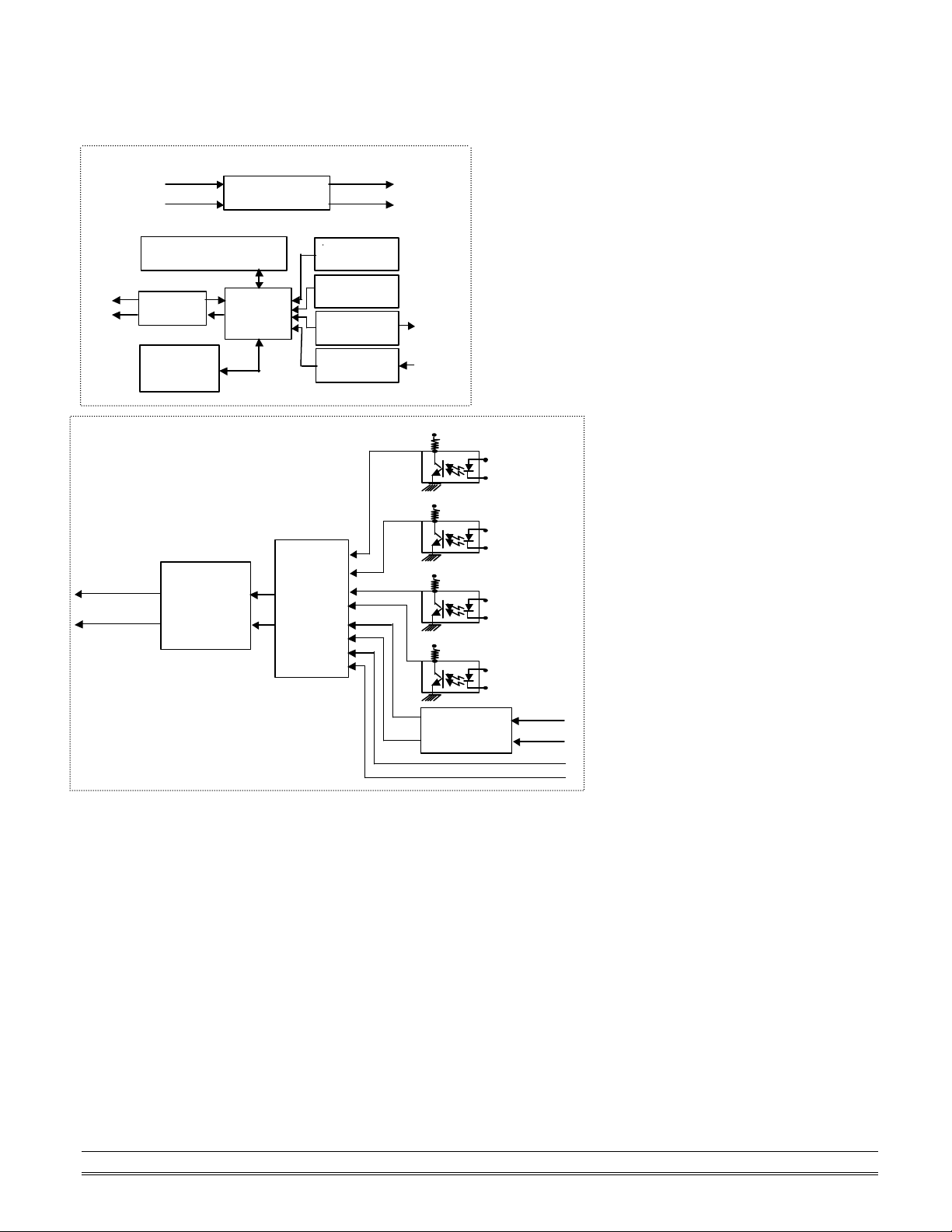
A Look at OMR-6080 & Pin Assignment
Power Input
Power
Regulator & Filter
RS-485
EEPROM
Safe Value
Watchdog/Power Failure
1-bit
2-bits
Digital Output
DO0
DO1
Default*
+5V
+5V
Programmable
+5V
+5V
Counter 1
+10V ~ +30V
Data +
Data -
Counter 0
Supervisor
Rec/Drv
Config Data
Programmable
Digital
Noise
Filter
Micro
Processor
Counter 0
Counter 1
Digital Input
PHTO/TTL
Input
Select and
GATE
Control
+ 5V
GND
Pin
GATE0+
GATE0-
GATE1+
GATE1-
CH0+
CH0-
CH1+
CH1-
CH1 (TTL)
Threshold
Voltage
CH1 (TTL)
GATE0 (TTL)
GATE1 (TTL)
Introduction 1-5
Page 10
Functional Block Diagram of OMR-6080
GATE1-
10
Input Module
IN0
CODE
SIGNAL
20
DO1
DO0
IN0+
OMR-6080
IN0-
GATE0+
GATE0-
Counter/Frequency
IN1+
IN1-
GATE1+
11
50 COUNTER
51 FREQUENCY
GATE0
1
GND
IN1
GATE1
DEFAULT*
DATA+
DATA-
+Vs
GND
1-6 Introduction
Page 11

2. Initialization & Installation
2. 1. Software Installation
1. If you had installed “OMR Administration” then skip other steps.
2. Backup your software diskette
3. Insert “OMR Administration” diskette into floppy drive A:
4. Change drive to A:
5. Installation command syntax
INSTALL drive:
Drive name is C to Z.
Example 1: install to drive C:
A:\> INSTALL C:
Example 2: install to drive F:
A:\> INSTALL F:
6. OMR Administration Utility will be installed in the directory C: \OMR
Initialization & Installation 2-1
Page 12

2. 2. Initializing a Brand-New Module
Objective of Initializing a Brand-New OMR
All OMR modules except OMR-6520 and OMR-6510, in an RS -485 network must have a unique address ID,
however, every brand-new OMR has a factory default setting as following:
• Address ID is 01.
• Baud rate is 9600 bps
• Check-sum disable
• Host Watchdog timer is disable
Therefore, to configure the brand-new OMR before using is necessary, otherwise the address ID will be
conflict with others modules because the ID of new modules are identity. The baud rate may a lso be changed
according to user‘s requirements.
The following sections show how to initialize a brand-new module, which is applicable for initializing
OMR-6080.
Default State
The OMR I/O modules must be set at Default State when you want to change the default settings, such as
the baud rate and check-sum status etc. All OMR I/O modules have an special pin labeled as DEFAULT*.
The module will be in Default State if the DEFAULT* pin is shorted to ground when power ON. Under this
state, the default configuration is set as following:
• Address ID is 00.
• Baud rate is 9600 bps.
• Check-sum is disable.
Therefore, the communication between host and the module can be easily set as the same default
configuration, the initialization of a module will be possible no matter what configuration is set under
operating state.
2-2 Initialization & Installation
Page 13
Initialization Equipment
Local Power Supply
New OMR
OMR-6520
• Host computer with an RS -232 port.
• An installed RS -485 module (OMR-6520) with 9600 baud rate.
• The brand new OMR module
• Power supply (+10 to +30 VDC) for OMR modules
• Administration utility software
Initialization Procedure
1. Power off the host computer and the installed OMR-6520. Be sure of the baud rate of the OMR-6520 is
2. Connect a brand new OMR module with the RS -485. Set the module in Default State by shorting the
3. Power on the host computer.
4. Power on the power supply for OMR modules.
5. Use the OMR Administration utility to configure the address ID, Baud rate and check-sum status of the
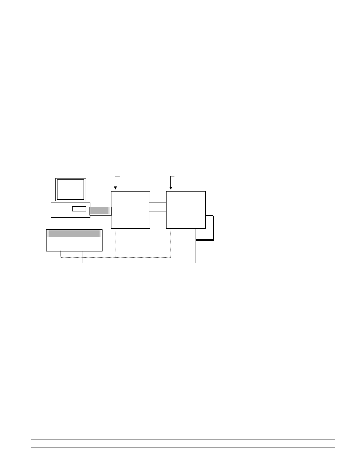
Initialization Wiring
+10 V to +30 V
+Vs GND
9600 bps.
DEFAULT* pin. Refer to Figure 2.1 for detailed wiring.
module.
Host
Computer
RS-232
RS-232/RS-485
Converter
DATA +
DATA -
+Vs GND
module
DATA+
DATA Default*
+Vs GND
Figure 2-1 Layout for Initialization the OMR module
Initialization & Installation 2-3
Page 14

2. 3. Install a New OMR to a Existing Network
Equipments for Install a New Module
• A existing OMR network
• New OMR modules.
• Power supply (+10 to +30 VDC).
Installing Procedures
1. Configure the new OMR module according to the initialization procedures in section 2.2.
2. The baud rate and check-sum status of the new module must be identity with the existing RS -485
network. The address ID must not be conflict with other OMR modules on the network.
3. Power off the OMR power supply of the existing RS -485 network.
4. Power off the host computer.
5. Wire the power lines for the new OMR with the existing network. Be careful about the signal polarity as
wiring.
6. Wire the RS -485 data lines for the new OMR with the existing network. Be careful about the signal
polarity as wiring.
7. Wire to the input or output devices. Refer to section 2.4 for illustrations.
8. Power on the host computer.
9. Power on the OMR local power supply.
10. Use the OMR administration utility to check entire network.
2-4 Initialization & Installation
Page 15
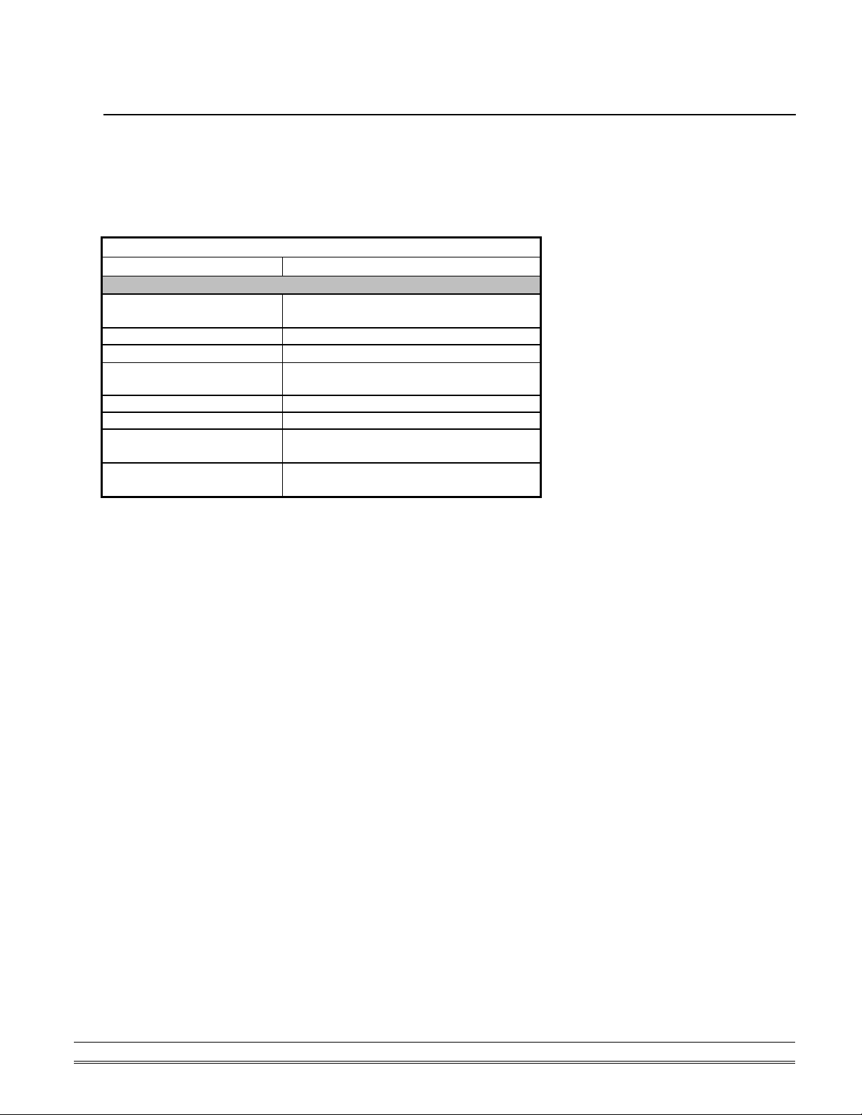
IN1+
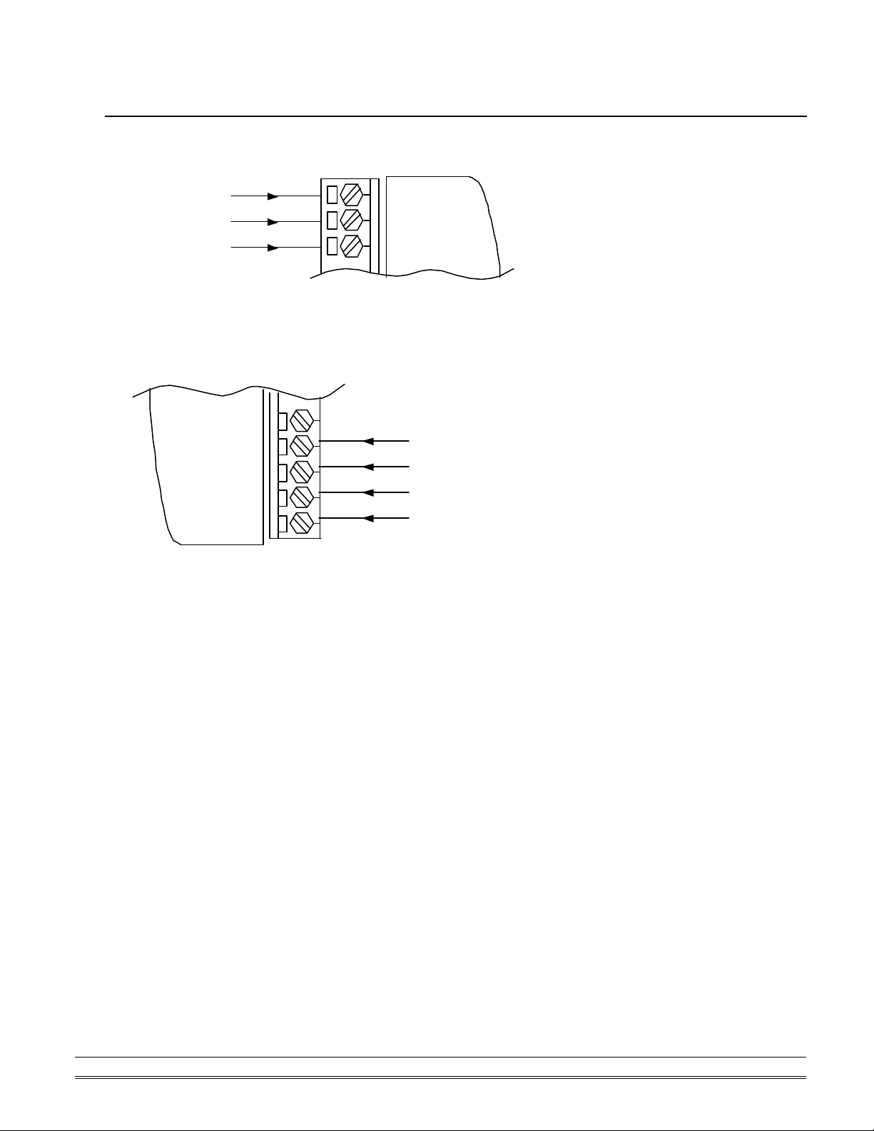
2. 4. Application Wiring for OMR-6080
Non-isolated Input
Counter Input
Gate Control
GND
Photo-isolated Input
IN1-
GATE1+
GATE1-
11
+
+
-
IN0 1
+GATE0
D.GND
Counter Input
Gate Control
Initialization & Installation 2-5
Page 16

Page 17

3. Command Set
3. 1. Command and Response
Introduction
The OMR command is composed by numbers of characteristics, including the leading code, address ID, the
variables, the optional check-sum bytes, and a carriage return to indicate the end of a command. The host
computer can only command only one OMR module except those synchronized commands with wildcard
address “**”. The OMR may or may not give response to the command. The host should check the response
to handshake with the modules.
Document Conventions
The following syntax conventions describes the OMR commands in this manual.
(Leading Code) Leading Code is the first characteristic of the
OMR command. All OMR commands need a
command leading code, such as %,$,#,@,...etc.
1- character
(Addr) Module’s address ID, the value is in the range of
00 - FF (Hex). 2- character
(Command
Variable)
[Data] Some commands need additional data.
[Checksum] Checksum in brackets indicate optional
< > Identifies a control code character, such as
Command codes or value of variables.
Variable length
Variable length
parameter, only checksum is enable then this
field is required. 2- character
<CR> for carriage return, its value is 0x0D.
1- character
Command Set 3-1
Page 18

Format of OMR Commands
(Leading Code)(Addr)(Command)[Data] [Checksum]<CR>
When checksum is enable then [Checksum] is needed, it is
2-character. Both command and response must append the checksum characters.
How to calculate checksum value ?
[Checksum] = ((LeadingCode)+(Addr)+(Command)+[Data]) MOD 0x100
Example 1: checksum is disable
User Command : $012<CR>
Response : !01400600<CR>
$ : LeadingCode
01 : Address
2 : Command (Read Configuration)
<CR> : Carriage return 0x0D
Example 2: checksum is enable
User Command : $012B7<CR>
Response : !01400600AC<CR>
$ : LeadingCode
01 : Address
2 : Command (Read Configuration)
B7 : Checksum value
<CR> : Carriage return 0x0D
‘$’ = 0x24 ‘0’ = 0x30 ‘1’ = 0x31 ‘2’ = 0x32
B7 = ( 0x24 + 0x30 + 0x31 + 0x32 ) MOD 0x100
‘!’ = 0x24 ‘0’ = 0x30 ‘1’ = 0x31 ‘4’ = 0x34
‘6’ = 0x36
AC = ( 0x24 + 0x30 + 0x31 + 0x34 + 0x30 + 0x30 + 0x36 + 0x30 + 0x30 ) MOD 0x100
Note : 1. There is no spacing between the command words and the checksum characters.
2. Every command follows a <CR> carriage return for
ending.
3. The checksum characters are optional.
3-2 Command Set
Page 19

Response of OMR Commands
The response message depends on versatile OMR command. The response is composed with a few
characteristics, including leading code, variables, and carriage return for ending. There are two categories of
leading code for response message, ”!“ or ”>“ means valid command and ”?“ means invalid. By checking the
response message, user can monitor the command is valid or not.
Note : Under the following conditions, there will have no response message.
1. The specified address ID is not exist.
2. Syntax error.
3. Communication error.
4. Some special commands do not have response.
Command Set 3-3
Page 20
3. 2. Summary of Command Set
There are three categories of OMR commands. The first is the general commands, including set configuration
command, read configuration, reset, read module‘s name or firmware version, etc. Every OMR can response
to the general commands. The second is the functional commands, which depends on functions of each
module. Not every module can execute all function commands. The third is the special commands including
functions about the programmable watchdog timer, safe values, and the programmable leading code. All the
commands used in the OMR analog input module are list in the following table.
Command Set of OMR 6080
Command Syntax
Configuration, Counter Input & Display Commands
Set Configuration
Read Configuration $(Addr)2
Read Module Name $(Addr)M
Read Firmware Version $(Addr)F
Set Input Signal Mode $(Addr)B(InType)
Read Input Signal Mode $(Addr)B
Read Counter/Frequency
Value in Hexadecimal
Read Counter/Frequency
Value in Decimal
%(OldAddr)(NewAddr)(TypeCode)
(BaudRate)(CheckSumFlag)
#(Addr)(CounterNo)
#(Addr)(CounterNo)D
3-4 Command Set
Page 21
Command Syntax
Counter Setup Commands
Set Gate Mode $(Addr)A(Gmode)
Read Gate Mode $(Addr)A
Set Maximum Counter
Value
Read Maximum Counter
Value
Set Initial Count Value @(Addr)P(CounterNo) (IniData)
Read Initial Count Value @(Addr)G(CounetrNo)
Start/Stop Counter $(Addr)5(CounterNo) (SStatus)
Read Counter Start/Stop
Status
Clear Counter $(Addr)6(CounterNo)
Read then Clear the
Overflow Flag
$(Addr)3(CounterNo) (MaxData)
$(Addr)3(CounetrNo)
$(Addr)5(CounterNo)
$(Addr)7(CounterNo)
Command Syntax
Digital Filter & Programmable Threshold Commands
Enable/Disable Digital Filter $(Addr)4(FStatus)
Read Filter Status $(Addr)4
Set Minimum Input Signal
Width at High Level
Read Minimum Input Signal
Width at High Level
Set Minimum Input Signal
Width at Low Level
Read Minimum Input Signal
Width at Low Level
Set TTL Input High Trigger
Level
Read TTL Input High Trigger
Level
Set TTL Input Low Trigger
Level
Read TTL Input Low Trigger
Level
$(Addr)0H(MinFData)
$(Addr)0H
$(Addr)0L(MinFData)
$(Addr)0L
$(Addr)1H(ThData)
$(Addr)1H
$(Addr)1L(ThData)
$(Addr)1L
Command Set 3-5
Page 22

Command Syntax
Digital Output & Alarm Commands
Enable Alarm @(Addr)EA(CounterNo)
Disable Alarm @(Addr)DA(CounterNo)
Set Alarm Limit Value of
Counter 0
Set Alarm Limit Value of
Counter 1
Read Alarm Limit Value of
Counter 0
Read Alarm Limit Value of
Counter 1
Set Digital Output Values @(Addr)DO(DoData)
Read Digital Output and
Alarm Status
@(Addr)PA(ArmData)
@(Addr)SA(ArmData)
@(Addr)RP
@(Addr)RA
@(Addr)DI
Command Syntax
Special Commands
Read Command Leading
Code Setting
Change Command Leading
Code Setting
Set Host Watchdog / Safety
Value
Read Host WatchDog /
Safe Value
Host is OK ~**
~(Addr)0
~(Addr)10(C1)(C2)(C3)(C4)(C5)
(C6)
~(Addr)2(Flag)(TimeOut)
(SafeValue)
~(Addr)3
3-6 Command Set
Page 23

3. 3. Set Configuration
@Description
Configure the basic setting about address ID, baud rate, and checksum.
@Syntax
%(OldAddr)(NewAddr)(TypeCode)(BaudRate)(CheckSumFlag)<CR>
% Command leading code. (1-character)
(OldAddr) OMR module original address ID. The
default address ID of a brand new module
is 01. The value range of address ID is 00
to FF in hexadecimal. (2-character)
(NewAddr) New address ID, if you don’t want to
change address ID, let new address ID
equals to the old one. (2-character)
(TypeCode) Type Code represents the input mode.
(2-character)
50: counter input mode
51: frequency input mode
(BaudRate) Communication baud rate, refer to Table
3-1 for details. (2-character)
(CheckSumFlag) Define check-sum status and frequency
gate time, refer to Table 3-2 for details.
(2-character)
@Response
!(Addr)<CR>
or
?(Addr)<CR>
(Addr)
! Command is valid.
? Command is invalid. Invalid parameter values,
Address ID.
When you wanted to change the setting without
grounding the DEFAULT* pin.
Command Set 3-7
Page 24

Note : When you want to change the checksum or baud rate then the DEFAULT* pin should be grounded at
first.
@Example
User command: %0130500600<CR>
Response: !30<CR>
Item Meaning Description
% (Leading Code) Command leading code.
01 (OldAddr) Original address ID is 01H.
30 (NewAddr) New address ID is 30H
(Hexadecimal).
50 (TypeCode) Counter input mode.
06 (BaudRate) Baud rate is 9600.
00 (CheckSumFlag) 00 means checksum is disable,
and frequency gate is 0.1 second.
<CR> Carriage return 0x0D.
Code Baudrate
03 1200 bps
04 2400 bps
05 4800 bps
06 9600 bps
07 19200 bps
08 38400 bps
Table -1 Baud rate setting code
3-8 Command Set
Page 25

7 6 5 4 3 2 1
0
Frequency Gate Time
Checksum
0 : disable
1 : enable
Reserved
Must to be 0
0 : 0.1 second
1 : 1 second
Reserved
Must to be 000000
Table -2 Check sum flag setting
Command Set 3-9
Page 26

3. 4. Read Configuration
@Description
Read the configuration of module on a specified address ID.
@Syntax
$(Addr)2<CR>
$ Command leading code
(Addr) Address ID.
2 Command code for reading configuration
@Response
!(Addr)(TypeCode)(BaudRate)(CheckSumFalg)<CR>
or
?(Addr)<CR>
! Command is valid.
? Command is invalid.
(Addr) Address ID.
(TypeCode) Input mode
(BaudRate) Current setting of communication baud
rate, refer to Table 3-1 for details.
(CheckSumFlag) Current setting of check-sum flag, refer to
Table 2. for details.
@Example
User command: $302<CR>
Response: !30500600<CR>
! Command is valid.
30 Address ID.
50 Counter Input Mode.
06 Baud rate is 9600 bps.
00 checksum is disable, frequency gate is 0.1
second.
3-10 Command Set
Page 27

3. 5. Read Module Name
@Description
Read OMR module‘s name.
@Syntax
$(Addr)M<CR>
$ Command leading code.
(Addr) Address ID
M Read module name
@Response
!(Addr)(ModuleName) <CR>
or
?(Addr)<CR>
! Command is valid.
? Command is invalid.
(Addr) Address ID.
(ModuleName) OMR module‘s name.
@Example
User command: $30M<CR>
Response: !306080<CR>
! Command is valid.
30 Address
6080 OMR-6080 (Counter/Frequenc y module)
Command Set 3-11
Page 28

3. 6. Read Firmware Version
@Description
Read OMR module‘s firmware version.
@Syntax
$(Addr)F<CR>
$ Command leading code.
(Addr) Address ID
F Read module firmware version.
@Response
!(Addr)(FirmRev) <CR>
or
?(Addr)<CR>
! Command is valid.
? Command is invalid.
(Addr) Address ID.
(FirmRev) OMR module‘s firmware version.
@Example
User command: $30F<CR>
Response: !30A1.50<CR>
! Command is valid.
30 Address
A1.50 Firmware Version
3-12 Command Set
Page 29

3. 7. Set Input Mode
@Description
Set the input signal mode of counter/frequency to either TTL or photo isolated mode.
@Syntax
$(Addr)B(InType)<CR>
$ Command leading code.
(Addr) Address ID
B Set input mode Command
(InType) 0: TTL input
@Response
!(Addr)<CR>
or
?(Addr)<CR>
! Command is valid.
? Command is invalid.
(Addr) Address ID.
@Example
User command: $30B0<CR>
Response: !30<CR>
Item Meaning Description
$ (Leading Code) Command leading code.
30 (Addr) Address ID is 30H.
B Set Input mode.
0 (InType) TTL input.
1: photo isolated input
Command Set 3-13
Page 30

3. 8. Read Input Mode
@Description
Read the input signal mode of counter/frequency module.
@Syntax
$(Addr)B<CR>
$ Command leading code.
(Addr) Address ID
B Read input mode Command
@Response
!(Addr)(InType)<CR>
or
?(Addr)<CR>
! Command is valid.
? Command is invalid.
(Addr) Address ID.
(InType) 0: TTL input mode.
@Example
User command: $30B<CR>
Response: !301<CR>
! Command is valid.
30 Address
1 Photo isolated input.
1: Photo isolated input mode.
3-14 Command Set
Page 31

3. 9. Read Counter/Frequency Value in HEX Format
@Description
Read the Counter/Frequency module of counter 0 or 1 and return the acquired data in hexadecimal format.
@Syntax
#(Addr)(CounterNo)<CR>
# Command leading code. (1-character)
(Addr) Address ID (2-character)
(CounterNo) 0: Counter 0.
1: Counter 1. (1-character)
@Response
>Data<CR>
or
?(Addr)<CR>
> Command is valid
? Command is invalid.
(Addr) Address ID.
@Example
User command: #300<CR>
Response: >0000FFFF<CR>
30 Address ID
0 Read counter 0 value
0000FFFF Return value 0x0000FFFF = 65,535
User command: #2F1<CR>
Response: >00001234<CR>
2F Address ID
1 Read Counter 1 Value
00001234 Return value 0x00001234 = 4,660
Command Set 3-15
Page 32

3. 10. Read Counter/Frequency Value in DEC Format
@Description
Read the Counter/Frequency module of counter 0 or 1 and return the acquired data in decimal format.
@Syntax
#(Addr)(CounterNo)D<CR>
# Command leading code. (1-character)
(Addr) Address ID (2-character)
(CounterNo) 0: Counter 0.
1: Counter 1. (1-character)
D Decimal command code.
@Response
>Data<CR>
or
?(Addr)<CR>
> Command is valid
? Command is invalid.
(Addr) Address ID.
@Example
User command: #300<CR>
Response: >0000065535<CR>
30 Address ID
0 Read counter 0 value
0000065535 Return value 65535
User command: #2F1<CR>
Response: >0000001234<CR>
2F Address ID
1 Read Counter 1 Value
0000001234 Return value 1234
3-16 Command Set
Page 33

3. 11. Set Gate Mode
@Description
Set the counter input module’s gate control to either high, low or disable.
@Syntax
$(Addr)A(Gmode)<CR>
$ Command leading code.
(Addr) Address ID (2-character)
A Gate command code
(Gmode) 0: the gate is low
@Response
!(Addr)<CR>
or
?(Addr)<CR>
! Command is valid.
? Command is invalid.
(Addr) Address ID.
@Example
User command: $30A0<CR>
Response: !30<CR>
Item Meaning Description
$ (Leading Code) Command leading code.
30 (Addr) Address ID is 30H.
A Set gate mode.
0 (Gmode) The gate is low.
1: the gate is high
2: the gate is disable
Command Set 3-17
Page 34

3. 12. Read Gate Mode
@Description
Read the counter input module’s gate status.
@Syntax
$(Addr)A<CR>
$ Command leading code.
(Addr) Address ID (2-character)
A Gate command code
@Response
!(Addr)(Gmode)<CR>
or
?(Addr)<CR>
! Command is valid.
? Command is invalid.
(Addr) Address ID.
(Gmode) 0: the gate is low
@Example
User command: $30A<CR>
Response: !301<CR>
Item Meaning Description
$ (Leading Code) Command leading code.
30 (Addr) Address ID is 30H.
A Set gate mode.
! Command is valid.
30 Address of counter/frequency module.
1 The gate is high.
1: the gate is high
2: the gate is disable
3-18 Command Set
Page 35

3. 13. Set Maximum Counter Value
@Description
Set the maximum counter value of counter 0 or counter 1.
@Syntax
$(Addr)3(CounterNo)(MaxData)<CR>
$ Command leading code.
(Addr) Address ID (2-character)
3 Maximum counter value command.
(CounterNo) 0: counter 0
1: counter 1
(MaxData) The maximum counter value which consists of 8
hexadecimal digits. When counting value
exceeds the maximum counter value, an
overflow flag status will set.
@Response
!(Addr)<CR>
or
?(Addr)<CR>
! Command is valid.
? Command is inva lid.
(Addr) Address ID.
@Example
User command: $303000010000<CR>
Response: !30<CR>
Item Meaning Description
$ (Leading Code) Command leading code.
30 (Addr) Address ID is 30H.
3 Set maximum counter value.
0 (CounterNo) Counter 0.
00010000 (MaxData) 65536(0x00010000)
3. 14. Read Maximum Counter Value
@Description
Read the maximum counter value of counter 0 or counter 1.
@Syntax
$(Addr)3(CounterNo)<CR>
$ Command leading code.
(Addr) Address ID (2-character)
3 Maximum counter value command code
(CounterNo) 0: counter 0
Command Set 3-19
Page 36

1: counter 1
@Response
!(Addr)(MaxData)<CR>
or
?(Addr)<CR>
! Command is valid.
? Command is invalid.
(Addr) Address ID.
(MaxData) The maximum counter value which consists of 8
hexadecimal digits.
@Example
User command: $3031<CR>
Response: !3000001234<CR>
Item Meaning Description
$ (Leading Code) Command leading code.
30 (Addr) Address ID is 30H.
3 Read maximum counter value.
1 (CounterNo) Counter 1.
! Command is valid.
30 Address of counter/frequency module.
00001234 4660(0x00001234).
3-20 Command Set
Page 37

3. 15. Set Initial Count Value
@Description
Set the initial count value of counter 0 or counter 1.
@Syntax
$(Addr)P(CounterNo)(IniData)<CR>
$ Command leading code.
(Addr) Address ID (2-character)
P Set initial count value command code.
(CounterNo) 0: counter 0
1: counter 1
(IniData) The initial count value which consists of 8
hexadecimal digits.
@Response
!(Addr)<CR>
or
?(Addr)<CR>
! Command is valid.
? Command is invalid.
(Addr) Address ID.
@Example
User command: $30P000000100<CR>
Response: !30<CR>
Item Meaning Description
$ (Leading Code) Command leading code.
30 (Addr) Address ID is 30H.
P Set initial count value.
0 (CounterNo) Counter 0.
00000100 (IniData) 256(0x00000100)
Command Set 3-21
Page 38

3. 16. Read Initial Count Value
@Description
Read the initial count value of counter 0 or counter 1.
@Syntax
$(Addr)G(CounterNo)<CR>
$ Command leading code.
(Addr) Address ID (2-character)
G Read initial counter value command code
(CounterNo) 0: counter 0
1: counter 1
@Response
!(Addr)(IniData)<CR>
or
?(Addr)<CR>
! Command is valid.
? Command is invalid.
(Addr) Address ID.
(IniData) The initial count value which consists of 8
hexadecimal digits.
@Example
User command: $30G1<CR>
Response: !30000000FF<CR>
Item Meaning Description
$ (Leading Code) Command leading code.
30 (Addr) Address ID is 30H.
G Read initial count value.
1 (CounterNo) Counter 1.
! Command is valid.
30 Address of counter/frequency module.
000000FF 255(0x000000FF).
3-22 Command Set
Page 39

3. 17. Start/Stop Counter
@Description
Start or stop count ing of counter 0 or counter 1.
@Syntax
$(Addr)5(CounterNo)(SStatus)<CR>
$ Command leading code.
(Addr) Address ID (2-character)
5 Start/stop counter command code.
(CounterNo) 0: counter 0
1: counter 1
(SStatus) 0: stop counting
1: start counting
@Response
!(Addr)<CR>
or
?(Addr)<CR>
! Command is valid.
? Command is invalid.
(Addr) Address ID.
@Example
User command: $30501<CR>
Response: !30<CR>
Item Meaning Description
$ (Leading Code) Command leading code.
30 (Addr) Address ID is 30H.
5 Start/stop counting command.
0 (CounterNo) Counter 0.
1 (SStatus) Start counting.
Command Set 3-23
Page 40

3. 18. Read Start/Stop Counter Status
@Description
Read the status of counter 0 or counter 1 for its active or inactive condition.
@Syntax
$(Addr)5(CounterNo)<CR>
$ Command leading code.
(Addr) Address ID (2-character)
5 Start/stop counter command code.
(CounterNo) 0: counter 0
1: counter 1
@Response
!(Addr)(SStatus)<CR>
or
?(Addr)<CR>
! Command is valid.
? Command is invalid.
(Addr) Address ID.
(Sstatus) 0: stop counting
1: start counting
@Example
User command: $3050<CR>
Response: !301<CR>
! Command is valid.
30 Address of counter/frequency module.
1 Counter 0 is counting.
3-24 Command Set
Page 41

3. 19. Clear Counter
@Description
Clear the value of counter 0 or counter 1.
@Syntax
$(Addr)6(CounterNo)<CR>
$ Command leading code.
(Addr) Address ID (2-character)
6 Clear counter command code.
(CounterNo) 0: counter 0
@Response
!(Addr)<CR>
or
?(Addr)<CR>
! Command is valid.
? Command is invalid.
(Addr) Address ID.
@Example
User command: $3060<CR>
Response: !30<CR>
Item Meaning Description
$ (Leading Code) Command leading code.
30 (Addr) Address ID is 30H.
6 Clear counter command code.
0 (CounterNo) Counter 0.
1: counter 1
Command Set 3-25
Page 42

3. 20. Read then Clear Overflow Flag
@Description
Read the status of the overflow flag of counter 0 or counter 1, and then clear the flag afterward.
@Syntax
$(Addr)7(CounterNo)<CR>
$ Command leading code.
(Addr) Address ID (2-character)
7 Read then clear overflow command code.
(CounterNo) 0: counter 0
1: counter 1
@Response
!(Addr)(OFlag)<CR>
or
?(Addr)<CR>
! Command is valid.
? Command is invalid.
(Addr) Address ID.
(OFlag) 0: the overflow flag has not been set
1: the counting value has exceeded the
maximum count, the overflow flag has been
set.
* After executing the command, the overflow flag will clear to zero if it has been set.
3-26 Command Set
Page 43

@Example
User command: $3070<CR>
Response: !301<CR>
Item Meaning Description
$ (Leading Code) Command leading code.
30 (Addr) Address ID is 30H.
7 Read counter overflow command
code.
0 (CounterNo) Counter 0.
! Command is valid.
30 Address of counter/frequency module.
1 Counter 0 is overflowed.
Command Set 3-27
Page 44

3. 21. Enable/Disable Digital Filter
@Description
Enable or disable the digital filter function.
@Syntax
$(Addr)4(FStatus)<CR>
$ Command leading code.
(Addr) Address ID (2-character)
4 Enable/Disable filter command code.
(FStatus) 0: disable filter
1: enable filter
@Response
!(Addr)<CR>
or
?(Addr)<CR>
! Command is valid.
? Command is invalid.
(Addr) Address ID.
@Example
User command: $3040<CR>
Response: !30<CR>
Item Meaning Description
$ (Leading Code) Command leading code.
30 (Addr) Address ID is 30H.
4 Enable/Disable filter command.
0 (FStatus) Disable filter.
3-28 Command Set
Page 45

3. 22. Read Filter Status
@Description
Read the digital filter enable/disable status.
@Syntax
$(Addr)4<CR>
$ Command leading code.
(Addr) Address ID (2-character)
4 Enable/Disable filter command code.
@Response
!(Addr)(FStatus)<CR>
or
?(Addr)<CR>
! Command is valid.
? Command is invalid.
(Addr) Address ID.
(FStatus) 0: disable filter
@Example
User command: $304<CR>
Response: !301<CR>
Item Meaning Description
$ (Leading Code) Command leading code.
30 (Addr) Address ID is 30H.
4 Enable/Disable filter command.
! Command is valid.
30 Address of counter/frequency module.
1 Digital filter is enable.
1: enable filter
Command Set 3-29
Page 46

3. 23. Set Minimum Input Signal Width at High Level
@Description
Set the minimum input signal width at high level, for signal level high less then this value will be filtered out
as noise.
@Syntax
$(Addr)0H(MinFData)<CR>
$ Command leading code.
(Addr) Address ID (2-character)
0H Set minimum input signal width at high level
command code.
(MinFData) The minimum width data at high level. The unit
is µs and its resolution is 1 µs. This value range
from 4 µs to 1020 µs, which is a 4-digit integer.
(4-character)
@Response
!(Addr)<CR>
or
?(Addr)<CR>
! Command is valid.
? Command is invalid.
(Addr) Address ID.
@Example
User command: $300H0100<CR>
Response: !30<CR>
Item Meaning Description
$ (Leading Code) Command leading code.
30 (Addr) Address ID is 30H.
0H Set minimum input signal width.
0100 (MinFData)
100 µs
3-30 Command Set
Page 47

3. 24. Read Minimum Input Signal Width at High Level
@Description
Read the minimum input signal width at high level.
@Syntax
$(Addr)0H<CR>
$ Command leading code.
(Addr) Address ID (2-character)
0H Set minimum input signal width at high level
command code.
@Response
!(Addr)(MinFData)<CR>
or
?(Addr)<CR>
! Command is valid.
? Command is invalid.
(Addr) Address ID.
(MinFData) The minimum width data at high level. The unit
is µs and its resolution is 1 µs. This value range
from 4 µs to 1020 µs, which is a 4-digit integer.
@Example
User command: $300H<CR>
Response: !300100<CR>
Item Meaning Description
$ (Leading Code) Command leading code.
30 (Addr) Address ID is 30H.
0H Set minimum input signal width.
! Command is valid.
30 Address of counter/frequency module.
0100 Digital filter value of minimum signal width
at high level is 100 µs.
Command Set 3-31
Page 48

3. 25. Set Minimum Input Signal Width at Low Level
@Description
Set the minimum input signal width at low level, for signal level low less then this value will be filtered out as
noise.
@Syntax
$(Addr)0L(MinFData)<CR>
$ Command leading code.
(Addr) Address ID (2-character)
0L Set minimum input signal width at low level
command code.
(MinFData) The minimum width data at low level. The unit is
µs and its resolution is 1 µs. This value range
from 4 µs to 1020 µs, which is a 4-digit integer.
(4-character)
@Response
!(Addr)<CR>
or
?(Addr)<CR>
! Command is valid.
? Command is invalid.
(Addr) Address ID.
@Example
User command: $300L0010<CR>
Response: !30<CR>
Item Meaning Description
$ (Leading Code) Command leading code.
30 (Addr) Address ID is 30H.
0L Set minimum input signal width.
0010 (MinFData)
10 µs
3-32 Command Set
Page 49

3. 26. Read Minimum Input Signal Width at Low Level
@Description
Read the minimum input signal width at low level.
@Syntax
$(Addr)0L<CR>
$ Command leading code.
(Addr) Address ID (2-character)
0L Set minimum input signal width at low level
command code.
@Response
!(Addr)(MinFData)<CR>
or
?(Addr)<CR>
! Command is valid.
? Command is invalid.
(Addr) Address ID.
(MinFData) The minimum width data at low level. The unit is
µs and its resolution is 1 µs. This value range
from 4 µs to 1020 µs, which is a 4-digit integer.
@Example
User command: $300L<CR>
Response: !300010<CR>
Item Meaning Description
$ (Leading Code) Command leading code.
30 (Addr) Address ID is 30H.
0L Set minimum input signal width.
! Command is valid.
30 Address of counter/frequency module.
0010 Digital filter value of minimum signal width
at low level is 10 µs.
Command Set 3-33
Page 50

3. 27. Set TTL Input High Trigger Level
@Description
Set the TTL input high trigger level, for voltage level higher than this value is recognized as logic high.
@Syntax
$(Addr)1H(ThData)<CR>
$ Command leading code.
(Addr) Address ID (2-character)
1H TTL input high trigger level command code.
(ThData) The high trigger level for TTL input. The unit is
0.1 V and its resolution is 0.1 V too. This value
range from 0.1 to 5V, which is a 2-digit integer.
@Response
!(Addr)<CR>
or
?(Addr)<CR>
! Command is valid.
? Command is invalid.
(Addr) Address ID.
@Example
User command: $301H30<CR>
Response: !30<CR>
Item Meaning Description
$ (Leading Code) Command leading code.
30 (Addr) Address ID is 30H.
1H Set TTL input high trigger level.
30 (ThData) 3 V
3-34 Command Set
Page 51

3. 28. Read TTL Input High Trigger Level
@Description
Read the TTL input high trigger level.
@Syntax
$(Addr)1H<CR>
$ Command leading code.
(Addr) Address ID (2-character)
1H TTL input high trigger level command code.
@Response
!(Addr)(ThData)<CR>
or
?(Addr)<CR>
! Command is valid.
? Command is invalid.
(Addr) Address ID.
(ThData) The high trigger level for TTL input. The unit is
0.1 V and its resolution is 0.1 V too. This value
range from 0.1 to 5V, which is a 2-digit integer.
@Example
User command: $301H<CR>
Response: !3024<CR>
Item Meaning Description
$ (Leading Code) Command leading code.
30 (Addr) Address ID is 30H.
1H Read TTL input high trigger
level.
! Command is valid.
30 Address of counter/frequency module.
24 The high trigger level is 2.4 V.
Command Set 3-35
Page 52

3. 29. Set TTL Input Low Trigger Level
@Description
Set the TTL input low trigger level, for voltage level lower than this value is recognized as logic low.
@Syntax
$(Addr)1L(ThData)<CR>
$ Command leading code.
(Addr) Address ID (2-character)
1L TTL input low trigger level command code.
(ThData) The low trigger level for TTL input. The unit is
0.1 V and its resolution is 0.1 V too. This value
range from 0.1 to 5V, which is a 2-digit integer.
@Response
!(Addr)<CR>
or
?(Addr)<CR>
! Command is valid.
? Command is invalid.
(Addr) Address ID.
@Example
User command: $301L10<CR>
Response: !30<CR>
Item Meaning Description
$ (Leading Code) Command leading code.
30 (Addr) Address ID is 30H.
1L Set TTL input low trigger level.
10 (ThData) 1 V
3-36 Command Set
Page 53

3. 30. Read TTL Input Low Trigger Level
@Description
Read the TTL input low trigger level.
@Syntax
$(Addr)1L<CR>
$ Command leading code.
(Addr) Address ID (2-character)
1L TTL input low trigger level command code.
@Response
!(Addr)(ThData)<CR>
or
?(Addr)<CR>
! Command is valid.
? Command is invalid.
(Addr) Address ID.
(ThData) The high trigger level for TTL input. The unit is
0.1 V and its resolution is 0.1 V too. This value
range from 0.1 to 5V, which is a 2-digit integer.
@Example
User command: $301L<CR>
Response: !3008<CR>
Item Meaning Description
$ (Leading Code) Command leading code.
30 (Addr) Address ID is 30H.
1L Read TTL input low trigger
level.
! Command is valid.
30 Address of counter/frequency module.
08 The low trigger level is 0.8 V.
Command Set 3-37
Page 54

3. 31. Enable Alarm
@Description
Enables alarm function of counter 0 or counter 1. The digital output will assert if the counter value re aches
the alarm limit while the alarm is enable.
@Syntax
@(Addr)EA(CounterNo)<CR>
@ Command leading code.
(Addr) Address ID (2-character)
EA Enable alarm command code.
(CounterNo
)
@Response
!(Addr)<CR>
or
?(Addr)<CR>
! Command is valid.
? Command is invalid.
(Addr) Address ID.
@Example
User command: @30EA0<CR>
Response: !30<CR>
Item Meaning Description
@ (Leading Code) Command leading code.
30 (Addr) Address ID is 30H.
EA Enable alarm command code.
0 (CounterNo) Counter 0.
0: counter 0
1: counter 1
3-38 Command Set
Page 55

3. 32. Disable Alarm
@Description
Disables alarm function of counter 0 or counter 1.
@Syntax
@(Addr)DA(CounterNo)<CR>
@ Command leading code.
(Addr) Address ID (2-character)
DA Enable alarm command code.
(CounterNo) 0: counter 0
@Response
!(Addr)<CR>
or
?(Addr)<CR>
! Command is valid.
? Command is invalid.
(Addr) Address ID.
@Example
User command: @30DA0<CR>
Response: !30<CR>
Item Meaning Description
@ (Leading Code) Command leading code.
30 (Addr) Address ID is 30H.
DA Disable alarm command code.
0 (CounterNo) Counter 0.
1: counter 1
Command Set 3-39
Page 56

3. 33. Set Alarm Limit Value of Counter 0
@Description
Set the alarm limit value of counter 0.
@Syntax
@(Addr)PA(ArmData)<CR>
@ Command leading code.
(Addr) Address ID (2-character)
PA Set alarm limit value command code.
(ArmData) The alarm limit value which consists of 8
hexadecimal digits.
@Response
!(Addr)<CR>
or
?(Addr)<CR>
! Command is valid.
? Command is invalid.
(Addr) Address ID.
@Example
User command: @30PA00020000<CR>
Response: !30<CR>
Item Meaning Description
@ (Leading Code) Command leading code.
30 (Addr) Address ID is 30H.
PA Set alarm limit value of
counter 0.
00020000 (ArmData) 131072(0x00020000)
3-40 Command Set
Page 57

3. 34. Set Alarm Limit Value of Counter 1
@Description
Set the alarm limit value of counter 1.
@Syntax
@(Addr)SA(ArmData)<CR>
@ Command leading code.
(Addr) Address ID (2-character)
SA Set alarm limit value command code.
(ArmData) The alarm limit value which consists of 8
hexadecimal digits.
@Response
!(Addr)<CR>
or
?(Addr)<CR>
! Command is valid.
? Command is invalid.
(Addr) Address ID.
@Example
User command: @30SA0002FFFF<CR>
Response: !30<CR>
Item Meaning Description
@ (Leading Code) Command leading code.
30 (Addr) Address ID is 30H.
SA Set alarm limit value of
0002FFFF (ArmData) 196607(0x0002FFFF)
counter 1.
Command Set 3-41
Page 58

3. 35. Read Alarm Limit Value of Counter 0
@Description
Read the alarm limit value of counter 0.
@Syntax
@(Addr)RP<CR>
@ Command leading code.
(Addr) Address ID (2-character)
RP Read alarm limit value command code
@Response
!(Addr)(ArmData)<CR>
or
?(Addr)<CR>
! Command is valid.
? Command is invalid.
(Addr) Address ID.
(ArmData) The alarm limit value which consists of 8
hexadecimal digits.
@Example
User command: @30RP<CR>
Response: !300000FFFF<CR>
Item Meaning Description
@ (Leading Code) Command leading code.
30 (Addr) Address ID is 30H.
RP Read alarm limit value of counter
0.
! Command is valid.
30 Address of counter/frequency module.
0000FFFF 65535(0x0000FFFF).
3-42 Command Set
Page 59

3. 36. Read Alarm Limit Value of Counter 1
@Description
Read the alarm limit value of counter 1.
@Syntax
@(Addr)RA<CR>
@ Command leading code.
(Addr) Address ID (2-character)
RA Read alarm limit value command code
@Response
!(Addr)(ArmData)<CR>
or
?(Addr)<CR>
! Command is valid.
? Command is invalid.
(Addr) Address ID.
(ArmData) The alarm limit value which consists of 8
hexadecimal digits.
@Example
User command: @30RA<CR>
Response: !300001FFFF<CR>
Item Meaning Description
@ (Leading Code) Command leading code.
30 (Addr) Address ID is 30H.
RA Read alarm limit value of counter
0.
! Command is valid.
30 Address of counter/frequency module.
0001FFFF 131071(0x0001FFFF).
Command Set 3-43
Page 60

3. 37. Set Digital Output Values
@Description
Set the value (ON or OFF) of the 2 channel digital outputs.
@Syntax
@(Addr)DO(DoData)<CR>
@ Command leading code.
(Addr) Address ID
DO Set digital data output command code.
(DoData) 00: DO0 is OFF, DO1 is OFF
01: DO0 is ON, DO1 is OFF
02: DO0 is OFF, DO1 is ON
03: DO0 is ON, DO1 is ON
@Response
!(Addr)<CR>
or
?(Addr)<CR>
! Command is valid.
? Command is invalid.
(Addr) Address ID.
@Example
User command: @30DO01<CR>
Response: !30<CR>
Item Meaning Description
@ (Leading Code) Command leading code.
30 (Addr) Address ID is 30H.
DO Set digital data output.
01 (D0Data) DO0 is ON, DO1 is OFF
3-44 Command Set
Page 61

3. 38. Read Digital Output and Alarm Status
@Description
Read the current digital output channel values and the status of alarm function.
@Syntax
@(Addr)DI<CR>
@ Command leading code.
(Addr) Address ID
DI Read digital data output and alarm status
command code.
@Response
!(Addr)(AStatus)(DoData)00<CR>
or
?(Addr)<CR>
! Command is valid.
? Command is invalid.
(Addr) Address ID.
(AStatus) 0: counter 0 alarm is disabled, counter 1
alarm is disabled.
1: counter 0 alarm is enabled, counter 1 alarm is
disabled.
2: counter 0 alarm is disabled, counter 1 alarm is
enabled.
3: counter 0 alarm is enabled, counter 1 alarm is
enabled.
(DoData) 00: DO0 is OFF, DO1 is OFF
01: DO0 is ON, DO1 is OFF
02: DO0 is OFF, DO1 is ON
03: DO0 is ON, DO1 is ON
Command Set 3-45
Page 62

@Example
User command: @30DI<CR>
Response: !3030200<CR>
Item Meaning Description
@ (Leading Code) Command leading code.
30 (Addr) Address ID is 30H.
DI Set digital data output.
! Command is valid.
30 Address of counter/frequency module.
3 Counter 0 alarm is enabled, counter 1 alarm is
enabled.
02 DO0 is OFF, DO1 is ON.
3-46 Command Set
Page 63

3. 39. Read Command Leading Code Setting
@Description
Read command leading code setting and host watchdog status.
@Syntax
~(Addr)0<CR>
~ Command leading code.
(Addr) Address ID
0 Read command leading code setting.
@Response
!(Addr)(Status)(C1)(C2)(C3)(C4)(C5)(C6)<CR>
or
?(Addr)<CR>
! Command is valid.
? Command is invalid.
(Addr) Address ID
(Status) (2-character)
Bit 0 : Reserved
Bit 1 : Power failure or watchdog failure
Bit 2 : Host watchdog is enable
Bit 3 : Host failure
(C1) Leading code 1, for read configuration status,
firmware version, etc. default is $. (1-character)
(C2) Leading code 2, for read synchronize sampling,
digital output ,default is #. (1-character)
(C3) Leading code 3, for change configuration.
default is %. (1-character)
(C4) Leading code 4, for read alarm status, enable
alarm, etc. default is @. (1-character)
(C5) Leading code 5, for read command leading
code, change command leading code, etc.
default is ~.
(1-character)
(C6) Leading code 6, this leading code is reserved.
default is *. (1-character)
@Example
User command: ~060<CR>
Response: !0600$#%@~*<CR>
Command leading code setting is $#%@~* for module address ID is 06, current status is factory default
setting.
Command Set 3-47
Page 64

3. 40. Change Command Leading Code Setting
@Description
User can use this command to change command leading code setting as he desired.
@Syntax
~(Addr)10(C1)(C2)(C3)(C4)(C5)(C6)<CR>
~ Command leading code.
(Addr) Address ID, range (00 - FF).
10 Change command leading code setting.
(C1) Leading code 1, for read configuration status,
firmware version, etc. default is $.
(1-character)
(C2) Leading code 2, for read synchronize sampling,
digital output ,default is #. (1-character)
(C3) Leading code 3, for change configuration.
default is %. (1-character)
(C4) Leading code 4, for read alarm status, enable
alarm, etc. default is @. (1-character)
(C5) Leading code 5, for read command leading
code, change leading code, etc. default is ~.
(1-character)
(C6) Leading code 6, this leading code is reserved.
default is *. (1-character)
@Response
!(Addr)< CR>
or
?(Addr)<CR>
! Command is valid.
? Command is invalid.
(Addr) Address ID.
3-48 Command Set
Page 65

@Examples
User command: ~060<CR>
Response: !0600$#%@~*<CR>
User command: ~0610A#%@~*<CR>
Response: !06<CR>
User command: A06F
Response: !06A1.8<CR>
Read leading code setting is $#%@~* for module address 06 and change leading code $ to A, then use
A06F to read firmware version of module on address 06.
*** WARNING ***
l We do not recommend users to change the default setting of leading code, because it will make you
confuse .....
l The leading code change only use the command conflicts other devices on the network.
Command Set 3-49
Page 66

3. 41. Set Host Watchdog Timer & Safety Value
@Description
Set host watchdog timer, module will change to safety state when host is failure. Define the output value in
this command.
@Syntax
~(Addr)2(Flag)(TimeOut)(SafeValue)<CR>
~ Command leading code.
(Addr) Address ID, range (00 - FF).
2 Set host watchdog timer and safe state value.
(Flag) 0 : Disable host watchdog timer
1 : Enable host watchdog timer (1-character)
(TimeOut) Host timeout value, between this time period
host must send (Host is OK) command to
module, otherwise module will change to safety
state.
Range 01 - FF. (2-character)
One unit is 53.3 ms (Firmware version 1.x)
01 = 1 * 53.3 = 53.3 ms
FF = 255 * 53.3 = 13.6 sec
One unit is 100 ms (Firmware version 2.x)
01 = 1 * 100 = 100 ms
FF = 255 * 100 = 25.5 sec
(SafeValue) 8 channels safety value of digital output
channels when host is failure. (2-character)
@Response
!(Addr)<CR>
or
?(Addr)<CR>
! Command is valid.
? Command is invalid.
(Addr) Address ID
@Example
User command: ~0621121C<CR>
Response: !06<CR>
06 Address ID
2 Set host watchdog timer and safe state value.
1 Enable host watchdog timer.
12 Timeout value. 0x12 = 18
18 * 53.3 = 959 ms (Firmware Version 1.x)
18 * 100 = 1800 ms (Firmware Version 2.x)
1C 1C (00011100) Digital output channel DO3, DO4
and DO5 are high, the others are low.
3-50 Command Set
Page 67

3. 42. Read Host Watchdog Timer & Safety Value
@Description
Read host watchdog timer setting and the safety value.
@Syntax
~(Addr)3<CR>
~ Command leading code.
(Addr) Address ID
3 Read host watchdog setting and module safety
state value.
@Response
!(Addr)(Flag)(TimeOut)(SafeValue)<CR>
or
?(Addr)<CR>
! Command is valid.
? Command is invalid.
(Addr) Address ID, range (00 - FF).
(Flag) 0 : Host watchdog timer is disable
1 : Host watchdog timer is enable(1-character)
(TimeOut) Host timeout value.
Range 01 - FF. (2-character)
One unit is 53.3 ms (Firmware version 1.x)
01 = 1 * 53.3 = 53.3 ms
FF = 255 * 53.3 = 13.6 sec
One unit is 100 ms (Firmware version 2.x)
01 = 1 * 100 = 100 ms
FF = 255 * 100 = 25.5 sec
(SafeValue) 8 channels safety state digital output value when
host is failure. (2-character)
@Example
User command: ~063<CR>
Response: !061121C<CR>
06 Address ID
1 Host watchdog timer is enable.
12 Timeout value. 0x12 = 18
18 * 53.3 = 959 ms (Firmware Version 1.x)
18 * 100 = 1800 ms (Firmware Version 2.x)
1C 1C (00011100) Digital output channel DO3, DO4
and DO5 are high, the others are low.
Between 959 ms (Fireware Version 1.x) or 1800 ms (Fireware Version 2.x) time period, if host does not send
(Host is OK) then digital output will change to safety state 1C ( 00011100) means digital output DO3 , DO4
and DO5 is high, others are low.
Command Set 3-51
Page 68

3. 43. Host is OK
@Description
When host watchdog timer is enable, host computer must send this command to every module before
timeout otherwise “host watchdog timer enable” module‘s output value will go to safety state output
value.
Timeout value and safety state output value is defined in 3.14. “Set Host Watchdog Timer & Safety Value”
@Syntax
~**<CR>
~ Command leading code.
** Host is OK.
@Response
Note : Host is OK command has NO response.
@Example
User command: ~**<CR>
3-52 Command Set
 Loading...