

Omega Products OMR-6050 Installation Manual

M-3577 for
OMR-6050 OMR-6052
OMR-6053 OMR-6054
OMR-6056 OMR-6058
OMR-6060 OMR-6063
Analog Input Modules

Contents
1. INTRODUCTION.............................................1-1
1. 1. ABOUT THE OMR DIO MODULES ............................................1-1
1. 2. OVERVIEW OF OMR-6050......................................................1-1
1. 3. OVERVIEW OF OMR-6052......................................................1-6
1. 4. OVERVIEW OF OMR-6053.................................................... 1-10
1. 5. OVERVIEW OF OMR-6054.................................................... 1-14
1. 6. OVERVIEW OF OMR-6056.................................................... 1-18
1. 7. OVERVIEW OF OMR-6058.................................................... 1-23
1. 8. OVERVIEW OF OMR-6060.................................................... 1-28
1. 9. OVERVIEW OF OMR-6063.................................................... 1-34
2. INITIALIZATION & INSTALLATION.............2-1
2. 1. SOFTWARE INSTALLATION.....................................................2-1
2. 2. INITIALIZING A BRAND-NEW MODULE.......................................2-1
2. 3. INSTALL A NEW OMR TO A EXISTING NETWORK........................2-4
2. 4. APPLICATION WIRING FOR OMR-6050.....................................2-5
2. 5. APPLICATION WIRING FOR OMR-6052.....................................2-7
2. 6. APPLICATION WIRING FOR OMR-6053.....................................2-8
2. 7. APPLICATION WIRING FOR OMR-6054.....................................2-9
2. 8. APPLICATION WIRING FOR OMR-6056.....................................2-9
2. 9. APPLICATION WIRING FOR OMR-6058................................... 2-10
2. 10. APPLICATION WIRING FOR OMR-6060................................... 2-11
2. 11. APPLICATION WIRING FOR OMR-6063................................... 2-13
3. COMMAND SET..............................................3-1
3. 1. COMMAND AND RESPONSE .....................................................3-1
3. 2. SUMMARY OF COMMAND SET ................................................3-4
3. 3. SET CONFIGURATION ............................................................3-6
3. 4. READ CONFIGURATION ..........................................................3-8
Contents i

3. 5. READ MODULE NAME.......................................................... 3-10
3. 6. READ FIRMWARE VERSION................................................... 3-11
3. 7. RESET STATUS.................................................................. 3-12
3. 8. DIGITAL OUTPUT ............................................................... 3-13
3. 9. DIGITAL OUTPUT (CONTINUED) ............................................. 3-15
3. 10. DIGITAL OUTPUT (CONTINUED) ............................................. 3-17
3. 11. DIGITAL OUTPUT (CONTINUED) ............................................. 3-19
3. 12. SYNCHRONIZED SAMPLING .................................................. 3-21
3. 13. READ SYNCHRONIZED DATA ................................................. 3-22
3. 14. DIGITAL INPUT................................................................... 3-25
3. 15. PROGRAMMABLE I/O MODE SETTING.................................... 3-28
3. 16. READ LEADING CODE SETTING.............................................. 3-29
3. 17. CHANGE LEADING CODE SETTING.......................................... 3-31
3. 18. SET HOST WATCHDOG TIMER & SAFETY VALUE ..................... 3-33
3. 19. READ HOST WATCHDOG TIMER & SAFETY VALUE ................... 3-35
3. 20. HOST IS OK...................................................................... 3-37
ii Contents

1. Introduction
1. 1. About the OMR DIO Modules
The OMR provides a series of digital input or output (DIO) modules to
sense the digital signal or to control the remote devices.
The specified features of each module are shown here.
• OMR-6050 : Digital I/O module
• OMR-6052 : Isolated digital input module
• OMR-6053 : 16-channel digital input module
• OMR-6054 : 15-channel iso lated digital input module
• OMR-6056 : 15-channel isolated digital output module
• OMR-6058 : 28 programmable digital I/O module
• OMR-6060 : relay output and isolated digital input module
• OMR-6063 : 8-channel relay output module
1. 2. Overview of OMR-6050
What is OMR-6050 ?
OMR-6050 is a digital input and output module. The digital input
channels can monitor active TTL signals, and sense passive switch
on/off signal because of the internal pull high resistors. The convenient
open collector output channels can sink up to 50 mA current. Combining
with the relay devices, it is possible to control the high power devices by
programming output channel of the OMR-6050.
Features of OMR-6050
• 7 bits digital input
• 8 bits open collector digital output
• Programmable host watchdog timer for host failure protection
• Internal watchdog timer for device failure protection
• Easy programming by software
• Easy installation and wiring
Introduction 1-1

Specifications of OMR-6050
² Interface
• Interface : RS-485, 2 wires
• Speed (bps) : 1200, 2400, 4800, 9600, 19.2K, 38.4K, 115.2K
(115.2K only for firmware reversion above A4.00)
² Digital Input
• Channel numbers : 7
• Logical level 0 : +1V maximum
• Logical level 1: +3.5V~30V
• Pull up resister : 10KΩ
• Maximum current : 0.5mA
² Digital Output
• Channel numbers : 8
• Output characteristic : open collector transistor
• Maximum current sink : 50mA
• Max. power dissipation : 300mW
² Watchdog Function
• Module internal watchdog timer: 150 ms
• Power failure threshold : 4.65 V
• Safety value : 8 output channels
• Host programmable watchdog :
100 ms ~ 25.500 sec
² Power
• Power supply : +10V to +30V
• Current consumption : 0.5 W
1-2 Introduction

Input/Output
I/O Type
Digital Output
Digital Input
Bit 0-7
Bit 0-6
Signal
4
3
2DI1DI0
11
20
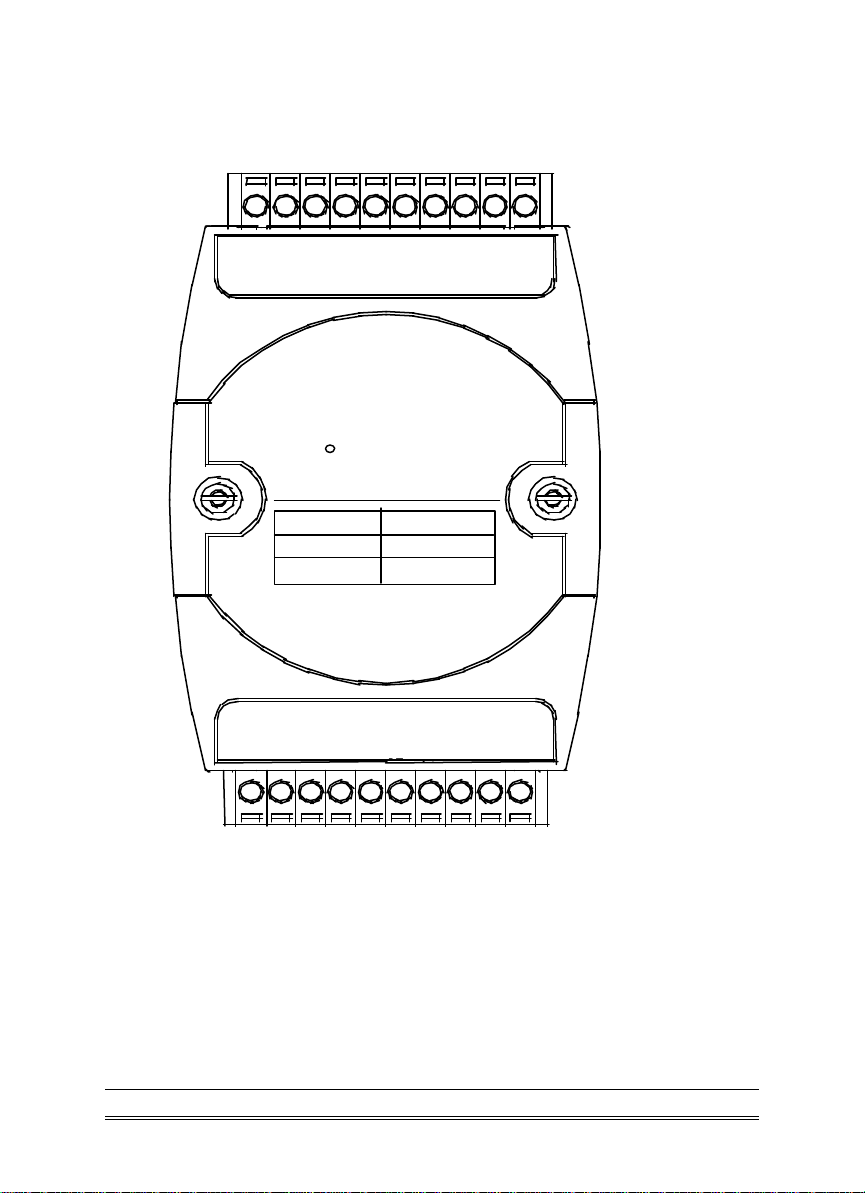
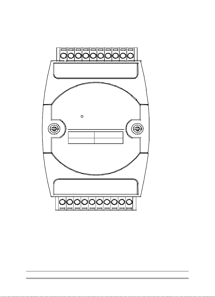
A Look at OMR-6050 & Pin Assignment
D
DI6DI5DI
DI
DI
DOD
O
O
Digital
D
(Y
EF
A
D
O
O
U
(G
)D
)D
A
A
T
T
(B)
10
(R
G
)+
N
DOD
OMR-6050
DOD
O
Introduction 1-3

Pin Definitions of OMR-6050
Pin # Signal Name Description
1 DO 7 Digital output channel 7
2 DO 6 Digital output channel 6
3 DO 5 Digital output channel 5
4 DO 4 Digital output channel 4
5 DO 3 Digital output channel 3
6 Default* Initial state setting
7 (Y) DATA+ RS-485 series signal, positive
8 (G) DATA - RS-485 series signal, negative
9 (R) +Vs Power supply, +10V~+30V
10 (B) GND Ground
11 DO 2 Digital output channel 2
12 DO 1 Digital output channel 1
13 DO 0 Digital output channel 0
14 DI 0 Digital input channel 0
15 DI 1 Digital input channel 1
16 DI 2 Digital input channel 2
17 DI 3 Digital input channel 3
18 DI 4 Digital input channel 4
19 DI 5 Digital input channel 5
20 DI 6 Digital input channel 6
1-4 Introduction
GND
DO7
DI0
DI6
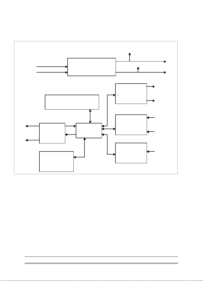
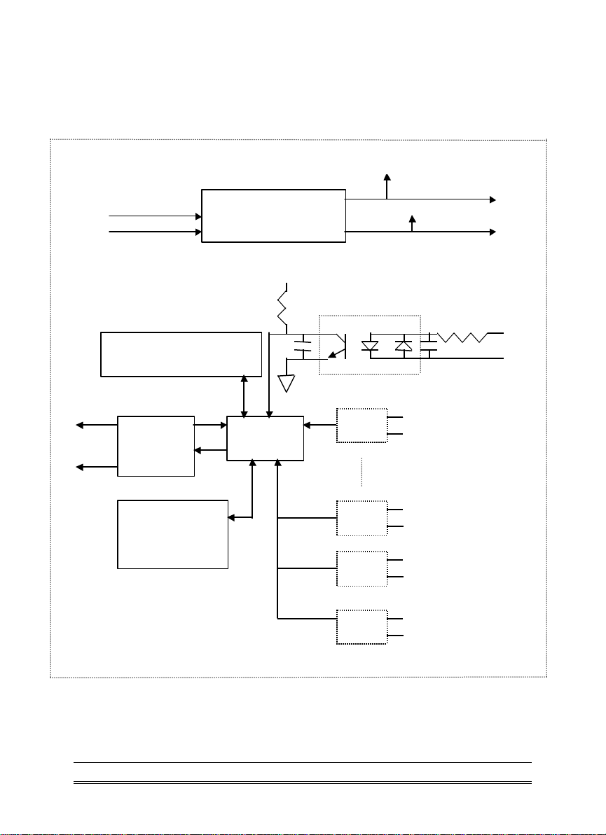
OMR-6050 Functional Block Diagram
Power Input
+10V ~ +30V
Power
Regulator & Filter
Watchdog/Power Failure
Supervisor
Data +
Data -
RS-485
Rec/Drv
Micro
Processor
EEPROM
Config Data
Safe Value
+ 5V
8-bit
Digital/Output
7-bit
Digital/Input
1-bit
Digital/Input
DO0
Default*
Pin
Introduction 1-5

1. 3. Overview of OMR-6052
What is OMR-6052 ?
OMR-6052 provides 8 isolated digital input channels. Six of the input
channels are differential type and two of them are single-ended with
common ground. The isolation voltage is up to 5000 Vrms. It is suitable
to use OMR-6052 in industrial environment with the dangerous of high
voltage electric shock.
Features of OMR-6052
• 8 bits isolated input
• 5000 Vrms isolation voltage
• Programmable host watchdog timer for host failure protection
• Internal watchdog timer for device failure protection
• Easy programming by software
• Easy installation and wiring
Specifications of OMR-6052
² Interface
• Interface : RS-485, 2 wires
• Speed (bps) : 1200, 2400, 4800, 9600, 19.2K, 38.4K, 115.2K
(115.2K only for firmware reversion above A4.00)
² Input
• Channel numbers : 6 differential channels, 2 single ended
• Logical level 0 : +1V Max.
• Logical level 1: +3.5V ~ +24V
² Watchdog Function
• Module internal watchdog timer : 150ms
• Power failure threshold : 4.65 V
• Safe value : 8 output channels
• Host programmable watchdog :100 ms ~ 25.5 sec
² Power
• Power supply : +10V to +30V
• Current consumption : 0.4 W
1-6 Introduction
Digital Input
Input Type
Diffential
Single Ended
6
2
Channels
N
0-
11
20
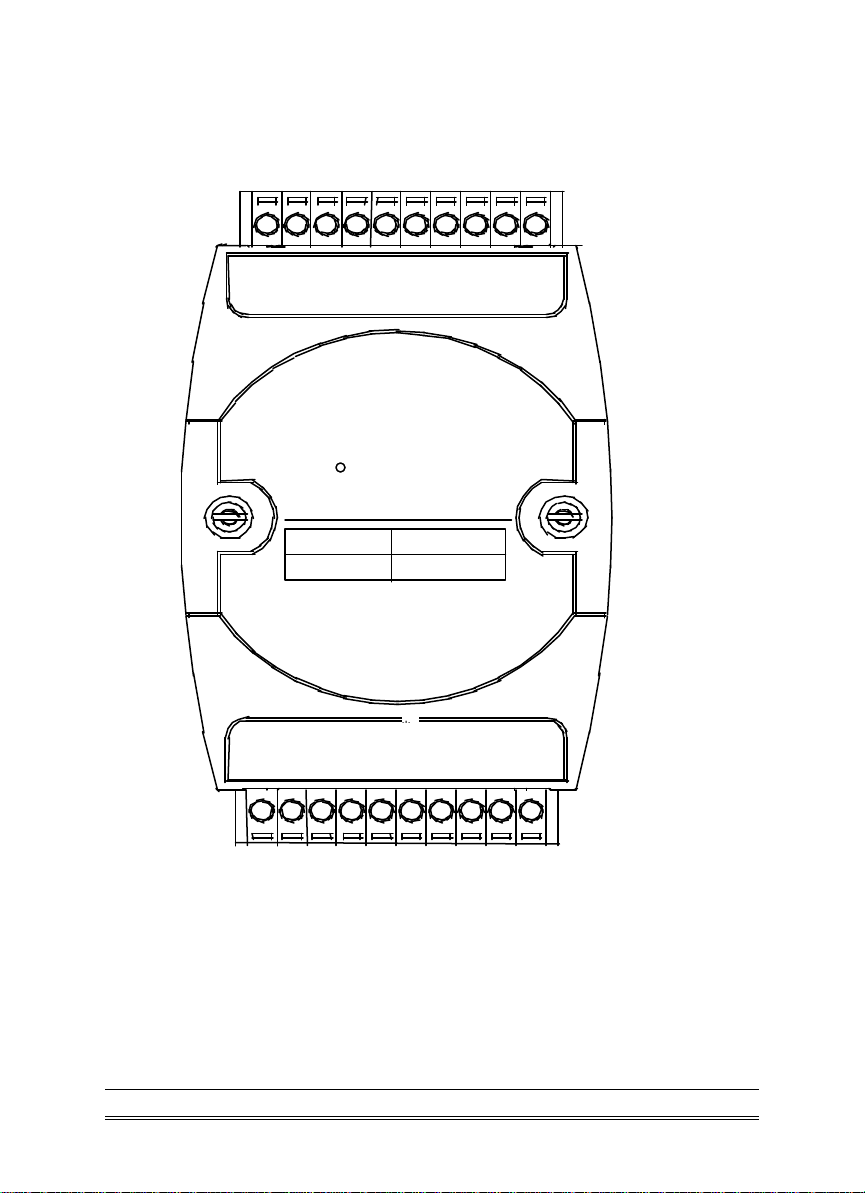
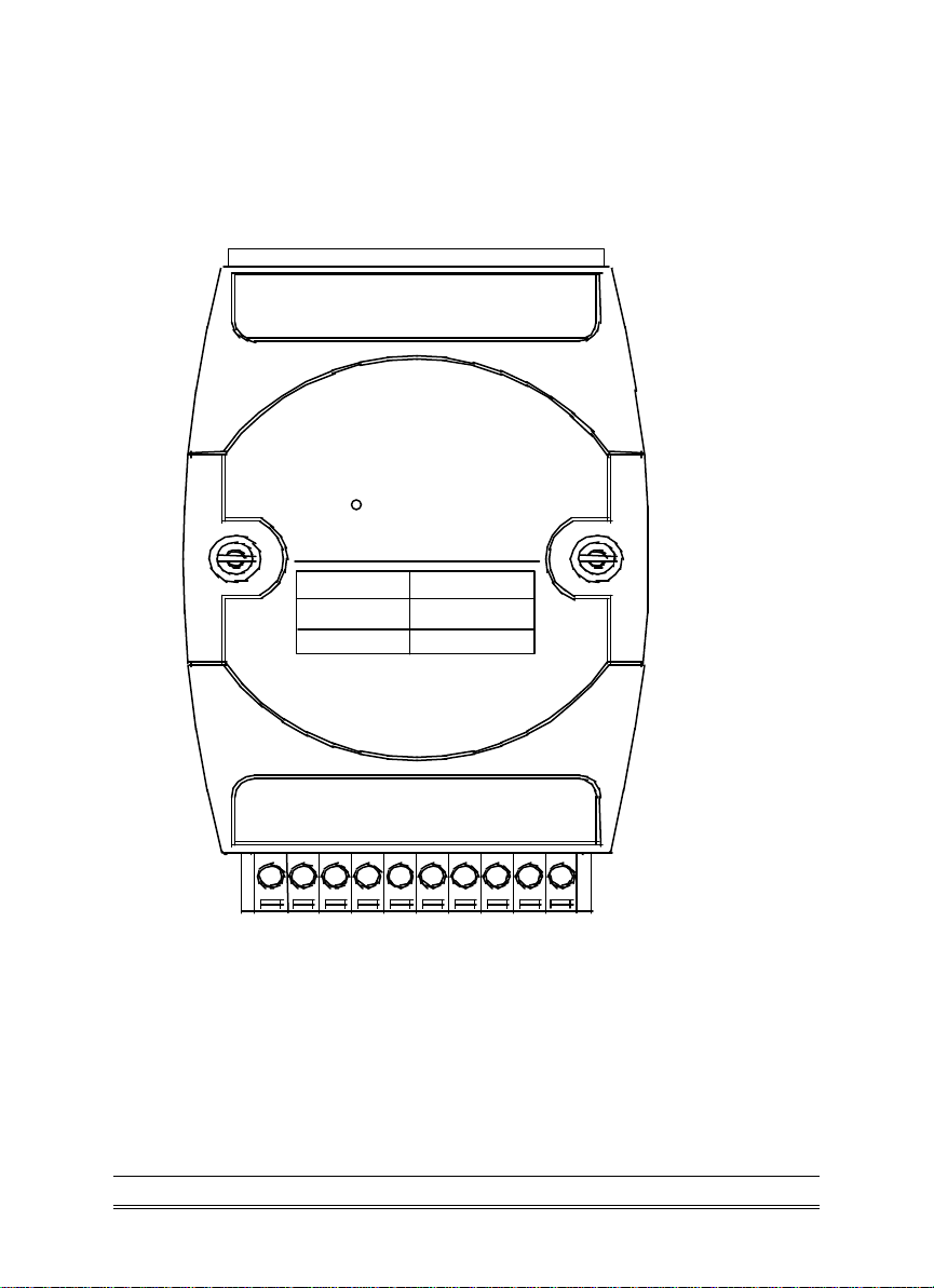
A Look at OMR-6052 & Pin Assignment
DI
DI
DI4+DI
DI
4-
3-
DI
3+
2-
DI
2+
1-DI1+
DI
DI
0+
DI
5+DI5-
OMR-6052
D.
DI
G
6+
DI
7+
Isolated
D
EF
A
U
(Y
(G
)D
)D
A
A
T
T
(B)
10
(R
G
)+
N
Introduction 1-7

Pin Definitions of OMR-6052
Pin # Signal Name Description
1 DI5+ Digital Input Channel 5+
2 DI5 - Digital Input Channel 5 3 DI6+ Digital Input Channel 6+
4 D.GND Digital Input Ground
5 DI7+ Digital Input Channel 7+
6 Default* Initial state setting
7 (Y) DATA+ RS-485 series signal, positive
8 (G) DATA - RS-485 series signal, negative
9 (R) +VS Power supply, +10V~+30V
10 (B) GND Ground
11 DI0+ Digital Input Channel 0+
12 DI0 - Digital Input Channel 0 13 DI1+ Digital Input Channel 1+
14 DI1 - Digital Input Channel 1 15 DI2+ Digital Input Channel 2+
16 DI2 - Digital Input Channel 2 17 DI3+ Digital Input Channel 3+
18 DI3 - Digital Input Channel 3 19 DI4+ Digital Input Channel 4+
20 DI4 - Digital Input Channel 4 -
1-8 Introduction

GND
DI0+
DI6+
DI7+
DI5+
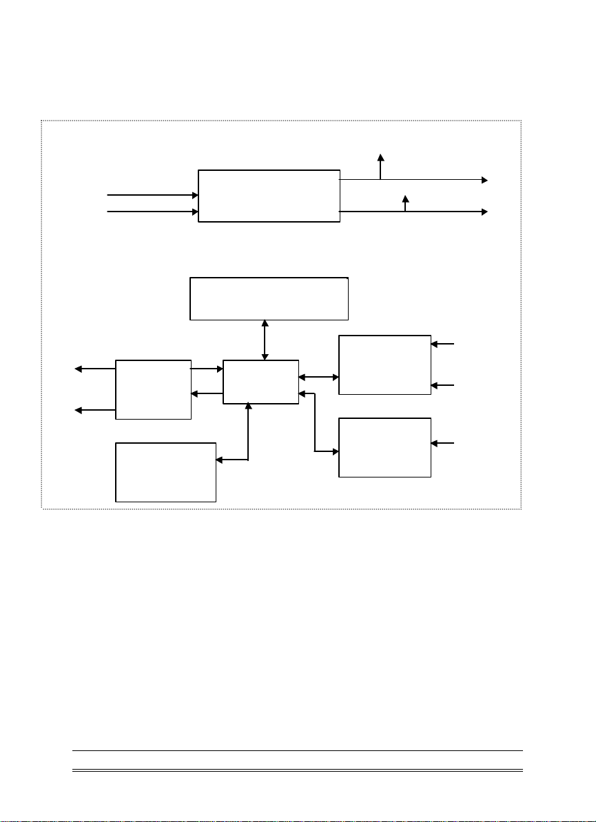
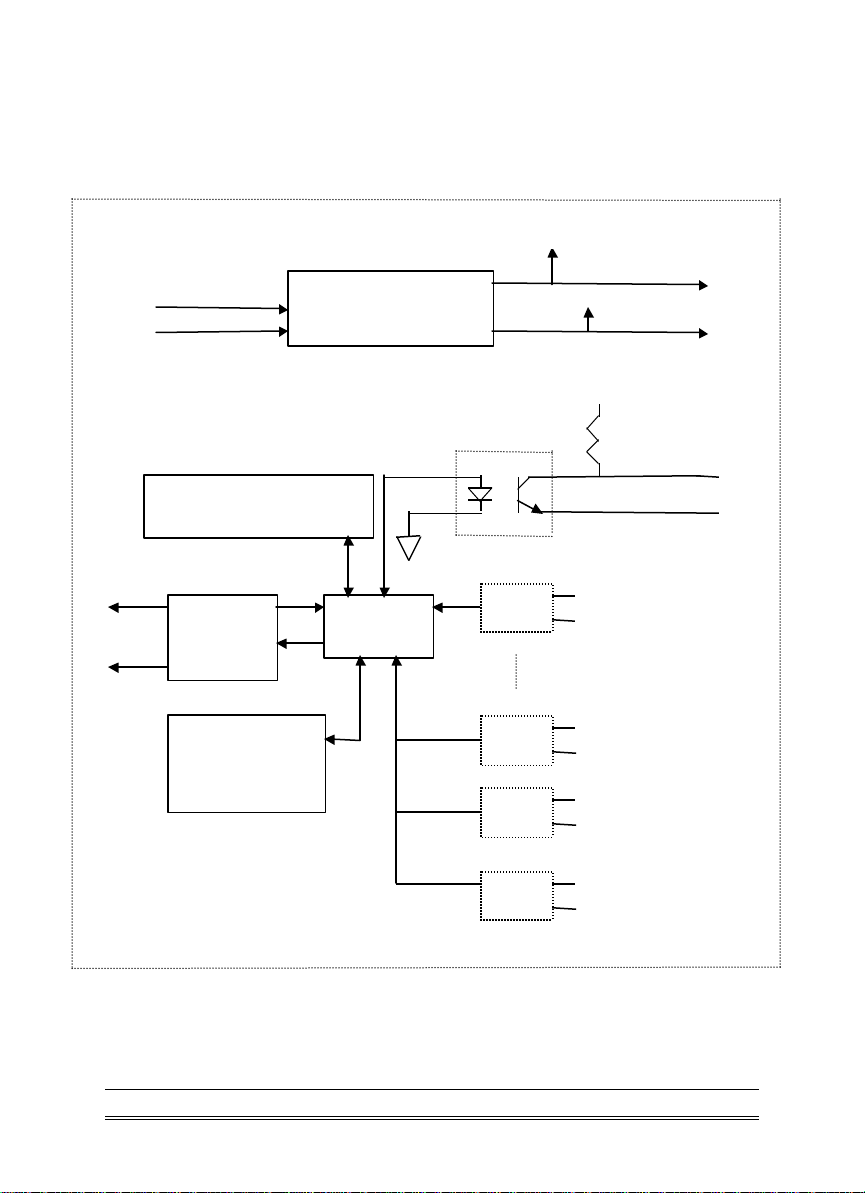
OMR-6052 Functional Block Diagram
Power Input
+10V ~ +30V
Power
Regulator & Filter
+5V
Watchdog/Power Failure
Supervisor
Data -
RS-485
Rec/Drv
Micro
Processor
EEPROM
Config Data
Safe Value
+5V
DI0+
DI0-
DI0-
DI5-
D.GND
D.GND
Introduction 1-9

1. 4. Overview of OMR-6053
What is OMR-6053 ?
OMR-6053 provides 16 digital input channels for dry contact or wet
contact signals. The effective distance from DI to contact point is up to
500m for dry contact input.
Features of OMR-6053
• 16 bits digital input
• Programmable host watchdog timer for host failure protection
• Internal watchdog timer for device failure protection
• Easy programming by software
• Easy installation and wiring
Specifications of OMR-6053
² Interface
• Interface : RS-485, 2 wires
• Speed (bps) : 1200, 2400, 4800, 9600, 19.2K, 38.4K, 115.2K
(115.2K only for firmware reversion above A4.00)
² Input
• Channel numbers : 16
• Dry Contact:
Logical level 0: close to GND
Logical level 1: open
• Wet Contact:
Logical level 0: +2V max.
Logical level 1: +4V ~ + 30V
² Watchdog Function
• Module internal watchdog timer : 150ms
• Power failure threshold : 4.65 V
• Host programmable watchdog :100 ms ~ 25.5 sec
² Power
• Power supply : +10V to +30V
• Current consumption : 0.4 W
1-10 Introduction
OMR-6053
Input Type
Digital Input
16
Channels
/DI 15
A Look at OMR-6053 & Pin Assignment
DI 9
DI 7
DI 6
DI 5
DI 4
DI 3
DI 2
DI 1
DI 8
20
16-CH
Digital Input
DI 0
11
1
(Y)DATA+
DI 10
DI 11
DI 12
DI 13
DI 14
DEFAULT
(G)DATA-
(R)+Vs
10
(B)GND
Introduction 1-11

Pin Definitions of OMR-6053
Pin # Signal Name Description
1 DI10 Digital Input Channel 10
2 DI11 Digital Input Channel 11
3 DI12 Digital Input Channel 12
4 DI13 Digital Input Channel 13
5 DI14 Digital Input Channel 14
6 Default*
/DI15
Initial state setting
/ Digital Input Channel 15
7 (Y) DATA+ RS-485 series signal, positive
8 (G) DATA - RS-485 series signal, negative
9 (R) +VS Power supply, +10V~+30V
10 (B) GND Ground
11 DI0 Digital Input Channel 0
12 DI1 Digital Input Channel 1
13 DI2 Digital Input Channel 2
14 DI3 Digital Input Channel 3
15 DI4 Digital Input Channel 4
16 DI5 Digital Input Channel 5
17 DI6 Digital Input Channel 6
18 DI7 Digital Input Channel 7
19 DI8 Digital Input Channel 8
20 DI9 Digital Input Channel 9
1-12 Introduction
GND
+10V ~ +30V
DI0
DI14
OMR-6053 Functional Block Diagram
Power Input
Data +
Data -
RS-485
Rec/Drv
EEPROM
Config Data
Safe Value
Power
Regulator & Filter
Watchdog/Power Failure
Supervisor
Micro
Processor
+ 5V
15-bit
Digital/Input
1-bit
Digital/Input
Default*
Pin/DI15
Introduction 1-13

1. 5. Overview of OMR-6054
What is OMR-6054 ?
OMR-6054 provides 15 isolated digital input channels. All of the input
channels are common power type and one of them is using the same
pin with default (use jumper to choose). The isolation voltage is up to
5000 Vrms. It is suitable to use OMR-6054 in industrial environment with
the dangerous of high voltage electric shock.
Features of OMR-6054
• 15 bits digital inputs with isolation protection and common power
• 5000 Vrms isolation voltage
• Programmable host watchdog timer for host failure protection
• Internal watchdog timer for device failure protection
• Easy programming by software
• Easy installation and wiring
Specifications of OMR-6054
² Interface
• Interface : RS-485, 2 wires
• Speed (bps) : 1200, 2400, 4800, 9600, 19.2K, 38.4K, 115.2K
(115.2K only for firmware reversion above A4.00)
² Input
• Channel numbers : 15 isolation common power input channels
(the fifteenth channel is the same with default pin, but can use
jumper to choose).
• Input type : source type .
Effective distance: 500 m.
• Common external voltage: 24V.
² Watchdog Function
• Module internal watchdog timer : 150msec
• Power failure threshold : 4.65 V
• Host programmable watchdog :100 ms ~ 25.5 sec
² Power
• Power supply : +10V to +30V
• Power consumption : 0.4 W
1-14 Introduction

Input Type
DI
15
Channels
/DI14
DI0
DI1
DI2
DI3
DI4
DI5
DI6
DI7
DI8
DI9
11
20
A Look at OMR-6054 & Pin Assignment
DI10
OMR-6054
DI11
DI12
DI13
15-CH Isolated
Digital Input
Ext24V
DEFAULT
(G)DATA-
(Y)DATA+
(R)+Vs
10
(B)GND
Introduction 1-15

Initial state setting or digital input
Pin Definitions of OMR-6054
Pin # Signal Name Description
1 DI10 Digital input channel 10
2 DI11 Digital input channel 11
3 DI12 Digital input channel 12
4 DI13 Digital input channel 13
5 Ext24V External common +24V
6 Default*/DI14
7 (Y) DATA+ RS-485 series signal, positive
8 (G) DATA - RS-485 series signal, negative
9 (R) +VS Power supply, +10V~+30V
10 (B) GND Ground
11 DI9 Digital input channel 9
12 DI8 Digital input channel 8
13 DI7 Digital input channel 7
14 DI6 Digital input channel 6
15 DI5 Digital input channel 5
16 DI4 Digital input channel 4
17 DI3 Digital input channel 3
18 DI2 Digital input channel 2
19 DI1 Digital input channel 1
20 DI0 Digital input channel 0
channel 14
1-16 Introduction
GND
+24V
Data +
OMR-6054 Functional Block Diagram
Power Input
+10V ~ +30V
Watchdog/Power Failure
Supervisor
RS-485
Rec/Drv
Data -
EEPROM
Config Data
Safe Value
Power
Regulator & Filter
+5V
Micro
Processor
+5V
+24V
DI0
DI1
+24V
DI12
+24V
DI13
+24V
DI14
Introduction 1-17

1. 6. Overview of OMR-6056
What is OMR-6056 ?
OMR-6056 provides 15 isolated digital output channels. All of the output
channels are common ground type and one of them is use the same pin
with default (use jumper to choose). The isolation voltage is up to 5000
Vrms. It is suitable to use OMR-6056 in industrial environment with the
dangerous of high voltage electric shock.
Features of OMR-6056
• 15 bits digital open collector output with isolation protection and
common ground
• 5000 Vrms isolation voltage
• Programmable host watchdog timer for host failure protection
• Internal watchdog timer for device failure protection
• Easy programming by software
• Easy installation and wiring
Specifications of OMR-6056
² Interface
• Interface : RS-485, 2 wires
• Speed (bps) : 1200, 2400, 4800, 9600, 19.2K, 38.4K, 115.2K
(115.2K only for firmware reversion above A4.00)
² Digital Output
• Channel numbers : 15 isolation common ground output
channels(the fifteenth channel is the same with default pin,but
could use jumper to choose).
• Output characteristic:open collector transistor.
• Maximum current sink:50mA
Max.power dissiation:200mW
Isolation Voltage:5000Vrms
² Watchdog Function
• Module internal watchdog timer : 150msec
• Power failure threshold : 4.65 V
• Safe value : 15 output channels
• Host programmable watchdog :100 ms ~ 25.5 sec
² Power
• Power supply : +10V to +30V
1-18 Introduction

• Current consumption : 0.3 W
Introduction 1-19
Output Type
DO
15
Channels
/DO14
DO9
DO8
DO7
DO6
DO5
DO4
DO3
DO2
DO1
DO0
11
20
A Look at OMR-6056 & Pin Assignment
DO10
OMR-6056
DO11
DO12
DO13
15-CH Isolated
Digital Output
Ext.GND
DEFAULT
(G)DATA-
(Y)DATA+
(R)+Vs
10
(B)GND
1-20 Introduction

Pin Definitions of OMR-6056
Pin # Signal Name Description
1 DO10 Digital output channel 10
2 DO11 Digital output channel 11
3 DO12 Digital output channel 12
4 DO13 Digital output channel 13
5 ExtGND
6 Default*/
DO14
Initial state setting
Digital output channel 14
7 (Y) DATA+ RS-485 series signal, positive
8 (G) DATA - RS-485 series signal, negative
9 (R) +VS Power supply, +10V~+30V
10 (B) GND Ground
11 DO0 Digital output channel 0
12 DO1 Digital output channel 1
13 DO2 Digital output channel 2
14 DO3 Digital output channel 3
15 DO4 Digital output channel 4
16 DO5 Digital output channel 5
17 DO6 Digital output channel 6
18 DO7 Digital output channel 7
19 DO8 Digital output channel 8
20 DO9 Digital output channel 9
Introduction 1-21
GND
DO1
DO13
DO14
Data +
OMR-6056 Functional Block Diagram
Power Input
+10V ~ +30V
Watchdog/Power Failure
Supervisor
RS-485
Rec/Drv
Data -
EEPROM
Config Data
Safe Value
Power
Regulator & Filter
Micro
Processor
+5V
+V
DO0
COM
COM
DO12
COM
COM
COM
1-22 Introduction

1. 7. Overview of OMR-6058
What is OMR-6058 ?
OMR-6058 provides 28 digital I/O channels. It emulates industry
standard mode zero configuration of 8255 programmable peripheral
interface (PPI) chip. The PPI offers 3 ports A, B and C, the C port
can also be subdivided into 2 nibble-wide (4-bit) port – C upper and C
lower. A 50 pin SCSI connector equipped with OMR-6058 which is
corresponding to PPI chip with 24 DIO points.
Features of OMR-6058
• Industry standard 8255 programmable peripheral interface mode
0 emulation
• 24 Programmable I/O channels
• 4 dedicated input channels
• Completely TTL compatible I/O lines
• Status read-back capability
• Direct bit set/reset capability
• Buffered circuits for higher driving capability
• Direct interface with OPTO-22 compatible I/O module
• Programmable host watchdog timer for host failure protection
• Internal watchdog timer for device failure protection
• On board resetable fuse to protect power supply form external
devices
• Easy programming by software
• Easy installation and wiring
Specifications of OMR-6058
² Interface
• Interface : RS-485, 2 wires
• Speed (bps) : 1200, 2400, 4800, 9600, 19.2K, 38.4K, 115.2K
(115.2K only for firmware reversion above A4.00)
² Programmable Digital Input/Output
• Channel numbers : 24
• Input Signal:
Introduction 1-23

Logical level 0 : -0.5 ~ 0.8 V
Logical level 1: 2.0 ~ 5.25 V
• Output Signal:
Logical level 0: 0.5 V Maximum
Logical level 1: 2.4 V Minimum Digital Output
²
² Watchdog Function
• Module internal watchdog timer : 150msec
• Power failure threshold : 4.65 V
• Safe value : 15 output channels
• Host programmable watchdog :100 ms ~ 25.5 sec
²
² Dedicated Digital Input
• Channel numbers : 4
• Input Signal:
Logical level 0: 2 V max.
Logical lev el 1: 3 V ~ 5.25 V
²
² Connector
• 10-pin skew terminal block
• 50-pin SCSI II connector
²
² Power
• Power supply : +10V to +30V
• Current consumption: 1.7 W
1-24 Introduction
Type
PPI
24
Channels
A0~A7
B0~B7
C0
C7
50
1
A Look at OMR-6058 & Pin Assignment
~
DI0
OMR-6058
DI
DI1
DI2
28-CH Programmable
Digital I/O
DI3
DEFAULT
(G)DATA-
(Y)DATA+
(R)+Vs
10
(B)GND
Introduction 1-25
 Loading...