

Page 1

M-3580 for
OMR-6011/D OMR-6014D
OMR-6012/D OMR-6017
OMR-6013 OMR-6018
Analog Input Modules
Page 2

Contents
1 Introduction ................................................. 1-1
1. 1. ABOUT THE OMR ANALOG INPUT MODULES....................................1-1
1. 2. OVERVIEW OF OMR-6011/D.....................................................................1-1
1. 3. OVERVIEW OF OMR-6012/D.....................................................................1-6
1. 4. OVERVIEW OF OMR-6013 ...................................................................... 1-10
1. 5. OVERVIEW OF OMR-6014D ................................................................... 1-13
1. 6. OVERVIEW OF OMR-6017 ...................................................................... 1-17
1. 7. OVERVIEW OF OMR-6018 ...................................................................... 1-20
2. Initialization & Installation........................2-1
2. 1. SOFTWARE INSTA LLATION.....................................................................2-1
2. 2. INITIALIZING A BRAND NEW MODULE.................................................2-1
2. 3. INSTALL A NEW OMR TO A EXISTING NETWORK ............................2-4
2. 4. APPLICATION WI RING FOR OMR-6011/D/6012/D/6013/6014D/6017/6018 2-5
3. Command Set..............................................3-1
3. 1. COMMAND AND RESPONSE....................................................................3-1
3. 2. SUMMARY OF COMMAND SET ...............................................................3-3
3. 3. SET CONFIGURAT ION...............................................................................3-6
3. 4. READ CONFIGURATION.........................................................................3-10
3. 5. READ MODULE NA ME............................................................................3-11
3. 6. READ FIRMWARE VERSION.................................................................3-12
3. 7. SYNCHRONIZED SAMPLING.................................................................3-13
3. 8. READ SYNCHRONIZED DATA..............................................................3-14
3. 9. READ ANALOG DATA ............................................................................. 3-16
3. 10. SPAN CALIBRATION ...............................................................................3-17
3. 11. SPAN CALIBRATION TO EACH CHANNEL .......................................3-18
3. 12. OFFSET CALIBRATION...........................................................................3-19
3. 13. OFFSET CALIBRATION TO EACH CHANNEL...................................3-20
3. 14. READ ANALOG D ATA FROM CHANNEL N....................................... 3-21
3. 15. READ ALL ANAL OG DATA CHANNEL ...............................................3-22
3. 16. ENABLE/DISABLE CHANNELS FOR MULTIPLEXING .................... 3-23
3. 17 READ CHANNEL S TATUS ......................................................................3-24
3. 18. READ CJC STAT US .................................................................................3-25
3. 19. READ OPEN THERMOCOUPLE DETECTION OF CHANNEL N....3-26
3. 20. ENABLE/DISABLE OPEN THERMOCOUPLE DETECTION............3-28
3. 21. READ SOURCE HIGH/LOW VALUES FOR LINEAR MAPPING ..... 3-29
3. 22. READ TARGET HIGH/LOW VALUES FOR LINEAR MAPPING......3-30
3. 23. WRITE SOURCE HIGH/LOW VALUES FOR LINEAR MAPPING ....3-31
3. 24. WRITE TARGET HIGH/LOW VALUES FOR LINEAR MAPPING.... 3-33
3. 25. ENABLE/DISABLE LINEAR MAPPING................................................3-34
3. 26. READ ENABLE/DISABLE LINEAR MAPPING STATUS...................3-35
3. 27. CJC OFFSET CALIBRATION.................................................................3-36
3. 28. CLEAR LATCHED ALARM .....................................................................3-37
3. 29. CLEAR EVENT COUNTER......................................................................3-38
3. 30. DISABLE ALARM ......................................................................................3-39
3. 31. READ DIGITAL I/O AN D ALARM STATUS..........................................3-40
3. 32. SET DIGITAL OUTPUT.............................................................................3-42
3. 33. ENABLE ALARM .......................................................................................3-43
3. 34. SET HIGH ALARM.....................................................................................3-44
Contents i
Page 3

3. 35. SET LOW ALARM .....................................................................................3-45
3. 36. READ EVENT COUNTER........................................................................3-46
3. 37. READ HIGH ALA RM LIMIT ..................................................................... 3-47
3. 38. READ LOW ALARM LIMIT ......................................................................3-48
3. 39. READ LEADING CODE SETTING.........................................................3-49
3. 40. CHANGE LEADING CODE SETTING...................................................3-51
3. 41. SET HOST WATCHDOG TIMER & SAFETY VALUE.........................3-53
3. 42. READ HOST WAT CHDOG TIMER & SAFETY VALUE..................... 3-55
3. 43. HOST IS OK................................................................................................3-56
4. Data Format and Input Range...................4-1
4. 1. DATA FORMAT OF ANALOG INPUT MODULES .................................4-1
4. 2. ANALOG INPUT R ANGE............................................................................4-6
5. Calibration ...................................................5-1
5. 1. HOW TO CALIBRA TE THE ANALOG INPUT MODULES ?................5-1
ii Content
Page 4

1. Introduction
1. 1. About the OMR Analog Input Modules
The OMR provides a series of analog input modules which can sense the ana log signal or to control the remote devices.
The basic features of each module are shown here.
• OMR-6011/D : multi-functions high gain analog input module
• OMR-6012/D : multi-functions analog input module
• OMR-6013 : 3 channels RTD input module
• OMR-6014D:Analog (Transmitter) input module with LED display
• OMR-6017 : 8 channels analog input module
• OMR-6018 : 8 channels thermocouple input module
V The models with an extended D have the same command set and specification as without D, except the D version has a 5
1/2 LED Display.
1. 2. Overview of OMR-6011/D
What is OMR-6011/D ?
OMR-6011/D is a multi-functions analog input module with cold junction compensation (CJC). The maximum input voltage
range of analog input channel is ±2.5V. The high gain feature allows very small full range of ±15mV. To measure
temperature by directly connect the thermal couple is possible because of using the CJC inside and the high gain feature.
The voltage range of the ADC can be set according to different types of thermal couple. The ADC can be calibrated by
programming without handy adjustment. This feature insure the best performance under different environment.
The module provides the analog signal monitor or the alarm function. The high and low bound of the alarm limit can be se t
by programming. The alarm status can be sent to digital output channels if this function is ON. The supervisor of a factory
can ‘see’ or ‘hear’ the alarm if the digital output channel control a real alarm device. The two digital output channels can be
set for general purpose use if the alarm is disabled.
Introduction 1-1
Page 5

For example, connecting relay devices to DO channels, the OMR-6011/D can be used to control the high power devices.
The module provides another one digital input channel. This can be used for general purpose such as monitor digital
signal, or be used as input of the event counter.
Features of OMR-6011/D
• 1 analog input channel with differential input
• programmable voltage range with high gain amplifier
• Self offset and gain calibration
• On board CJC for temperature measurement
• 5000 Vrms isolation voltage for AD channel (2500 Vrms for OMR-6011/D)
• 2 digital output channels of open collector type
• Alarm function with high / low alarm output
• 1 digital input channel / event counter
• Programmable host watchdog timer for host failure protection
• Internal watchdog timer for device failure protection
• Easy programming by software
• Easy installation and wiring
• 5 1/2 digital LED Display (OMR-6011/D)
Specifications of OMR-6011/D
² Interface
• Interface : RS-485, 2 wires
• Speed (bps) : 1200, 2400, 4800, 9600, 19.2K, 38.4K,115.2K (115.2K only for firmware reversion above A4.00)
² Analog Input
• Input type: Differential input
• Resolution: 16 bits
• Unit Convertion: Thermocouple, mV, V, or mA
• Thermocouple Type: J, K, T, E, R, S, B, N, C
J: 0°C~760°C K: 0°C~1000°C
T: -100°C~400°C E: 0°C~1000°C
R: 500°C~1750°C S: 500°C~1750°C
B: 500°C~1800°C N: -270°C~1300°C
C: 0°C~2320°C
• Voltage Range: Programmable 6 levels
±2.5V, ±1V, ±500mV, ±100mV, ±50mV, ±15mV
• Current Measurement: 20mA (with external 125Ω resistor)
• Accuracy: ±0.4%
² Digital Output
• Channel numbers : 2
• Output characteristic : open collector transistor
• Maximum current sink : 50mA
• Max. power dissipation : 300mW
² Digital Input
• Channel numbers : 1
• Logical level 0 : +1V maximum
• Logical level 1: +2.0V~ +30V
• Pull up resister : 10KΩ
• Maximum current : 0.5mA
² Watchdog Function
• Module internal watchdog timer : 150 ms
• Power failure threshold : 4.65 V
• Safety value : 2 digital output channels
• Host programmable watchdog : 100 ms ~ 25.500 sec
² Power
1-2 Introduction
Page 6

• Power supply : +10V to +30V
• Current consumption : 0.76W(1.68W for OMR-6011/D)
Introduction 1-3
Page 7
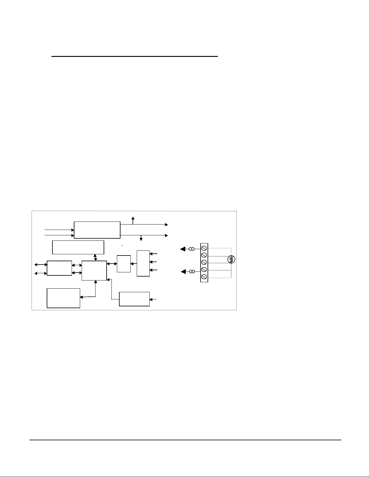
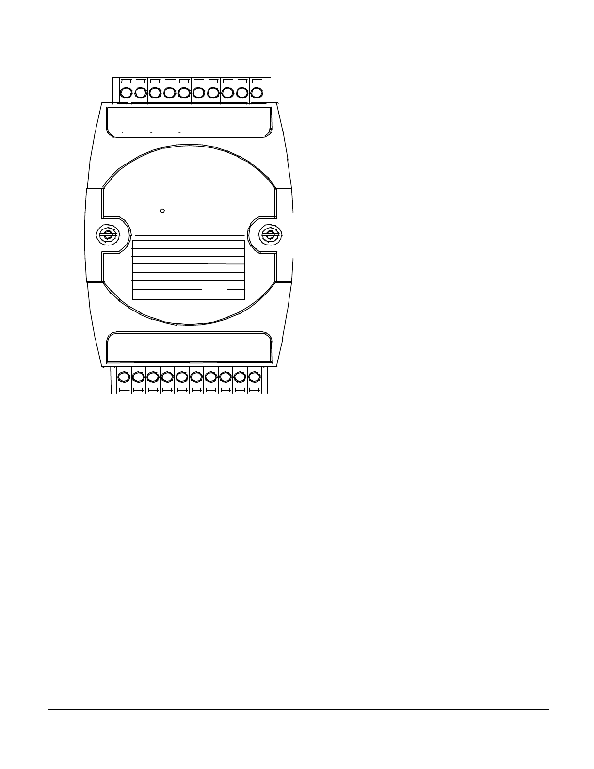
Pin Definitions of OMR-6011/D
Power Input
Power
Regulator & Filter
RS-485
EEPROM
Safe Value
Watchdog/Power Failure
1-bit
Digital Input
1-bit
Digital Input
2-bits
Digital Output
Analog
Signal
DO0
DO1
Default*
LED Display
Pin # Signal Name Description
1
IN+ Analog Input Positive Terminal
2 IN- Analog Input Negative Terminal
3 DO 1/ HI Digital Output Channel 1
or High alarm status output
4 DI 0 / EV Digital Input Channel 0
or event counter input
5 DO 0 / LO Digital Output Channel 0
or Low alarm output
6 DEFAULT* Initial state setting
7 (Y) DATA+ RS-485 series signal, positive
8 (G) DATA - RS-485 series signal, negative
9 (R) +Vs Power supply, +10V~+30V
10 (B) GND Ground
11 TC(+) Thermocouple Input positive Terminal
12 TC(-) Thermocouple Input negative Terminal
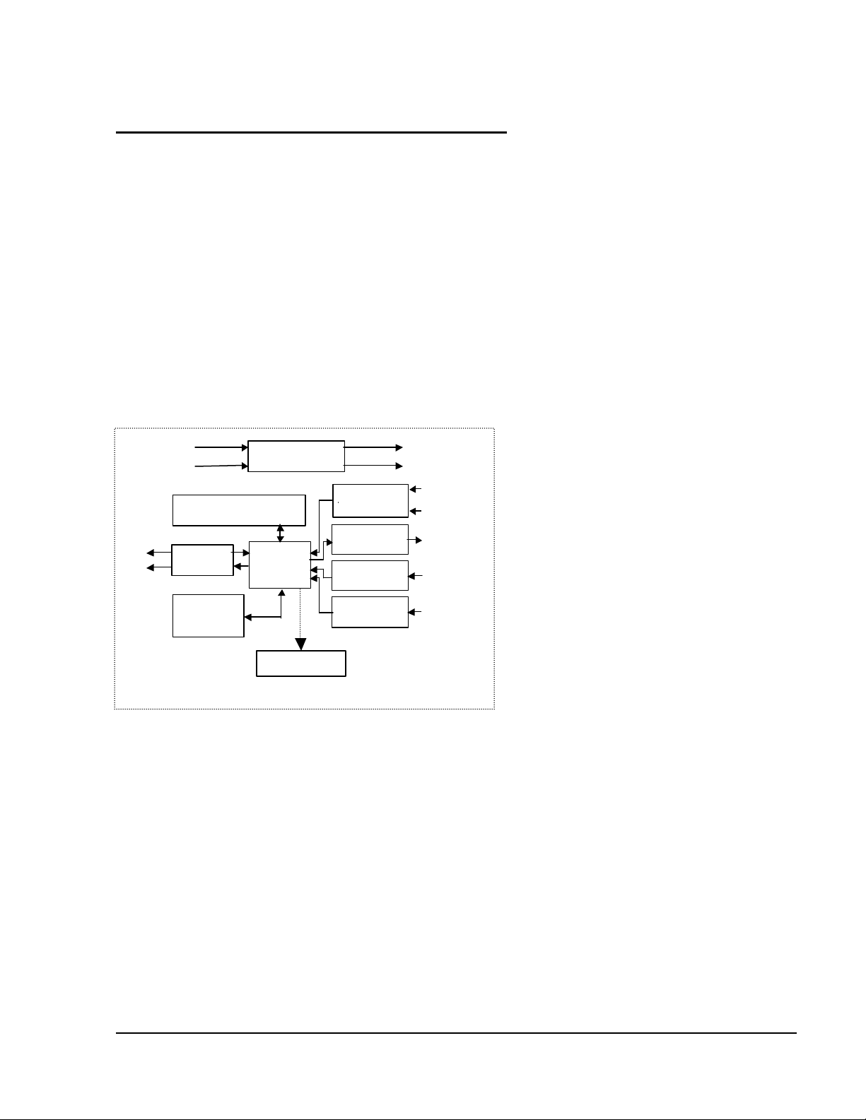
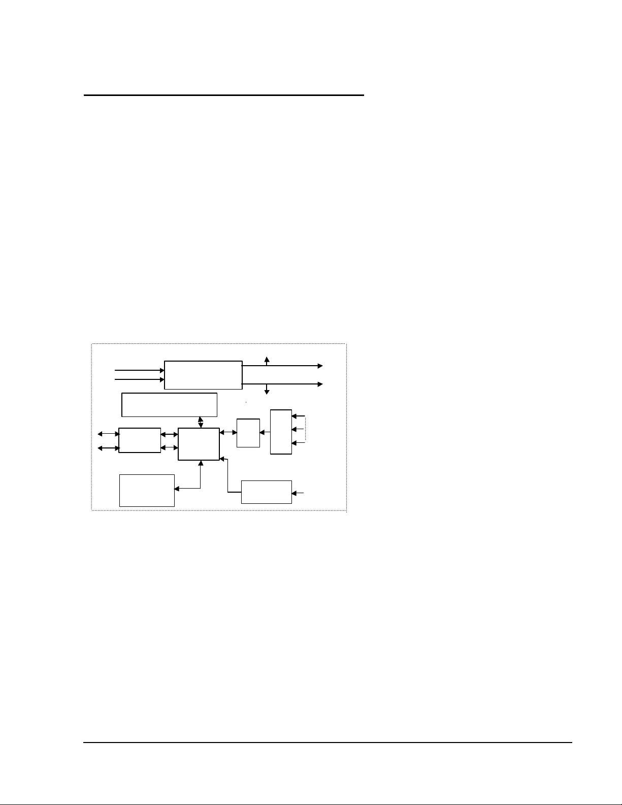
Functional Block Diagram of OMR-6011/D
+ 5V
+10V ~ +30V
Supervisor
GND
ADC
CJC
Data +
Data -
Rec/Drv
Config Data
Micro
Processor
(only OMR-6011/D)
Pin
1-4 Introduction
Page 8
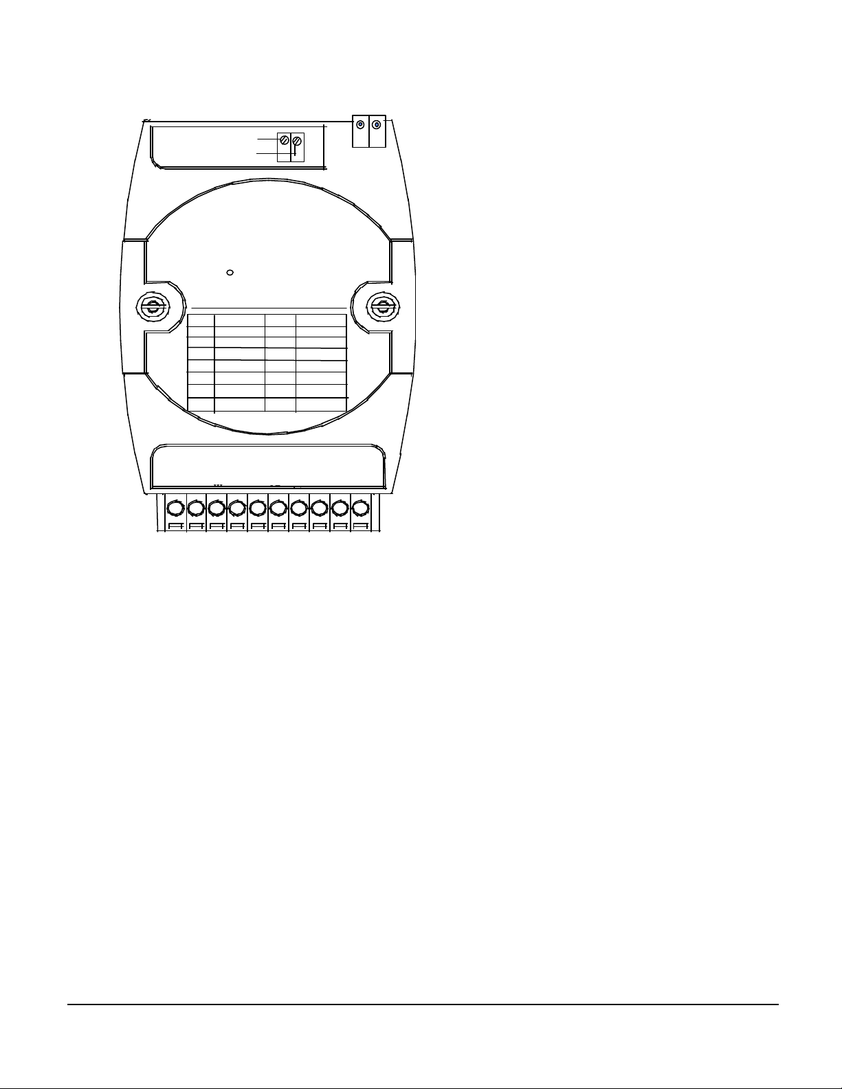
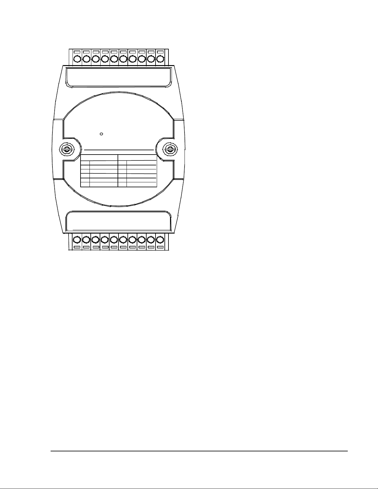
A Look at OMR-6011/D & Pin Assignment
Input
E
T/C (-)
T/C (+)
OMR-6011
Code mV/mA Code
15 mV
00
01
50 mV
02
100 mV
03
500 mV
04
1 V
2.5 V
05
20 mA
06
5 V
IN
(+)
D
IN
O
1/
(-)
D
DI
O
0/
0/
High Gain Analog
T/C
J Type
0E
0F
K Type
10
T Type
11
E Type
12
R Type
13
S Type
14
B Type
D
(Y
EF
A
U
(G
)D
)D
A
A
T
T
(B)
10
(R
G
)+
N
Introduction 1-5
Page 9

1. 3. Overview of OMR-6012/D
What is OMR-6012/D?
OMR-6012/D is a multi-functions analog input module. The programmable input voltage range of analog input channel is
from ±10V maximum to ±150mV minimum.
The module also provides the alarm function and the event counter just like OMR -6011/D. In fact, the OMR -6012/D
provides almost all functions that OMR-6011/D has except the CJC and temperature measurement function.
Features of OMR-6012/D
• 1 analog input channel with differential input
• Programmable voltage range
• Self gain and offset calibration
• 5000 Vrms isolation voltage for AD channel (2500 Vrms for OMR-6012/D)
• 2 digital output channels of open collector type
• Alarm function with high / low alarm output
• 1 digital input channel / event counter
• Programmable host watchdog timer for host failure protection
• Internal watchdog timer for device failure protection
• Easy programming by software
• Easy installation and wiring
• 51/2 digital LED display (OMR-6012/D)
Specifications of OMR-6012/D
² Interface
• Interface : RS-485, 2 wires
• Speed (bps) : 1200, 2400, 4800, 9600, 19.2K, 38.4K ,115.2K (115.2K only for firmware reversion above A4.00)
² Analog Input
• Input type: Differential input
• Resolution: 16 bits
• Unit Convertion: mV, V, or mA
• Voltage Range: Programmable 5 levels
±10V, ±5V, ±1V, ±500mV, ±150mV
• Current Measurement: 20mA (with external 125Ω resistor)
• Accuracy: ±0.05%
• Isolation Voltage : 5000 Vrms(2500 Vrms for OMR-6012/D)
² Digital Output
• Channel numbers : 2
• Output characteristic : open collector transistor
• Maximum current sink : 50mA
• Max. power dissipation : 300mW
² Digital Input
• Channel numbers : 1
• Logical level 0 : +1V maximum
• Logical level 1: +2.0V~30V
• Pull up resister : 10KΩ
• Maximum current : 0.5mA
² Watchdog Function
• Module internal watchdog timer : 150 ms
• Power failure threshold : 4.65 V
• Host programmable watchdog : 100 ms ~ 25.500 sec
² Power
• Power supply : +10V to +30V
• Current consumption : 1.1 W(2.0W for OMR-6012/D)
1-6 Introduction
Page 10

Introduction 1-7
Page 11
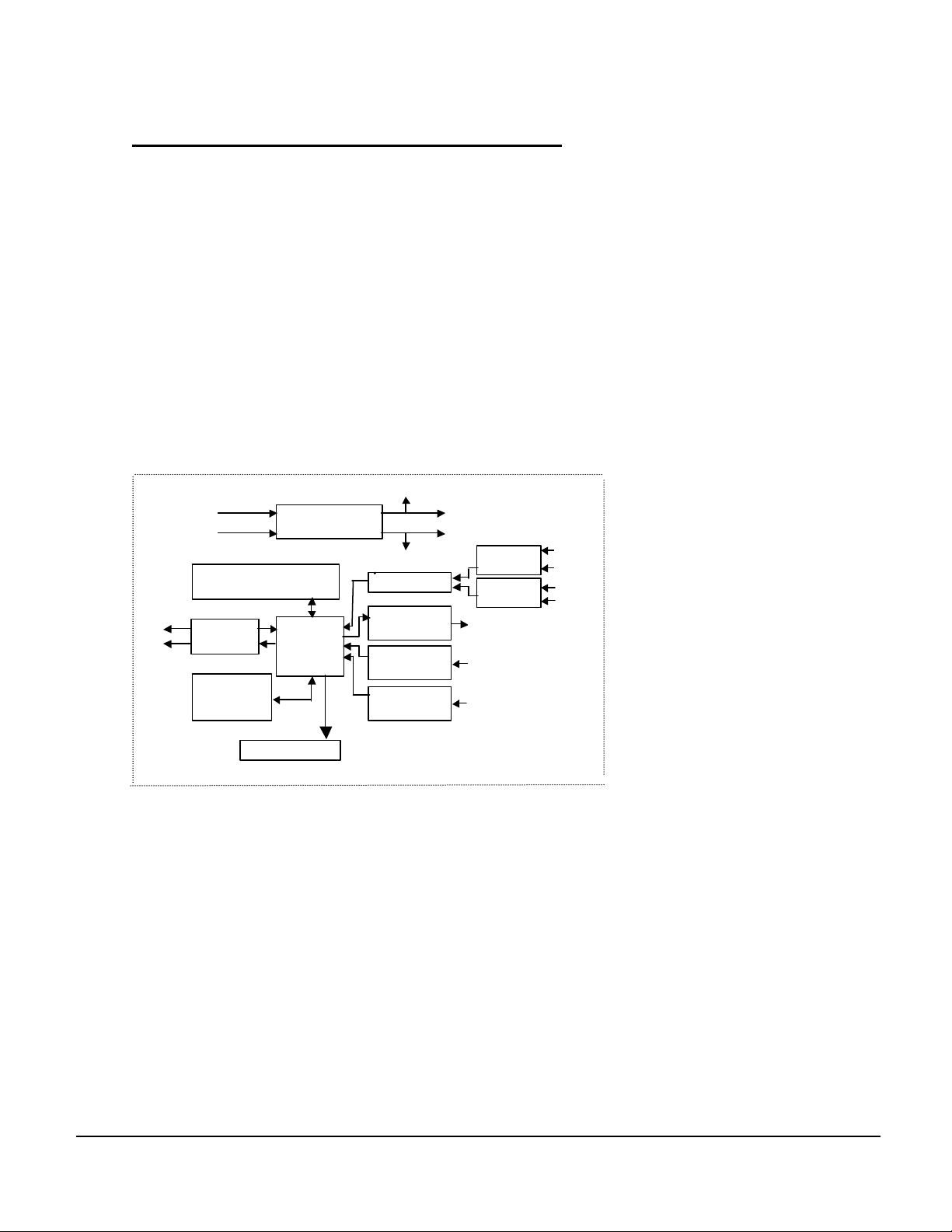
Pin Definitions of OMR-6012/D
Power Input
Power
RS-485
EEPROM
Safe Value
Watchdog/Power Failure
1-bit
Digital Input
1-bit
Digital Input
2-bits
Digital Output
Analog
Signal
DO0
DO1
Default*
Pin # Signal Name Description
1 IN+ Analog Input Positive Terminal
2 IN- Analog Input Negative Terminal
3 DO 1/ HI Digital Output Channel 1
or High alarm status output
4 DI 0 / EV Digital Input Channel 0
or event counter input
5 DO 0 / LO Digital Output Channel 0
or Low alarm output
6 DEFAULT* Initial state setting
7 (Y) DATA+ RS-485 series signal, positive
8 (G) DATA - RS-485 series signal, negative
9 (R) +Vs Power supply, +10V~+30V
10 (B) GND Ground
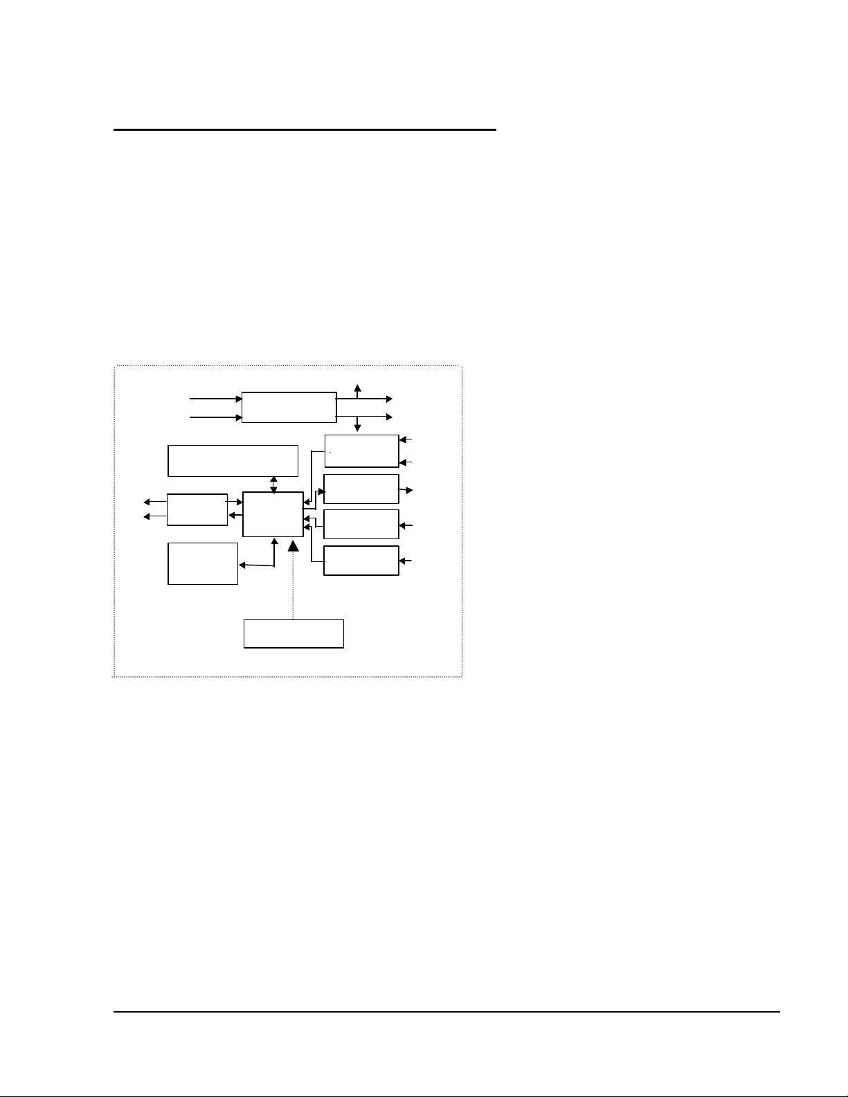
Functional Block Diagram of OMR-6012/D
+ 5V
+10V ~ +30V
Data +
Data -
Rec/Drv
Config Data
Regulator & Filter
Supervisor
Micro
Processor
LED Display
( only OMR-6012/D)
GND
ADC
Pin
1-8 Introduction
Page 12
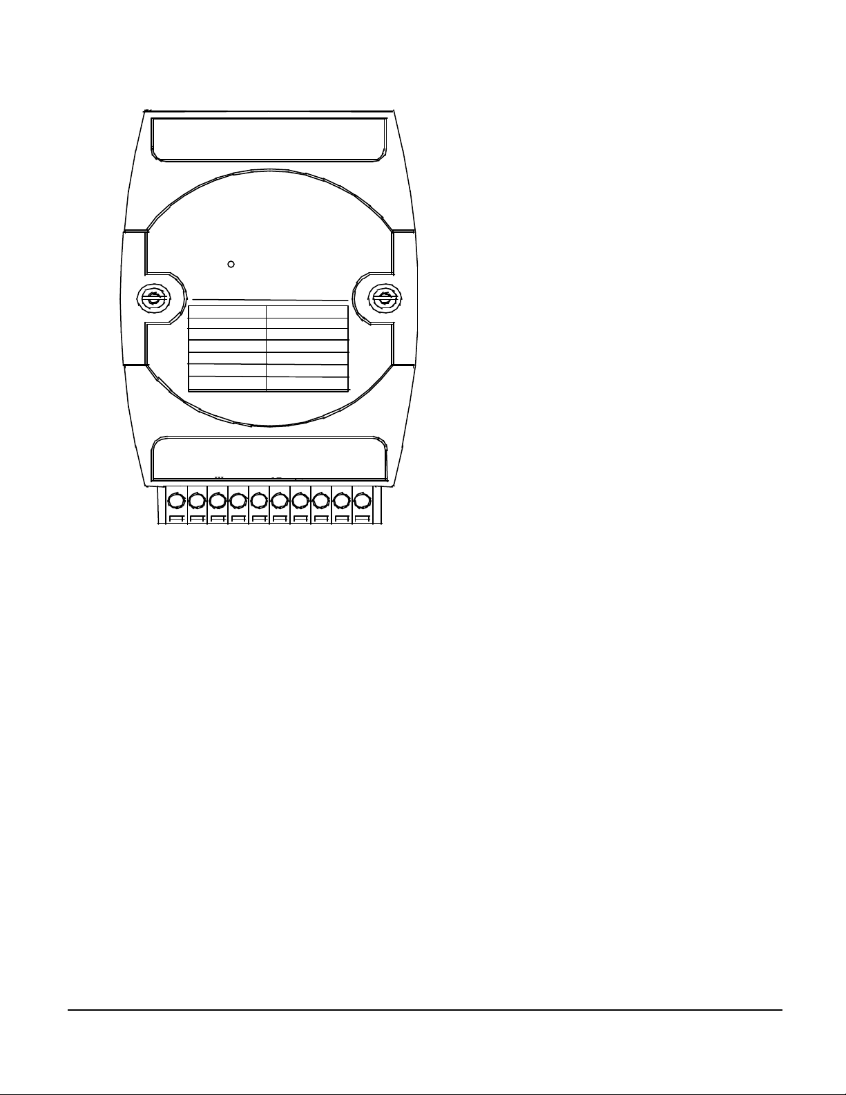
A Look at OMR-6012/D & Pin Assignment
Input
E
Code
mV/mA
11
20
OMR-6012
IN
IN
(+)
(-)
High Gain Analog
D
EF
A
U
10V
5 V
1 V
500 mV
150 mV
100 mV
0 - 20 mA
(Y
)D
A
T
(G
)D
A
T
(B)
10
(R
G
)+
N
08
09
0A
0B
0C
0D
D
D
DI
O
O
0/
0/
1/
Introduction 1-9
Page 13

1. 4. Overview of OMR-6013
What is OMR-6013 ?
OMR-6013 is a RTD input module with 3 input channels. It supports 2, 3 or 4 wires RTD input device.
Features of OMR-6013
• 3 RTD input channels
• 2, 3 or 4 wire RTD input support
• Programmable RTD input range
• Internal watchdog timer for device failure protection
• Easy programming by software
• Easy installation and wiring
Specifications of OMR-6013
² Interface
• Interface : RS-485, 2 wires
• Speed (bps) : 1200, 2400, 4800, 9600, 19.2K, 38.4K ,115.2K (115.2K only for firmware reversion above A4.00)
² RTD Input
• Input type: Pt or Ni input, 2, 3 or 4 wires
• Channels Numbers: 3
• Resolution: 16 bits
• Unit Conversion: °C or Ohm
• Temperature Range: Programmable 4 levels , ±100°C, 0~100°C, 0~200°C, 0~600°C
• Accuracy: ±0.1%
² Power
• Power supply : +10V to +30V
• Current consumption : 0.65 W
1-10 Introduction
Page 14
Pin Definitions of OMR-6013
2, 3, 4
Power
Data +
GND
RS-485
P ower Input
EEPROM
1-bit
3
Default*
Watchdog/Power
Pin # Signal Name Description
1 +IEXC0 Current source of CH0
2 +SENSE0 Differential positive input of CH0
3 -SENSE0 Differential negative input of CH0
4 -IEXC0 Current source of CH0
5 AGND0 Analog signal ground of CH0
6 DEFAULT* Initial state setting
7 (Y) DATA+ RS-485 series signal, positive
8 (G) DATA - RS-485 series signal, negative
9 (R) +Vs Power supply, +10V~+30V
10 (B) GND Ground
11 AGND2 Analog signal ground of CH2
12 -IEXC2 Current source of CH2
13 -SENSE2 Differential negative input of CH2
14 +SENSE2 Differential positive input of CH2
15 +IEXC2 Current source of CH2
16 AGND1 Analog signal ground of CH1
17 -IEXC1 Current source of CH1
18 -SENSE1 Differential negative input of CH1
19 +SENSE1 Differential positive input of CH1
20 +IEXC1 Current source of CH1
Functional Block Diagram of OMR-6013
+10V ~ +30V
Rec/Drv
Data -
Config Data
Safe Value
Regulator & Filter
Failure Supervisor
Micro
Processor
+ 5V
ADC
Digital Input
Mux
200µµ A
RTD
Input
Channels
200µµ A
+IEXC
+SENSE
-SENSE
-IEXC
GND
Wires
Pin
Introduction 1-11
Page 15
A Look at OMR-6013 & Pin Assignment
AGND 2
10
IEXC 0+
20
IEXC 1+
SENSE 1+
SENSE 1-
IEXC 1-
AGND 1
IEXC 2+
3-CH RTD Input
OMR-6013
αα =0.00385 αα =0.003916
Code Input Range Code Input Range
20 Pt.-100°C~+100°C 24 Pt.-100°C~+100°C
21 Pt. 0°C~+100°C 25 Pt. 0°C~+100°C
22 Pt. 0°C~+200°C 26 Pt. 0°C~+200°C
23 Pt. 0°C~+100°C 27 Pt. 0°C~+100°C
28 Ni-1000°C~+100°C 29 Ni-1200°C~+100°C
SENSE 0+
1
SENSE 0-
IEXC 0-
AGND 0
DEFAULT*
SENSE 2+
SENSE 2-
DATA +
DATA -
IEXC 2-
+Vs
11
GND
1-12 Introduction
Page 16

1. 5. Overview of OMR-6014D
What is OMR-6014D ?
OMR-6014D is a multi -functions analog(transmitter) input module with LED display. The programmable input voltage
range of analog input channel is from ±10V maximum to ±150mV minimum.
The module also provides the alarm function and the event counter just like OMR -6012/D. In fact, the OMR-6014D
provides almost all functions that OMR-6012/D has but there is more function with transmitter.
Features of OMR-6014D
• 1 analog input channel with differential input
• Programmable voltage range
• Self gain and offset calibration
• 2500 Vrms isolation voltage for AD channel
• 2 digital output channels of open collector type
• Alarm function with high / low alarm output
• 1 digital input channel / event counter
• Programmable host watchdog timer for host failure protection
• Internal watchdog timer for device failure protection
• Easy programming by software
• Easy installation and wiring
• 51/2 digital LED Display
Specifications of OMR-6014D
² Interface
• Interface : RS-485, 2 wires
• Speed (bps) : 1200, 2400, 4800, 9600, 19.2K, 38.4K ,115.2K (115.2K only for firmware reversion above A4.00)
² Analog Input
• Input type: Differential input
• Resolution: 16 bits
• Unit Convertion: mV, V, or mA
• Voltage Range: Programmable 5 levels
±10V, ±5V, ±1V, ±500mV, ±150mV
• Current Measurement: 20mA
• Accuracy: ±0.05%
• Isolation Voltage : 2500 Vrms
Introduction 1-13
Page 17

² Digital Output
• Channel numbers : 2
• Output characteristic : open collector transistor
• Maximum current sink : 50mA
• Max. power dissipation : 300mW
² Digital Input
• Channel numbers : 1
• Logical level 0 : +1V maximum
• Logical level 1: +2.0V~30V
• Pull up resister : 10KΩ
• Maximum current : 0.5mA
² Watchdog Function
• Module internal watchdog timer : 150 ms
• Power failure threshold : 4.65 V
• Host programmable watchdog : 100 ms ~ 25.500 sec
² Power
• Power supply : +10V to +30V
• Current consumption : 2.0 W
1-14 Introduction
Page 18
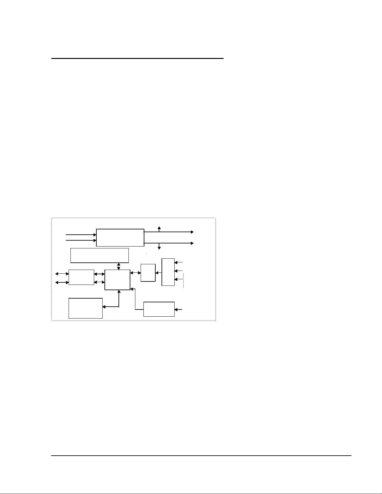
Pin Definitions of OMR-6014D
Power Input
Power
Regulator & Filter
RS-485
EEPROM
Safe Value
Watchdog/Power Failure
1-bit
Digital Input
1-bit
Digital Input
2-bits
Digital Output
DO0
Default*
ADC
Voltage
Input
Current
Input
VIN+
IIN+
LED DISPLAY
Pin # Signal Name Description
1 +15V External +15V
2 IIN+ Current Input Positive Terminal
3 IIN- Current Input Negative Terminal
6 DEFAULT* Initial state setting
7 (Y) DATA+ RS-485 series signal, positive
8 (G) DATA - RS-485 series signal, negative
9 (R) +Vs Power supply, +10V~+30V
10 (B) GND Ground
11 VIN- Analog Input Negative Terminal
12 VIN+ Analog Input Positive Terminal
13 +15V out External +15V Output
18 DO 0 / LO Digital Output Channel 0
or Low alarm output
19 DI 0 / EV Digital Input Channel 0
or event counter input
20 DO 1/ HI Digital Output Channel 1
or High alarm status output
Functional Block Diagram of OMR-6014D
+ 5V
+10V ~ +30V
Data +
Data -
Rec/Drv
Config Data
Supervisor
Processor
Micro
GND
VIN-
IIN-
DO1
DI0
Pin
Introduction 1-15
Page 19

A Look at OMR-6014D & Pin Assignment
VIN+
10
+15V out
±20mV
20
1
DO1/HI
DI0/EV
DO0/LO
OMR-6014D
Code mV/mA
08/09/0A
0B/0C/0D
IIN+
IIN-
Transmitter
Input Module
±
10V/25V/±1V
±500mV/
±150mV/
DEFAULT*
(Y)DATA+
(G)DATA-
+15V out
(R)+Vs
VIN-
(B)GND
1-16 Introduction
Page 20

1. 6. Overview of OMR-6017
What is OMR-6017 ?
OMR-6017 is an analog input module with 8 input channels. Six of the eight channels are differential type and the other
two are single ended type.
Features of OMR-6017
• 8 analog input channels
• 6 differential input and 2 single ended input
• programmable input voltage range
• Programmable host watchdog timer for host failure protection
• 5000 Vrms isolation voltage
• Internal watchdog timer for device failure protection
• Easy programming by software
• Easy installation and wiring
Specifications of OMR-6017
² Interface
• Interface : RS-485, 2 wires
• Speed (bps) : 1200, 2400, 4800, 9600, 19.2K, 38.4K ,115.2K (115.2K only for firmware reversion above A4.00)
² Analog Input1
• Input type: Differential input
• Channels Numbers: 8
• Resolution: 16 bits
• Unit Conversion: mV, V, or mA
• Voltage Range: Programmable 5 levels , ±10V, ±5V, ±1V, ±500mV, ±150mV
• Current Measurement: 20mA (with external 125Ω resistor)
• Accuracy: ±0.1%
² Power
• Power supply : +10V to +30V
• Current consumption : 1.2 W
Note1: The maximum input vo ltage shall not exceed to ±30V with reference to AGND otherwise, they may cause an
unrecoverable harm to the hardware component.
Introduction 1-17
Page 21
Pin Definitions of OMR-6017
Power Input
Power
Data +
GND
RS-485
Processor
EEPROM
1-bit
8
Default*
Watchdog/Power Failure
Pin # Signal Name Description
1 Vin5+ Differential positive input channel 5
2 Vin5- Differential negative input channel 5
3 Vin6+ Single-ended voltage input channel 6
4 AGND Analog signal ground of CH6 & 7
5 Vin7+ Single-ended voltage input channel 7
6 DEFAULT* Initial state setting
7 (Y) DATA+ RS-485 series signal, positive
8 (G) DATA - RS-485 series signal, negative
9 (R) +Vs Power supply, +10V~+30V
10 (B) GND Ground
11 Vin0+ Differential positive input channel 0
12 Vin0- Differential negative input channel 0
13 Vin1+ Differential positive input channel 1
14 Vin1- Differential negative input channel 1
15 Vin2+ Differential positive input channel 2
16 Vin2- Differential negative input channel 2
17 Vin3+ Differential positive input channel 3
18 Vin3- Differential negative input channel 3
19 Vin4+ Differential positive input channel 4
20 Vin4- Differential negative input channel 4
Functional Block Diagram of OMR-6017
+10V ~ +30V
Regulator & Filter
Supervisor
+ 5V
Mux
Digital Input
Analog
Input
Channels
Pin
Data -
Rec/Drv
Config Data
Safe Value
Micro
ADC
1-18 Introduction
Page 22
A Look at OMR-6017 & Pin Assignment
11
20
CODE
mV/ mA
Vi
Vi
n
n
Vi
Vi
n
n
Vi
Vi
n
n
Vi
Vi
Vi
n
n
n
Vi
n
Vi
n
OMR-6017
08
09
0A
0B
0C
0D
Vi
Vi
n
n
AGVi
n
8-CH Analog Input
10V
5 V
1 V
500 mV
150 mV
100 mV
0 - 20 mA
D
(Y
EF
A
U
(G
)D
)D
A
A
T
T
(B)
10
(R
G
)+
N
Introduction 1-19
Page 23

1. 7. Overview of OMR-6018
What is OMR-6018 ?
OMR-6018 is a thermocouple input module with 8 input channels. Six of the eight channels are differential type and the
other two are single ended type.
Features of OMR-6018
• 8 analog input channels
• 6 differential input and 2 single ended input
• programmable input voltage range
• Programmable host watchdog timer for host failure protection
• On board CJC for temperature measurement
• 2500 Vrms isolation voltage
• Internal watchdog timer for device failure protection
• Easy programming by software
• Easy installation and wiring
Specifications of OMR-6018
² Interface
• Interface : RS-485, 2 wires
• Speed (bps) : 1200, 2400, 4800, 9600, 19.2K, 38.4K ,115.2K (115.2K only for firmware reversion above A4.00)
² Analog Input1
• Input type: Differential input
• Channels Numbers: 8
• Resolution: 16 bits
• Unit Conversion: Thermocouple, mV, V or mA
• Thermocouple Type: J, K, T, E, R, S, B, N, C
J: 0°C~760°C K: 0°C~1000°C
T: -100°C~400°C E: 0°C~1000°C
R: 500°C~1750°C S: 500°C~1750°C
B: 500°C~1800°C N: -270°C~1300°C
C: 0°C~2320°C
• Voltage Range: Programmable 6 levels ±2.5V, ±1V, ±500mV, ±100mV, ±50mV, ±15mV
• Current Measurement: 20mA (with external 125Ω resistor)
1-20 Introduction
Page 24

² Power
• Power supply : +10V to +30V
• Current consumption : 0.9 W
Note1: The maximum input voltage shall not exceed to ±30V with reference to AGND otherwise, they may cause an
unrecoverable harm to the hardware component.
Introduction 1-21
Page 25
Pin Definitions of OMR-6018
Power Input
Power
Data +
GND
RS-485
Processor
EEPROM
1-bit
8
Default*
Watchdog/Power Failure
Pin # Signal Name Description
1 Vin5+ Differential positive input channel 5
2 Vin5- Differential negative input channel 5
3 Vin6+ Single-ended voltage input channel 6
4 AGND Analog signal ground of CH6 & 7
5 Vin7+ Single-ended voltage input channel 7
6 DEFAULT* Initial state setting
7 (Y) DATA+ RS-485 series signal, positive
8 (G) DATA - RS-485 series signal, negative
9 (R) +Vs Power supply, +10V~+30V
10 (B) GND Ground
11 Vin0+ Differential positive input channel 0
12 Vin0- Differential negative input channel 0
13 Vin1+ Differential positive input channel 1
14 Vin1- Differential negative input channel 1
15 Vin2+ Differential positive input channel 2
16 Vin2- Differential negative input channel 2
17 Vin3+ Differential positive input channel 3
18 Vin3- Differential negative input channel 3
19 Vin4+ Differential positive input channel 4
20 Vin4- Differential negative input channel 4
Functional Block Diagram of OMR-6018
Data -
+10V ~ +30V
Supervisor
Rec/Drv
Config Data
Safe Value
Regulator & Filter
Micro
ADC
Digital Input
+ 5V
Mux
Thermo-c
ouple
Input
channels
Pin
1-22 Introduction
Page 26

A Look at OMR-6018 & Pin Assignment
6018
Multiple
Vin 4+
20
Vin 4-
OMR-
ND-6017
Code mV/mA Code T/C
00 ±15mV 0E J Type
01 ±50mV 0F K Type
02 ±100mV 10 T Type
03 ±500mV 11 E Type
04 ±1V 12 R Type
05 ±2.5V 13 S Type
06 ±20mA 14 B Type
Vin 3-
CODE
08
09
0A
0B
0C
0D
Vin 3+
Vin 2-
8-CH Analog Input
Vin 1-
Vin 2+
Analog Input
mV/mA
10V
5 V
1 V
500 mV
100 mV
0 - 20 mA
Vin 1+
Vin 0-
11
Vin 0+
1
Vin 5+
Vin 5-
Vin 6+
AGND
Vin 7+
DEFAULT*
(G)DATA-
(Y)DATA+
(R)+Vs
10
(B)GND
Introduction 1-23
Page 27

2. Initialization & Installation
2. 1. Software Installation
1. If you have already installed “OMR Administration” then skip other steps.
2. Backup your software diskette.
3. Insert “OMR Administration” disc into CD-ROM:
4. Change drive to the path of CD-ROM. For example, your drive of CD-ROM is F:, then change the drive to F:
5. Find the setup of OMR Administration and run it.
6. Please follow the steps of setup program then you can successful to install the nudism Administration.
2. 2. Initializing a Brand New Module
Objective of Initializing a Brand New OMR
All OMR modules, except OMR -6520 and OMR -6510, in a RS-485 network must have an unique address ID. Every
brand new OMR has a factory default setting as following:
• Address ID is 01.
• Baud rate is 9600 bps
• Check-sum disable
• Host Watchdog timer is disable
Therefore, to configure the brand new OMR before using is necessary to avoid conflicting address. The baud rate may
also be changed according to user‘s requirements.
The initialization procedures of a brand new OMR are shown in the following sections. The procedures are applicable
for initializing OMR-6011/D, OMR-6012/D, OMR-6013, OMR-6014D, OMR-6017, and OMR-6018.
Initialization & Installation 2-1
Page 28

Default State
The OMR modules must be set at Default State when you want to change the default settings, including the ID address,
baud rate, check-sum status etc. All OMR modules have an special pin labeled as DEFAULT*. The module will be in
Default State if the Default*1 pin is shorted to ground when power ON. Under this state, the default configuration is set
as following:
• Address ID is 00.
• Baud rate is 9600 bps.
• Check-sum disable.
• Watchdog timer is disable.
Therefore, the configuration of the host and the module can be easily set identically and initializing a module will be
possible no matter what configuration is set under operating state.
Initialization Equipments
• Host computer with an RS-232 port.
• An installed RS-485 module (OMR-6520) with 9600 baud rate.
• The brand new OMR module
• Power supply (+10 VDC to +30 VDC) for OMR modules
• Administration utility software
Note1: Never Connect the DRFAULT* pin to Vs or power source just left it open or wired to GND.
2-2 Initialization & Installation
Page 29
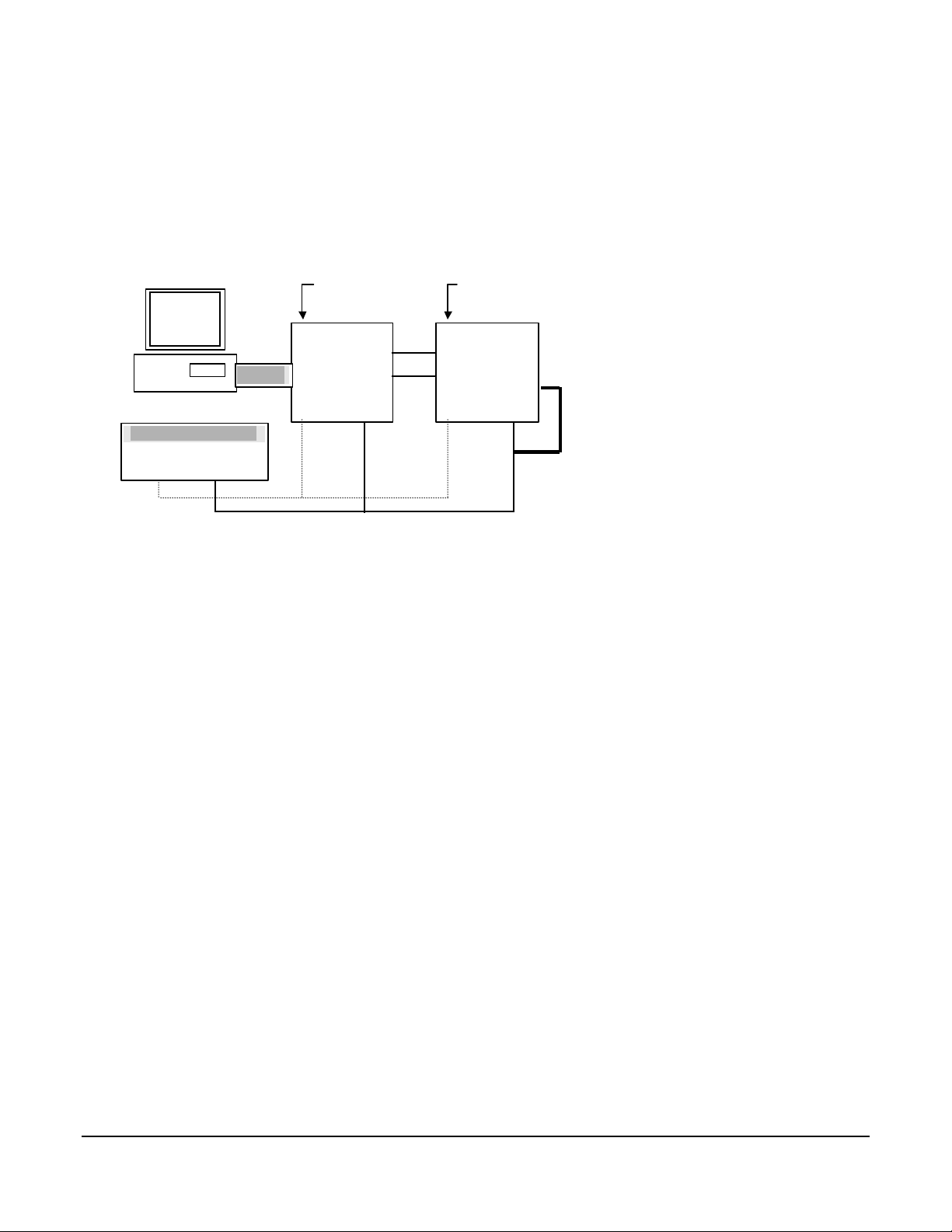
Initialization Procedure
Local Power Supply
New OMR
OMR-6520
1. Power off the host computer and the installed OMR-6520. Be sure of the baud rate of the OMR-6520 is 9600 bps.
2. Connect a brand new OMR module with the RS-485. Set the module in Default State by shorting the DEFAULT*
pin. Refer to Figure 2.1 for detailed wiring.
3. Power on the host computer.
4. Power on the power supply for OMR modules.
5. Use the OMR Administration utility to configure the address ID, Baud rate and check-sum status of the module.
Initialization Wiring
Host
Computer
+10 V to +30 V
+Vs GND
RS-232
RS-232/RS-485
Converter
DATA +
DATA -
module
DATA+
DATA -
Default*
+Vs G ND +Vs GND
Figure 2-1 Layout for Initialization the OMR module
Initialization & Installation 2-3
Page 30

2. 3. Install a New OMR to a Existing Network
Equipments for Install a New Module
• A existing OMR network
• New OMR modules.
• Power supply (+10 to +30 VDC).
Installing Procedures
1. Configure the new OMR module according to the initialization procedures in section 2.2.
2. The baud rate and check-sum status of the new module must be identity with the existing RS-485 network. The
address ID must not be conflict with other OMR modules on the network.
3. Power off the OMR power supply of the existing RS-485 network.
4. Power off the host computer.
5. Wire the power lines for the new OMR with the existing network. Be careful about the signal polarity as wiring.
6. Wire the RS-485 data lines for the new OMR with the existing network. Be careful about the signal polarity as
wiring.
7. Wire to the input or output devices. Refer to section 2.4 for illustrations.
8. Power on the host computer.
9. Power on the OMR local power supply.
10. Use the OMR administration utility to check entire network.
2-4 Initialization & Installation
Page 31

2. 4. Application Wiring for OMR-6011/D/6012/D/6013/6014D/6017/6018
Source
NuDAM-6011/6012/6017/6018
ADC
Source
OMR-6017/6018
Differential Analog Input Channel of
Differential Voltage Input
OMR-6011/D/6012/D/6017/6018
Differential
Signal
Differential Analog Input Channel of
IN(+)
IN(-)
Single Ended Voltage Input
Ground
Signal
Single Ended Input Channel of
IN(+)
ADC
AGND
Initialization & Installation 2-5
Page 32

Current Measurement
%1 accuracy
ADC
R
NuDAM-6011/6012/60176018
OMR-6011D/6012D Digital Input Channel
Micro Processor
TTL Buffer
Differential Input Channel of
Differential Input Channel of
OMR-6011/D/6012/D/6017/6018
Current
Source
R=125 Ohm
IN(+)
IN(-)
Digital Input Connect with TTL Signal
TTL
Device
DI 0
GND
+5V
To
2-6 Initialization & Installation
Page 33

Digital Input Used as an Event Counter
+Vs
OMR-6011/ 6012 Digital Input Channel
+5V
TTL Buffer
Clock
Source
DI 0
GND
Digital Output Connect with Power Loading
OMR-601x Digital Output Channel
From
Micro Processor
open
collector
DO n
GND
LED, SSR, Relay etc.
Power
Loading
R : current limit resistor
To
Micro Processor
R
External
Power
Supply
Initialization & Installation 2-7
Page 34

2 Wire
RTD Input (OMR-6013)
3 Wire
4 Wire
RTD
RTD
RTD
+IEXC 1
+SENSE
-SENSE
-IEXC
A.GND
+IEXC 1
+SENSE
-SENSE
-IEXC
A.GND
+IEXC 1
+SENSE
-SENSE
-IEXC
A.GND
2-8 Initialization & Installation
Page 35

Application Wiring for OMR-6014D
-
Millivolt and Volt Input
Process Current Input
+
Initialization & Installation 2-9
Page 36

Transmitter wiring for OMR-6014D
IN+
2-wire Transmitter Input
3-wire Transmitter Input
IN-
2-10 Initialization & Installation
Page 37

3. Command Set
3. 1. Command and Response
Introduction
The OMR command is composed by numbers of characteristics, including the leading code, address ID, the variables,
the optional check-sum bytes, and a carriage return to indicate the end of a command. The host computer can only
command only one OMR module except those synchronized commands with wildcard address “**”. The OMR may or
may not give response to the command. The host should check the response to handshake with the modules.
Document Conventions
The following syntax conventions describes the OMR commands in this manual.
(Leading Code) Leading Code is the first characteristic of the OMR
(Addr) Module’s address ID, the value is in the range of 00 (Command
Variable)
[Data] Some commands need additional data.
[Checksum] Checksum in brackets indicate optional parameter,
< > Identifies a control code character, such as <CR> for
command. All OMR commands need a command
leading code, such as %,$,#,@,...etc. 1- character
FF (Hex). 2- character
Command codes or value of variables.
Variable length
Variable length
only checksum is enable then this field is required. 2-
character
carriage return, its value is 0x0D.
1- character
Format of OMR Commands
(Leading Code)(Addr)(Command)[Data] [Checksum]<CR>
Command Set 3-1
Page 38

When checksum is enable then [Checksum] is needed, it is
2-character. Both command and response must append the checksum characters.
How to calculate checksum value ?
[Checksum] = ((LeadingCode)+(Addr)+(Command)+[Data]) MOD 0x100
Example 1: checksum is disable
User Command : $012<CR>
Response : !01400600<CR>
$ : LeadingCode
01 : Address
2 : Command (Read Configuration)
<CR> : Carriage return 0x0D
Example 2: checksum is enable
User Command : $012B7<CR>
Response : !01400600AC<CR>
$ : LeadingCode
01 : Address
2 : Command (Read Configuration)
B7 : Checksum value
<CR> : Carriage return 0x0D
‘$’ = 0x24 ‘0’ = 0x30 ‘1’ = 0x31 ‘2’ = 0x32
B7 = ( 0x24 + 0x30 + 0x31 + 0x32 ) MOD 0x100
‘!’ = 0x24 ‘0’ = 0x30 ‘1’ = 0x31 ‘4’ = 0x34
‘6’ = 0x36
AC = ( 0x24 + 0x30 + 0x31 + 0x34 + 0x30 + 0x30 + 0x36 + 0x30 + 0x30 ) MOD 0x100
Note : 1. There is no spacing between the command words and
The checksum characters.
2. Every command follows a <CR> carriage return for
ending.
3. The checksum characters are optional.
Response of OMR Commands
The response message depends on versatile OMR command. The response is composed with a few characteristics,
including leading code, variables, and carriage return for ending. There are two categories of leading code for response
message, ”!“ or ”>“ means valid command and ”?“ means invalid. By checking the response message, user can monitor
the command is valid or not.
Note : Under the following conditions, there will have no response message.
1. The specified address ID is not exist.
2. Syntax error.
3. Communication error.
4. Some special commands do not have response.
3-2 Command Set
Page 39

3. 2. Summary of Command Set
There are three categories of OMR commands. The first is the general commands, including set configuration
command, read configuration, reset, read module‘s name or firmware version, etc. Eve ry OMR can response to the
general commands. The second is the functional commands, which depends on functions of each module. Not every
module can execute all function commands. The third is the special commands including functions about the
programmable watchdog timer, safe values, and the programmable leading code. All the commands used in the OMR
analog input module are list in the following table.
Command Set of Analog Input Modules
Command Syntax Modules Page
General Commands
%(OldAddr)(NewAddr)
Set Configuration
(InputRange)(BaudRate)
(DataFormat)
Read Configuration $(Addr)2 ALL 3-12
Read Module Name $(Addr)M ALL 3-13
Read Firmware Version $(Addr)F ALL 3-14
Functional Commands
Synchronized Sampling #**
Read Synchronized
Analog Data
$(Addr)4
Read Analog Data #(Addr)
Read Analog Data
Channel 0
#(Addr) 6013 3-18
Span Calibration $(Addr)0
Span Calibration to each
Channel
$(Addr)0(Channel No) 6013 3-20
ALL 3-8
6011/D,
6012/D,
6014D
6011/D,
6012/D,
6014D
6011/D,
6012/D,
6014D
6011/D,
6012/D,
6014D,
6017,
6018
3-15
3-16
3-18
3-19
Command Set 3-3
Page 40

Offset Calibration $(Addr)1
Offset Calibration to
each Channel
Read Analog Data From
Channel N
Read All Analog Data $(Addr)A
Enable/Disable Channel
for Multiplexing
Read Channel Status $(Addr)6
Read CJC Status $(Addr)3
6011/D,
6012/D,
6014D,
6017,
6018
3-21
#(Addr)1(Channel No) 6013 3-22
#(Addr)(ChannelNo)
$(Addr)5(ChannelVal)
6013,
6017,
6018
6013,
6017,
6018
6013,
6017,
6018
6013,
6017,
6018
6011/D,
6018
3-23
3-24
3-25
3-26
3-27
Open Thermocouple
Detection of Channel N
Enable/Disable Open
Thermocouple Detection
$(Addr)B(ChannelNo) 6018 3-28
$(Addr)O(Status) 6018 3-30
Read Source High/Low
Values for Linear
$(Addr)3 6014D 3-31
Mapping
Read Target High/Low
Values for Linear
$(Addr)5 6014D 3-32
Mapping
Write Source High/Low
Values for Linear
Mapping
Write Target High/Low
Values for Linear
Mapping
Enable/Disable Linear
Mapping
Read Enable/Disable
Linear Mapping Status
CJC Offset Calibration $(Addr)9(Counts)
Clear Latch Alarm @(Addr)CA
Clear Event Counter @(Addr)CE
Disable Alarm @(Addr)DA
Read Digital I/O and
Alarm Status
$(Addr)6(Data_L)(Data_
H)
$(Addr)7(Data_L)(Data_
H)
6014D 3-33
6014D 3-35
$(Addr)A(Status) 6014D 3-37
$(Addr)R 6014D 3-38
6011/D,
6018
6011/D,
6012/D,
6014D
6011/D,
6012/D,
6014D
6011/D,
6012/D,
6014D
6011/D,
@(Addr)DI
6012/D,
6014D
Set Digital Output @(Addr)DO(OutData) 6011/D,
3-39
3-40
3-41
3-42
3-43
3-45
3-4 Command Set
Page 41

Enable Alarm @(Addr)EA(Mode)
Set High Alarm @(Addr)HI(Data)
Set Low Alarm @(Addr)LO(Data)
Read Event Counter @(Addr)RE
Read High Alarm @(Addr)RH
Read Low Alarm @(Addr)RL
Special Commands
6012/D,
6014D
6011/D,
6012/D,
6014D
6011/D,
6012/D,
6014D
6011/D,
6012/D,
6014D
6011/D,
6012/D,
6014D
6011/D,
6012/D,
6014D
6011/D,
6012/D,
6014D
3-46
3-47
3-48
3-49
3-50
3-51
Read Command Leading
Code Setting
Change Command
Leading Code Setting
Set Host Watchdog /
Safety Value
Read Host WatchDog /
Safe Value
~(Addr)0 ALL 3-52
~(Addr)10(C1)(C2)(C3)
(C4)(C5)(C6)
~(Addr)2(Flag)
(TimeOut)(SafeValue)
ALL 3-54
ALL 3-56
~(Addr)3 ALL 3-58
Host is OK ~** ALL 3-60
Note: “ALL” means for OMR-6011/D, OMR-6012/D, OMR-6013, OMR-6014D, OMR-6017 and OMR-6018.
Command Set 3-5
Page 42

3. 3. Set Configuration
(6011/D, 6012/D, 6013
6014D, 6017, 6018)
@Description
Configure the basic setting of OMR, including the address ID, input range, baud rat e, and data format. The new
configuration will be available after executing the command.
@Syntax
%(OldAddr)(NewAddr)(InputRange)(BaudRate)(DataFormat)<CR>
% Command leading code. (1-character)
(OldAddr) OMR module original address ID. The default
addres s ID of a brand new module is 01. The
value range of address ID is 00 to FF in
hexadecimal.
(NewAddr) New address ID, if you don’t want to change
(InputRange) Define analog input range, refers to Table 3-1
(BaudRate) Define communication baud rate, refers to
(DataFormat) Define checksum, integration time and output
(2-character)
address ID, let new address ID equals to the
old one. (2-character)
for details. (2-character)
Table 3-2 for details. (2-character)
data format, refers to Figure 3-1 for details.
(2-character)
@Response
!(Addr)<CR>
or
?(Addr)<CR>
(Addr)
! Command is valid.
? Command is invalid, parameter values are invalid, or
Address ID.
change the setting without grounding the DEFAULT*
pin.
3-6 Command Set
Page 43

Note : 1. When you want to change the checksum or baud rate,
the DEFAULT* pin must be grounded at first.
2. Waiting a maximum of 7 seconds to perform auto
calibration and ranging after the analog input module is
reconfigured. Please don’t execute any other command
during this time period.
@Example
User command: %0130050600<CR>
Response: !30<CR>
Item Meaning Description
% (Leading Code) Command leading code.
01 (OldAddr) Original address ID is 01(Hex).
30 (NewAddr) New address ID is 30(Hex).
05 (InputRange)
06 (BaudRate) Baud rate is 9600.
00 (DataFormat) 00 means data format is engineering
<CR> Carriage return 0x0D.
Analog input range is ±2.5V
units, checksum is disable and
integration time is 50 ms (60Hz).
Command Set 3-7
Page 44

Code (Hex) Input Range Modules
00
01
02
03
04
05
06
08
09
0A
0B
0C
0D
0E
0F
10
11
12
13
14
15
16
20
21
22
23
24
25
26
27
28
29
±15 mV
±50 mV
±100 mV
±500 mV
±1 V
±2.5 V
±20 mA
(Required 125Ω current conversion resistor.)
±10 V
±5 V
±1 V
±500 mV
±150 mV
±20 mA
(Required 125Ω current conversion resistor.)
Type J Thermocouple 0° to 760°C
Type K Thermocouple 0° to 1000°C
Type T Thermocouple -100° to 400°C
Type E Thermocouple 0° to 1000°C
Type R Thermocouple 500° to 1750°C
Type S Thermocouple 500° to 1750°C
Type B Thermocouple 500° to 1800°C
Type N Thermocouple -270° to 1300°C
Type C Thermocouple 0° to 2320°C
Pt-100, -100°C to +100°C, α=0.00385
Pt-100, 0°C to +100°C, α=0.00385
Pt-100, 0°C to +200°C, α=0.00385
Pt-100, 0°C to +600°C, α=0.00385
Pt-100, -100°C to +100°C, α=0.003916
Pt-100, 0°C to +100°C, α=0.003916
Pt-100, 0°C to +200°C, α=0.003916
Pt-100, 0°C to +600°C, α=0.003916
Ni-100, 0°C to +100°C
Ni-120, 0°C to +100°C
6011/D,6018
6011/D,6018
6011/D,6018
6011/D,6018
6011/D,6018
6011/D,6018
6011/D,6018
6012/D,6017,
6014D
6012/D,6017,
6014D
6012/D,6017,
6014D
6012/D,6017,
6014D
6012/D,6017,
6014D
6012/D,6017,
6014D
6011/D,6018
6011/D,6018
6011/D,6018
6011/D,6018
6011/D,6018
6011/D,6018
6011/D,6018
6011/D,6018
6011/D,6018
6013
6013
6013
6013
6013
6013
6013
6013
6013
6013
3-8 Command Set
Table 3-1 AD Input Range Setting
Code Baudrate
03 1200 bps
04 2400 bps
05 4800 bps
06 9600 bps
07 19200 bps
08 38400 bps
09 115200 bps
Table 3-2 Baud rate setting code
Reserved
Must to be 0
Page 45

Checksum
Analog Input Data Format
7 6 5 4 3 2 1 0
0 : disable
1 : enable
00 : Engineering units
01 : % of Full Scale Range
10 : Two’s complement of hexadecimal
11 : Ohms (6013 only)
Note :
6017/6018 only support engineering
units.
6013 supports engineering units and
ohms display.
Figure 3-1 Data Format Setting of Analog Input Modules
Command Set 3-9
Page 46

3. 4. Read Configuration
(6011/D, 6012/D, 6013
@Description
Read the configuration of module on a specified address ID.
@Syntax
$(Addr)2<CR>
$ Command leading code
(Addr) Address ID.
2 Command code for reading configuration
@Response
!(Addr)(InputR ange)(BaudRate)(DataFormat)<CR>
or
?(Addr)<CR>
!
? Command is invalid.
(Addr) Address ID.
(InputRange) Current setting of analog voltage input, refers
(BaudRate) Current setting of communication baud rate,
(DataFormat) Current settings of checksum, integration time
Command is valid.
to Table 3-1 for details.
refers to Table 3-2 for details.
and output data format, refers to Figure 3-1 for
details.
6014D, 6017, 6018)
@Example
User command: $302<CR>
Response: !30050600<CR>
! Command is valid.
30 Address ID.
05
06 Baud rate is 9600 bps.
00 checksum is disable.
Analog input range is ±2.5 V.
3-10 Command Set
Page 47

3. 5. Read Module Name
(6011/D, 6012/D, 6013
@Description
Read module name of OMR at specified address.
@Syntax
$(Addr)M<CR>
$ Command leading code.
(Addr) Address ID
M Read module name
@Response
!(Addr)(ModuleName) <CR>
or
?(Addr)<CR>
!
? Command is invalid.
(Addr) Address ID.
(ModuleName) OMR module‘s name could be ‘6011’, ’6011/D‘,
@Example
User command: $30M<CR>
Response: !306011/D<CR>
! Command is valid.
30 Address
6011/D OMR-6011/D (Analog Input Module)
Command is valid.
‘6012’, ’6012/D‘, ‘6013’, ‘6017’
or ’6018‘.
4 or 5 characters
6014D, 6017, 6018)
Command Set 3-11
Page 48

3. 6. Read Firmware Version
(6011/D, 6012/D, 6013
@Description
Read firmware version of OMR at specified address.
@Syntax
$(Addr)F<CR>
$ Command leading code.
(Addr) Address ID
F Read module firmware version.
@Response
!(Addr)(FirmRev) <CR>
or
?(Addr)<CR>
! Command is valid.
? Command is invalid.
(Addr) Address ID.
(FirmRev) OMR module‘s firmware version.
@Example
User command: $30F<CR>
Response: !30A2.10<CR>
! Command is valid.
30 Address
A2.10 Firmware Version
6014D, 6017, 6018)
3-12 Command Set
Page 49

3. 7. Synchronized Sampling
(6011/D, 6012/D, 6014D)
@Description
Synchronized all modules to sample analog input values and stored the values in the module’s register at the same
time. The sampled data can be read by “Read Synchronized Data” command.
@Syntax
#**<CR>
# Command leading code.
** Synchronized sampling command
@Response
Note : Synchronized sampling command has NO response.
@Example
User command: #**<CR>
Command Set 3-13
Page 50

3. 8. Read Synchronized Data
(6011/D, 6012/D, 6014D)
@Description
After a synchronized sampling command #** was issued, you can read the sampled value that was stored in the register
of the module at specified address.
@Syntax
$(Addr)4<CR>
$ Command leading code.
(Addr) Address ID
4 Read synchronized data.
@Response
>(Addr)(Status)(Data)<CR>
or
?(Addr)<CR>
>
? Command is invalid or no synchronized sampling
(Addr) Address ID.
(Status) 0 : Data has been sent at least once before.
(Data) There are four types of Data format, refers to
Command is valid.
command was issued.
1 : Data has been sent for the first time since a
synchronized sampling command was
issued. (1-character)
Chapter 4 for details.
3-14 Command Set
Page 51

@Examples
User command: $064<CR>
Response: >060+1.6888<CR>
Read synchronized data at address 06H, analog input modul e send its analog input data +1.6888 (units). Status is 0
means it has sent the same data at least once. The current units is set by the data format.
User command: $064<CR>
Response: >061+1.6888<CR>
Read synchronized data at address 06H, analog input module send its analog input data +1.6888 (units). Status is 1
means it is the first time that the data has been sent. The current units is set by the data format
Command Set 3-15
Page 52

3. 9. Read Analog Data
(6011/D, 6012/D, 6013, 6014D)
@Description
Read the analog input value from an analog input module at specified address in a OMR network. While for OMR-6013,
it returns the channel 0 analog data.
@Syntax
#(Addr)<CR>
# Command leading code
(Addr) Address ID
@Response
>(InputData)<CR>
>
(InputData) The input data represents the analog signal. The
@Example
User command: #06<CR>
Response: >+1.6888<CR>
Read the analog input module data at address 06 (Hex). The analog input module response data is +1.6888 units. The
unit depends on the data format.
Delimiter character
unit of the digits depends on the data format used.
There are four types of data format. The format is
set by the set configuration command.
3-16 Command Set
Page 53

3. 10. Span Calibration
(6011/D, 6012/D
6014D, 6017, 6018)
@Description
To correct the gain errors of AD converter by using the span calibration.
@Syntax
$(Addr)0<CR>
$ Command leading code (1 character)
(Addr) Address ID (2 character)
0 Span calibration (1 character)
@Response
!(Addr)<CR>
or
?(Addr)<CR>
! Command is valid.
? Command is invalid.
(Addr) Address ID.
@Example
User command: $060<CR>
Response: !06<CR>
To perform the span calibration for analog input module, address ID is 06H.
Note : To perform the calibration, a proper input signal should be connected to the analog input module. Different input
range have different input voltage, detail refer chapter 5 “Calibration”.
Command Set 3-17
Page 54

3. 11. Span Calibration to each Channel
(6013)
@Description
To correct the gain errors of AD converter by using the span calibration.
@Syntax
$(Addr)0(Channel No)<CR>
$ Command leading code (1 character)
(Addr) Address ID (2 character)
0 Span calibration (1 character)
(Channel No) Channel for Calibration (1 character) 0~2
@Response
!(Addr)<CR>
or
?(Addr)<CR>
! Command is valid.
? Command is invalid.
(Addr) Address ID.
@Example
User command: $0601<CR>
Response: !06<CR>
To perform the span calibration for analog input module OMR-6013 channel 1, address ID is 06H.
Note : To perform the calibration, a proper input signal should be connected to the analog input module. Different input
range have different input voltage, detail refer chapter 5 “Calibration” .
3-18 Command Set
Page 55

3. 12. Offset Calibration
(6011/D, 6012/D
6014D, 6017, 6018)
@Description
To correct the offset errors of AD converter by using the offset calibration.
@Syntax
$(Addr)1<CR>
$ Command leading code
(Addr) Address ID
1 Offset calibration.
@Response
!(Addr)<CR>
or
?(Addr)<CR>
! Command is valid.
? Command is invalid.
(Addr) Address ID.
@Example
User command: $061<CR>
Response: !06<CR>
To perform the offset calibration for analog input module at specified address 06 (Hex).
Note : To perform the calibration, a proper input signal should be connected to the analog input module. Different input
range have different input voltage, detail refer chapter 5 “Calibration” .
Command Set 3-19
Page 56

3. 13.Offset Calibration to each Channel
(6013)
@Description
To correct the offset errors of AD converter by using the offset calibration.
@Syntax
$(Addr)1(Channel No)<CR>
$ Command leading code
(Addr) Address ID
1 Offset calibration.
(Channel No) Channel for calibration. (1 character)0~2
@Response
!(Addr)<CR>
or
?(Addr)<CR>
! Command is valid.
? Command is invalid.
(Addr) Address ID.
@Example
User command: $0612<CR>
Response: !06<CR>
To perform the offset calibration for analog input module OMR-6013 channel 2 at specified address 06 (Hex).
Note : To perform the calibration, a proper input signal should be connected to the analog input module. Different input
range have different input voltage, detail refer chapter 5 “Calibration” .
3-20 Command Set
Page 57

3. 14. Read Analog Data From Channel N
(6013, 6017, 6018)
@Description
Read the analog input value of a specified AD channel from an analog input module at specified address in a OMR
network.
@Syntax
#(Addr)(ChannelNo)<CR>
# Command leading code. (1-character)
(Addr) Address ID. (2-character)
(ChannelNo) Channel number, range (0 - 7). (1-character)
Range (0-2). For OMR-6013
@Response
>(InputData)<CR>
>
(InputData) Input value from a specified channel number, the
@Example
User command: #061<CR>
Response: >+1.6888<CR>
Read the ana log input channel 1 of AD module at address 06 (Hexadecimal) in the network. The analog input data is
+1.6888 Volts (Data format is engineering unit)
Delimiter character
data format is a + or - sign with five decimal digits
and a fixed decimal point.
Command Set 3-21
Page 58

3. 15. Read All Analog Data Channel
(6013, 6017, 6018)
@Description
Read all the enable analog input channel value of a specified from an analog input module at specified address in a
OMR network.
@Syntax
#(Addr)A<CR>
# Command leading code. (1-character)
(Addr) Address ID. (2-character)
A All the enable channel
@Response
>(InputData)(InputData)(InputData)<CR>
> Delimiter character
(InputData) Input value from a specified channel number, the
data format is a + or - sign with five decimal digits
and a fixed decimal point.
@Example
User command: #06A<CR>
Response: >+100.88+020.66+006.79<CR>
Read the analog input of AD modul e at address 06 (Hexadecimal) in the network. The analog input data are +100.88 °C
for channel 0, +020.66 °C for channel 1 and +006.79°C for channel 3. (Data format is engineering unit)
3-22 Command Set
Page 59

3. 16. Enable/Disable channels for Multiplexing
(6013, 6017, 6018)
@Description
Enable/Disable multiplexing simultaneously for individual channel.
@Syntax
$(Addr)5(ChannelVal)<CR>
$ Command leading code. (1-character)
(Addr) Address ID (2-character)
5 Enable/Disable channel. (1-character)
(ChannelVal) bit 3~0 of 1st character: control channel 7 - 4.
@Response
!(Addr)<CR>
or
?(Addr)<CR>
! Command is valid.
? Command is invalid.
(Addr) Address ID.
@Example
User command: $06548<CR>
Response: !06<CR>
$
06 Address ID.
5 Disable/Enable channel.
48 Channel Value is 0x48.
bit 3~0 of 2nd character: control channel 3 - 0.
bit value 0 : Disable channel
bit value 1 : Enable channel (2-character)
Command leading code.
‘48’ is 01001000 that means enable channel 3 and
channel 6, the other channels are all disable.
Command Set 3-23
Page 60

3. 17. Read Channel Status
(6013, 6017, 6018)
@Description
Read the enable/disable status the channels of OMR-6013, OMR-6017 or 6018.
@Syntax
$(Addr)6<CR>
$ Command leading code. (1-character)
(Addr) Address ID (2-character)
6 Read channel status. (1-character)
@Response
!(Addr)(ChannelVal)<CR>
or
?(Addr)<CR>
!
? Command is invalid.
(Addr) Address ID.
(ChannelVal) bit 3~0 of 1st character: controlt channel 7 - 4.
Command is valid.
bit 3~0 of 2nd character: control channel 3 - 0.
bit value 0 : Disable channel
bit value 1 : Enable channel (2-character)
@Example
User command: $066<CR>
Response: !0648<CR>
4 is equals binary 0100 that means enable channel 6 and disable channel 7, 5, 4.
8 is equals binary 1000 that means enable channel 3 and disable channel 2, 1, 0.
3-24 Command Set
Page 61

3. 18. Read CJC Status
(6011/D, 6018)
@Description
Read the CJC (Cold Junction Compensation) sensors data.
@Syntax
$(Addr)3<CR>
$ Command leading code.
(Addr) Address ID
3 Read CJC status.
@Response
>(Data)<CR>
or
?(Addr)<CR>
>
(Data) CJC sensor’s data.
? Command is invalid.
(Addr) Address ID.
@Example
User command: $063<CR>
Response: >+0037.9<CR>
This command is to read analog input module CJC stat us at address 06H, return data is 37.9°C.
Command is valid.
Data format is engineering units. (an + or - sign with
five decimal digits and a decimal fixed point. The
resolution is 0.1°C
Command Set 3-25
Page 62

3. 19. Read Open Thermocouple Detection of Channel N
(6018)
@Description
Read the status of open thermocouple from specified channel number or all channel.
@Syntax
$(Addr)B(ChannelNo)<CR>
$ Command leading code.
(Addr) Address ID
B Open thermocouple detection command code
ChannelNo Channel number, range( 0-7) for specified channel,
@Response
!(Addr)(OpSts)<CR>
or
?(Addr)<CR>
!
(Addr) Address ID
(OpSts) For specified channel ( 0-7) (1 character)
? Command is invalid.
A for all the channel
Command is valid.
0 : Close thermocouple
1 : Open thermocouple
For all the channel ( 00-FF) (2 character)
Two character hexadecimal value, for bit 0-7
Representing the corresponding open thermocouple
status channel 0-7.
3-26 Command Set
Page 63

@Example
User command: $01B0<CR>
! Command is valid.
! Command is valid.
FE Open thermocouple of channel 1~7
Close thermocouple of channel 0
Notice: The open detection function is immediate scanning by hardware
every 500ms. Disable channel and input out of high temperature
range will be recognized as open T/C.
Response: !011<CR>
01 Address ID.
1 Open thermocouple of channel 0
User command: $01BA<CR>
Response: !1FE<CR>
01 Address ID.
Command Set 3-27
Page 64

3. 20.Enable/Disable Open
Thermocouple Detection
@Description
Enable and disable the open thermocouple detection function.
@Syntax
$(Addr)O(Status)<CR>
$ Command leading code.
(Addr) Address ID
O Enable/Disable Open thermocouple detection
command
(Status) 0: Disable Open thermocouple detection
1: Enable Open thermocouple detection
@Response
!(Addr)<CR>
or
?(Addr)<CR>
!
(Addr) Address ID.
? Command is invalid.
@Example
User command: $05O0<CR>
Response: ! 05<CR>
This command is to disable Open thermocouple detection.
User command: $05O1<CR>
Response: ! 05<CR>
This command is to enable Open thermocouple detection.
Command is valid.
(6018)
3-28 Command Set
Page 65

3. 21. Read Source High/Low Values for Linear Mapping
(6014D)
@Description
Read the high/low limit values from input for linear mapping.
@Syntax
$(Addr)3<CR>
$ Command leading code.
(Addr) Address ID
3 Read the high/low limit values from input for linear
mapping .
@Response
!(Addr)(Data_L)(Data_H)<CR>
or
?(Addr)<CR>
!
(Addr) Address ID.
(Data_L) Low limit value for linear mapping.
(Data_H) High limit value for linear mapping.
? Command is invalid.
Command is valid.
Data format is with an + or - sign with five decimal
digits and a decimal fixed point.
Data format is with an + or - sign with five decimal
digits and a decimal fixed point.
@Example
User command: $023<CR>
Response: !02+04.000+20.000<CR>
The module is configured for +20~-20mA input current range. The linear mapping function should already have been
executed. This command is to read the high/low values for linear mapping. The high limit value is +20mA and low limit
value is +4mA. The address of this module is 06H.
Command Set 3-29
Page 66

3. 22.Read Target High/Low Values for Linear Mapping
(6014D)
@Description
Read the mapped high/low limit values from input for linear mapping.
@Syntax
$(Addr)5<CR>
$ Command leading code.
(Addr) Address ID
5 Read the mapped high/low limit values from input for
linear mapping .
@Response
!(Addr)(Data_L)(Data_H)<CR>
or
?(Addr)<CR>
!
(Addr) Address ID.
(Data_L) Mapped low limit value for linear mapping.
(Data_H) Mapped high limit value for linear mapping.
? Command is invalid.
Command is valid.
Data format is with an + or - sign with five decimal
digits and a decimal fixed point.
Data format is with an + or - sign with five decimal
digits and a decimal fixed point.
@Example
User command: $055<CR>
Response: !05-20.000+20.000<CR>
The module is configured for +20~-20mA input current range. The linear mapping function had been executed. This
command is to read the mapped high/low values for linear mapping. The mapped high limit value is +20 mA and mapped
low limit value is -20mA. The address of this module is 05H.
3-30 Command Set
Page 67

3. 23.Write Source High/Low Values for Linear Mapping
(6014D)
@Description
Write the source high/low limit values from input for linear mapping.
@Syntax
$(Addr)6(Data_L)(Data_H)<CR>
$ Command leading code.
(Addr) Address ID
6 Set the high/low limit values from input for linear
(Data_L) Low limit input value for linear mapping. It must be
(Data_H) High limit input value for linear mapping. It must be
mapping .
lower than the high limit input value. The format of
data is the same as input current range. The
minimum input value could equal to the minimum
input value of input current range. Data format is with
an + or - sign with five decimal digits and a decimal
fixed point.
higher than the low limit input value. The format of
data is the same as input current range. The
maximum input value could equal to the maximum
input value of input current range. Data format is with
an + or - sign with five decimal digits and a decimal
fixed point.
@Response
!(Addr)<CR>
or
?(Addr)<CR>
!
(Addr) Address ID.
? Command is invalid.
Command is valid.
Command Set 3-31
Page 68

@Example
User command: $036-100.00+100.00<CR>
Response: !03<CR>
The module is configured for +150~-150mV input range. This command is to set the input high/low values from
+100.00 to –100.00mV for linear mapping. The address of this module is 05H.
3-32 Command Set
Page 69

3. 24.Write Target High/Low Values for Linear Mapping
(6014D)
@Description
Write the target high/low limit values from input for linear mapping.
@Syntax
$(Addr)7(Data_L)(Data_H)<CR>
$ Command leading code.
(Addr) Address ID
7 Set the mapped high/low limit values from input for
(Data_L) Mapped low limit input value for linear mapping. It
(Data_H) Mapped high limit input value for linear mapping. It
linear mapping .
must be lower than the mapped high limit input
value. Data format is with an + or - sign with five
decimal digits and a decimal fixed point.
must be Higher than mapped the low limit input
value. Data format is with an + or - sign with five
decimal digits and a decimal fixed point.
@Response
!(Addr)<CR>
or
?(Addr)<CR>
!
(Addr) Address ID.
? Command is invalid.
Command is valid.
@Example
User command: $036-100.00+100.00<CR>
Response: !03<CR>
The module is configured for +150~-150mV input range. This command is to set the input high/low values from
+100.00 to –100.00mV for linear mapping. The address of this module is 03H.
Command Set 3-33
Page 70

3. 25.Enable/Disable Linear Mapping
@Description
Enable or disable the linear mapping function for the module.
@Syntax
$(Addr)A(Status)<CR>
$ Command leading code.
(Addr) Address ID
A Reference to control the linear mapping function.
(Status) One char to determine the linear mapping function
@Response
!(Addr)<CR>
or
?(Addr)<CR>
!
(Addr) Address ID.
? Command is invalid.
@Example
User command: $03A1<CR>
Response: !03<CR>
This command set the linear mapping function of OMR-6014D is enable, and the address of this module is 03H.
enable or disable.
1: means enable.
0: means disable.
Command is valid.
(6014D)
3-34 Command Set
Page 71

3. 26.Read enable/Disable Linear
Mapping Status
@Description
Read enable or disable the linear mapping status for the module.
@Syntax
$(Addr)R<CR>
$ Command leading code.
(Addr) Address ID
R Read to the linear mapping status.
@Response
!(Addr)(Status)<CR>
or
?(Addr)<CR>
!
(Addr) Address ID.
(Status) One char to means the state of linear mapping.
? Command is invalid.
@Example
User command: $07R<CR>
Response: !070<CR>
This command means the linear mapping function of OMR-6014D is disable, and the address of this module is 07H.
Command is valid.
1: means enable.
0: means disable.
(6014D)
Command Set 3-35
Page 72

3. 27.CJC Offset Calibration
(6011/D, 6018)
@Description
To correct the CJC offset errors use CJC (Cold Junction Compensation) offset calibration.
@Syntax
$(Addr)9(Counts)<CR>
$
(Addr) Address ID
9 CJC offset calibration.
(Counts) It is a 4-characters (Hexadecimal) with a sign + or -,
Command leading code.
range is 0000 to FFFF, each count equals
approximately 0.0153°C.
Example : +0042 = 4x16 + 2 = 66
66 * 0.0153°C = 1.009°C
@Response
!(Addr)<CR>
or
?(Addr)<CR>
! Command is valid.
? Command is invalid.
(Addr) Address ID.
@Example
User command: $089+0042<CR>
Response: !08<CR>
CJC offset calibration at address 08H. The calibrated offset temperature is +0042(Hex) = 66, 66 x 0.0153°C = 1.009°C
3-36 Command Set
Page 73

3. 28. Clear Latched Alarm
(6011/D, 6012/D, 6014D)
@Description
Clear the High/Low alarm state at specified analog input module.
@Syntax
@(Addr)CA<CR>
@ Command leading code.
(Addr) Address ID
CA Clear latched alarm.
@Response
!(Addr)<CR>
! Command is valid.
(Addr) Address ID.
@Example
User command: @06CA<CR>
Response: !06<CR>
Clear the both High/Low latch alarm state at address 06H.
Command Set 3-37
Page 74

3. 29. Clear Event Counter
(6011/D, 6012/D, 6014D)
@Description
Reset the event counter to zero at specified analog input module.
@Syntax
@(Addr)CE<CR>
@ Command leading code.
(Addr) Address ID
CE Clear event counter.
@Response
!(Addr)<CR>
! Command is valid.
(Addr) Address ID.
@Example
User command: @06CE<CR>
Response: !06<CR>
Set the event counter to zero at address 06H, response data means its event counter has been reset.
3-38 Command Set
Page 75

3. 30. Disable Alarm
(6011/D, 6012/D, 6014D)
@Description
Disable High/Low alarm functions at specified analog input module.
@Syntax
@(Addr)DA<CR>
@ Command leading code.
(Addr) Address ID
DA Disable Alarm.
@Response
!(Addr)<CR>
! Command is valid.
(Addr) Address ID.
@Example
User command: @06DA<CR>
Response: !06<CR>
Disable all alarm functions at address 06H.
Command Set 3-39
Page 76

3. 31. Read Digital I/O and
Alarm Status
@Description
Read the digital input channel, digital output channel and the alarm state at specified analog input module.
@Syntax
@(Addr)DI<CR>
@ Command leading code.
(Addr) Address ID
DI Read digital I/O and alarm state.
@Response
!(Addr)(Alarm)(DigitalO)(DigitalI)<CR>
(6011/D, 6012/D, 6014D)
!
(Addr) Address ID.
(Alarm) 0 : alarm is disable
(DigitalO) Digital output channel, port 0 and 1 status.
(DigitalI) Digital input channel, port status.
Command is valid.
1 : MOMENTARY mode enable.
2 : LATCH mode enable.
(1-character)
00 : channel 0 is OFF, channel 1 is OFF
01 : channel 0 is ON , channel 1 is OFF
02 : channel 0 is OFF, channel 1 is ON
03 : channel 0 is ON , channel 1 is ON
(2-character)
00 : channel is LOW.
01 : channel is HIGH.
(2-character)
3-40 Command Set
Page 77

@Example
User command: @06DI<CR>
Response: !0620301<CR>
Item Meaning Description
! (Leading Code) Command leading code.
06 (Addr) Analog module’s address ID is 06H.
2 (Alarm) 2 means alarm state is LATCH.
03 (DigitalO) Digital output channel status.
03 : channel 0 is ON
channel 1 is ON
01 (DigitalI) Digital input channel status
01 : digital input is HIGH.
Read digital I/O and alarm at address 06H. alarm state is LATCH, digital output channel port 0 and 1 are ON and digital
input channel is HIGH.
Command Set 3-41
Page 78

3. 32. Set Digital Output
(6011/D, 6012/D, 6014D)
@Description
Set digital output channel at specified module.
@Syntax
@(Addr)DO(OutData)<CR>
@ Command leading code.
(Addr) Address ID
DO Set digital output
(OutData) Digital output data .(2 - characters)
00 : bit 1 is OFF, bit 0 is OFF.
01 : bit 1 is OFF, bit 0 is ON.
02 : bit 1 is ON , bit 0 is OFF
03 : bit 1 is ON , bit 0 is ON.
@Response
!(Addr)<CR>
or
?(Addr)<CR>
! Command is valid.
? Command is invalid.
(Addr) Address ID.
@Example
User command: @06DO02<CR>
Response: !06<CR>
Set the digital output channel state at address 06H, digital output channel port 0 is OFF, port 1 is ON.
3-42 Command Set
Page 79

3. 33. Enable Alarm
(6011/D, 6012/D, 6014D)
@Description
Enable alarm to Latch mode or Momentary mode at specified analog input module.
@Syntax
@(Addr)EA(Mode)<CR>
@ Command leading code.
(Addr) Address ID
EA Enable alarm command code
(Mode) M : enable alarm to MOMENTARY mode.
L : enable alarm to LATCH mode.
@Response
!(Addr)<CR>
! Command is valid.
(Addr) Address ID.
@Example
User command: @06EAL<CR>
Response: !06<CR>
Enable alarm to LATCH mode at address 06H.
User command: @06EAM<CR>
Response: !06<CR>
Enable alarm to MOMENTARY mode at address 06H.
Command Set 3-43
Page 80

3. 34. Set High Alarm
(6011/D, 6012/D, 6014D)
@Description
Set high alarm limit value at specified analog input module.
@Syntax
@(Addr)HI(Data)<CR>
@
(Addr) Address ID
HI Set high alarm limit value.
(Data) Alarm high limit value.
Command leading code.
Data format is engineering units. (an + or - sign with
five decimal digits and a decimal fixed point.
@Response
!(Addr)<CR>
! Command is valid.
(Addr) Address ID.
@Example
User command: @06HI+300.00<CR>
Response: !06<CR>
Set high alarm limit value to 300°C for type J thermocouple to input at address 06H.
3-44 Command Set
Page 81

3. 35. Set Low Alarm
(6011/D, 6012/D, 6014D)
@Description
Set low alarm limit value at specified analog input module.
@Syntax
@(Addr)LO(Data)<CR>
@
(Addr) Address ID
LO Set low alarm limit value.
(Data) Alarm low limit value.
Command leading code.
Data format is engineering units. (an + or - sign with
five decimal digits and a decimal fixed point.
@Response
!(Addr)<CR>
! Command is valid.
(Addr) Address ID.
@Example
User command: @06LO+100.00<CR>
Response: !06<CR>
Set low alarm limit value to +100°C to accept J-type thermocouple input at address 06H.
Command Set 3-45
Page 82

3. 36. Read Event Counter
(6011/D, 6012/D, 6014D)
@Description
Read the event counter value at specified analog input module.
@Syntax
@(Addr)RE<CR>
@ Command leading code.
(Addr) Address ID
RE Read event counter.
@Response
!(Addr)(Data)<CR>
!
(Addr) Address ID.
(Data) 5-character (Decimal), range 00000 to 65535, if the
@Example
User command: @06RE<CR>
Response: !0612345<CR>
Read event counter, its value is 12345 (Decimal) at address 06H.
Command is valid.
event counter exceed 65535 then event counter
value is 65535 (No changed).
(5-character)
3-46 Command Set
Page 83

3. 37. Read High Alarm Limit
(6011/D, 6012/D, 6014D)
@Description
Read the high alarm limit at specified analog input module.
@Syntax
@(Addr)RH<CR>
@ Command leading code.
(Addr) Address ID
RH Read high alarm limit.
@Response
!(Addr)(Data)<CR>
!
(Addr) Address ID.
(Data) High alarm limit value.
@Example
User command: @06RH<CR>
Response: !06+01.500<CR>
Read the high alarm limit value at address 06H, its value is 1.500 Volts, presume this module is configured to accept
±2.5 Volts input.
Command is valid.
Data format is engineering units. (an + or - sign with
five decimal digits and a decimal fixed point.
Command Set 3-47
Page 84

3. 38. Read Low Alarm Limit
@Description
Read the low alarm limit at specified analog input module.
@Syntax
@(Addr)RL<CR>
@ Command leading code.
(Addr) Address ID, range (00 - FF).
RL Read low alarm limit.
@Response
!(Addr)(Data)<CR>
!
(Addr) Address ID.
(Data) Alarm low limit value.
@Example
User command: @06RL<CR>
Response: !06-0.3850<CR>
Read the low alarm limit value at address 06H, its value is
-0.3850 Volts, presume this module is configured to accept
1 Volts input.
Command is valid.
Data format is engineering units. (an + or - sign with
five decimal digits and a decimal fixed point.
(6011/D, 6012/D, 6014D)
3-48 Command Set
Page 85

3. 39. Read Leading Code Setting
(6011/D, 6012/D, 6013
@Description
Read command leading code setting and host watchdog status.
@Syntax
~(Addr)0<CR>
~ Command leading code.
(Addr) Address ID
0 Read command leading code setting.
@Response
!(Addr)(Status)(C1)(C2)(C3)(C4)(C5)(C6)<CR>
or
?(Addr)<CR>
!
? Command is invalid.
(Addr) Address ID
(Status) (2-character)
(C1) Leading code 1, for read configuration status,
(C2) Leading code 2, for read synchronize sampling,
(C3) Leading code 3, for change configuration.
(C4) Leading code 4, for read alarm status, enable alarm,
Command is valid.
Bit 0 : Reserved
Bit 1 : Power failure or watchdog failure
Bit 2 : Host watchdog is enable
Bit 3 : Host failure
firmware version, etc. default is $.
(1-character)
digital output, default is #.
(1-character)
default is %. (1-character)
etc. default is @. (1-character)
6014D, 6017, 6018)
Command Set 3-49
Page 86

(C5) Leading code 5, for read command leading code,
(C6) Leading code 6, this leading code is reserved.
change command leading code, etc. default is ~.
(1-character)
default is *. (1-character)
@Example
User command: ~060<CR>
Response: !0600$#%@~*<CR>
Command leading code setting is $#%@~* for module address ID is 06, current status is factory default setting.
3-50 Command Set
Page 87

3. 40. Change Leading Code Setting
(6011/D, 6012/D, 6013
6014D, 6017, 6018)
@Description
User can use this command to change command leading code setting as he desired.
@Syntax
~(Addr)10(C1)(C2)(C3)(C4)(C5)(C6)<CR>
~
(Addr) Address ID, range (00 - FF).
10 Change command leading code setting.
(C1) Leading code 1, for read configuration status,
(C2) Leading code 2, for read synchronize sampling,
(C3) Leading code 3, for change configuration.
(C4) Leading code 4, for read alarm status, enable alarm,
(C5) Leading code 5, for read command leading code,
(C6) Leading code 6, this leading code is reserved.
Command leading code.
firmware version, etc. default is $.
(1-character)
digital output ,default is #.
(1-character)
default is %. (1-character)
etc. default is @. (1-character)
change leading code, etc. default is ~.
(1-character)
default is *. (1-character)
@Response
!(Addr)< CR>
or
?(Addr)<CR>
! Command is valid.
? Command is invalid.
(Addr) Address ID.
Command Set 3-51
Page 88

@Examples
User command: ~060<CR>
Response: !0600$#%@~*<CR>
User command: ~0610A#%@~*<CR>
Response: !06<CR>
User command: A06F
Response: !06A1.8<CR>
Read leading code setting is $#%@~* for module address 06 and change leading code $ to A, then use A06F to read
firmware version of module on address 06.
*** WARNING ***
l We do not recommend users to change the default setting of leading code, because it will confuse yourself.
l The leading code change only use the command conflicts other devices of other brand on the network.
l The changing of leading code is not necessary if all modules in a network are OMRs‘.
3-52 Command Set
Page 89

3. 41. Set Host Watchdog Timer
(6011/D, 6012/D, 6013
& Safety Value
@Description
Set host watchdog timer, module will change to safety state when host is failure. Define the output value in this
command.
@Syntax
~(Addr)2(Flag)(TimeOut)(SafeValue)<CR>
6014D, 6017, 6018)
~
(Addr) Address ID, range (00 - FF).
2 Set host watchdog timer and safe state value.
(Flag) 0 : Disable host watchdog timer
(TimeOut) Host timeout value, between this time period host
(SafeValue) 2 channels safety value of digital output channels
Command leading code.
1 : Enable host watchdog timer (1-character)
must send (Host is OK) command to module,
otherwise module will change to safety state.
Range 01 - FF. (2-character)
One unit is 100 ms
01 = 1 * 100 = 100 ms
FF = 255 * 100 = 25.5 sec
when host is failure. (2-character)
@Response
!(Addr)<CR>
or
?(Addr)<CR>
! Command is valid.
? Command is invalid.
(Addr) Address ID
Command Set 3-53
Page 90

@Example
User command: ~06211203<CR>
Response: !06<CR>
06 Address ID
2 Set host wat chdog timer and safe state value.
1 Enable host watchdog timer.
12 Timeout value. 0x12 = 18
18 * 100 = 1800 ms
03 03 (00000011) The two digital output channels are
high as failure or reset.
3-54 Command Set
Page 91

3. 42. Read Host Watchdog Timer
(6011/D, 6012/D, 6013
& Safety Value
@Description
Read host watchdog timer setting and the safety value.
@Syntax
~(Addr)3<CR>
~ Command leading code.
(Addr) Address ID
3 Read host watchdog setting and module safety state
value.
@Response
!(Addr) (Flag)(TimeOut)(SafeValue)<CR>
or
?(Addr)<CR>
!
? Command is invalid.
(Addr) Address ID, range (00 - FF).
(Flag) 0 : Host watchdog timer is disable
(TimeOut) Host timeout value.
(SafeValue) 2 channels safety state digital output value when
Command is valid.
1 : Host watchdog timer is enable(1-character)
Range 01 - FF. (2-character)
One unit is 100 ms
01 = 1 * 100 = 100 ms
FF = 255 * 100 = 25.5 sec
host is failure. (2-character)
6014D, 6017, 6018)
@Example
User command: ~063<CR>
Response: !0611203<CR>
06 Address ID
1 Host watchdog timer is enable.
12 Timeout value. 0x12 = 18
03 03 (00000011) The safety status of the two digital
18 * 100 = 1800 ms
output channels are high.
Command Set 3-55
Page 92

3. 43. Host is OK
(6011/D, 6012/D, 6013
@Description
When host watchdog timer is enable, host computer must send this command to every module before timeout
otherwise “host watchdog timer enable” module‘s output value will go to safety state output value.
Timeout value and safety state output value is defined in 3.30. “Set Host Watchdog Timer & Safety Value”
@Syntax
~**<CR>
~ Command leading code.
** Host is OK.
@Response
Note : Host is OK command has NO response.
@Example
User command: ~**<CR>
6014D, 6017, 6018)
3-56 Command Set
Page 93

4. Data Format and Input Range
4. 1. Data Format of Analog Input Modules
There are four types of data format used in analog input modules.
1. Engineering units
2. Percent of FSR (Full Scale Range)
3. Two’s complements hexadecimal
4. Ohms
Engineering Units
• Set bit 1 and bit 0 of data format variable to “00” means the data is represented in engineering units.
• This data format including three components.
1. sign (+ or -)
2. digits
3. decimal point
• Data is composited with a sign (+ or -) followed with 5-digits and a decimal point.
• It does not exceed 7-characters.
The different analog input ranges have different resolutions or number of decimal places. Refer to Table 4-1 for details.
Data Format and Input Range 4-1
Page 94

Input Range Resolution
±15 mV, ±50 mV 1µV
±100 mV, ±150 mV, ±500 mV 10µV
±1 V, ±2.50 V, ±5 V 100µV
±10 V
±20 mA 1µA
Type J and T thermocouple, RTD
Type K, E, R, S, B, N and C
thermocouple
Example 1 :
• Input Range is ±5 V
• Input is -1.37 Volts
engineering units : -1.3700<CR>
Example 2 :
• Input Range is ±10 V
• Input is +3.653 Volts
engineering units : +03.653<CR>
Example 3 :
• Input Range is Type K thermocouple (range 0°C to 1000°C)
• Input is 406.5°C
engineering units : +0406.5<CR>
Example 4 :
• Input Range is Type T thermocouple (range -100°C to 400°C)
• Input is -50.5°C
engineering units : -050.50<CR>
0.01°C
0.1°C
Table 4-1 Data format and resolution
three decimal places
two decimal places
four decimal places
1mV three decimal places
three decimal places
two decimal places
one decimal places
Percent of FSR (Full Scale Range)
• Data format bit 1 and 0 set to 01 is percent of FSR.
• This data format including three components.
1. sign (+ or - )
2. digit s
3. decimal point
• Data is sign (+ or - ) followed with 5-digits and a decimal point.
• It does not exceed 7-characters.
• Maximum resolution is 0.01%, the decimal point is fixed.
• Data is the ratio of input signal to the value of full scale range.
Example 1 :
• Input Range is ±5 V
• Input is +1 Volts
% of FSR : +020.00<CR>
(+(20/100) x 5 V) = +1 V
Example 2 :
• Input Range is ±10 V
• Input is +4 Volts
% of FSR : +040.00<CR>
4-2 Data Format and Input Range
Page 95

(+(40/100) x 10 V) = +4 V
Example 3 :
• Input Range is Type K thermocouple (range 0°C to 1000°C)
• Input is 406.5°C
% of FSR : +040.65<CR>
(+(40.65/100) x 1000°C ) = 406.5°C
Data Format and Input Range 4-3
Page 96

Two’s Complement Hexadecimal
• Data format bit 1 and 0 set to 10 is 2’s complement.
• Data is 4-character(16 binary bits) hexadecimal string.
• Positive full scale is 7FFF (+32767)
• Negative full scale is 8000 (-32768)
Example 1 :
• Input Range is ±5 V
• Input is +1 Volts
Two’s complement hexadecimal : 1999<CR>
((1/5) x 32768) = 6553.6 = 1999H
Example 2 :
• Input Range is ±5 V
• Input is -2 V olts
Two’s complement hexadecimal : CD27<CR>
((-2/5) x 32768) = -13107.2 = CD27H
Example 3 :
• Input Range is ±10 V
• Input is +4 Volts
Two’s complement hexadecimal : 3333<CR>
((4/10) x 32768) = 13107.2 = 3333H
Example 4 :
• Input Range is Type K thermocouple (range 0°C to 1000°C)
• Input is 406.5°C
Two’s complement hexadecimal : 3408<CR>
((406.5/1000) x 32768 ) = 13320.2 = 3408H
4-4 Data Format and Input Range
Page 97

Ohm
• Data format bit 1 and 0 set to 11 is ohm presentation.
• This data format including three components.
1. sign (+)
2. digits
3. decimal point
• Data is sign (+) followed with 5-digits and a decimal point.
• It does not exceed 7-characters.
• Maximum resolution is 0.01ohm, the decimal point is fixed.
Example 1 :
• Input Range is Pt-100, -100°C to +100°C, α=0.00385
• Input is 120.23 ohm
ohm : +120.23<CR>
Data Format and Input Range 4-5
Page 98

4. 2. Analog Input Range
The following table shows the relation between the input range setting with the data format and the resolution.
Engineering Units Table :
Code
00
01
02
03
04
05
06
07 Reserved
08
09
0A
0B
0C
0D
Code Input Range
20
21
22
23
24
25
Input
Range
±15mV
±50mV
±100mV
±500mV
±1V
±2.5V
±20mA
±10V
±5V
±1V
±500mV
±150mV
±20mA
Pt-100, -100°C to
+100°C, α=0.00385
Pt-100, 0°C to +100°C,
α=0.00385
Pt-100, 0°C to +200°C,
α=0.00385
Pt-100, 0°C to +600°C,
α=0.00385
Pt-100, -100°C to
+100°C, α=0.003916
Pt-100, 0°C to +100°C,
α=0.003916
Data
Format
Eng. Units +15.000
Eng. Units +50.000
Eng. Units +100.00
Eng. Units +500.00
Eng. Units +1.0000
Eng. Units +2.5000
Eng. Units +20.000
Eng. Units +10.000
Eng. Units +5.0000
Eng. Units +1.0000
Eng. Units +500.00
Eng. Units +150.00
Eng. Units +20.000
+Full
Scale
Data
Format
Eng. Units +100.00
Eng. Units +100.00 +000.00 +000.00
Eng. Units +200.00 +000.00 +000.00
Eng. Units +600.00 +000.00 +000.00
Eng. Units +100.00
Eng. Units +100.00 +000.00 +000.00
±00.000
±00.000
±000.00
±000.00
±0.0000
±0.0000
±00.000
±00.000
±0.0000
+Full
Scale
Zero
±0.0000
±000.00
±000.00
±00.000
±000.00
- Full
Scale
-15.000
-50.000
-100.00
-500.00
-1.0000
-2.5000
-20.000
-10.000 1mV
-5.0000
-1.0000
-500.00
-150.00
-20.000
Zero
±000.00
- Full
Scale
-100.00
-100.00
Displayed
Resolution
1µV
1µV
10µV
10µV
100.00µV
100.00µV
1µA
100.00µV
100.00µV
10µV
10µV
1µA
Disp.
Reso.
0.01°C
0.01°C
0.01°C
0.01°C
0.01°C
0.01°C
4-6 Data Format and Input Range
Page 99

Pt-100, 0°C to +200°C,
26
α=0.003916
Pt-100, 0°C to +600°C,
27
α=0.003916
28
Ni-100, 0°C to +100°C
29
Ni-120, 0°C to +100°C
Percent of Full Scale Range Table :
Code
00
01
02
03
04
05
06
07 Reserved
08
09
0A
0B
0C
0D
Input
Range
±15mV
±50mV
±100mV
±500mV
±1V
±2.5V
±20mA
±10V
±5V
±1V
±500mV
±150mV
±20mA
Data
Format
% of FSR +100.00
% of FSR +100.00
% of FSR +100.00
% of FSR +100.00
% of FSR +100.00
% of FSR +100.00
% of FSR +100.00
% of FSR +100.00
% of FSR +100.00
% of FSR +100.00
% of FSR +100.00
% of FSR +100.00
% of FSR +100.00
Eng. Units +200.00 +000.00 +000.00
Eng. Units +600.00 +000.00 +000.00
Eng. Units +100.00 +000.00 +000.00
Eng. Units +100.00 +000.00 +000.00
+Full
Scale
Zero
±000.00
±000.00
±000.00
±000.00
±000.00
±000.00
±000.00
±000.00
±000.00
±000.00
±000.00
±000.00
±000.00
- Full
Scale
-100.00 0.01%
-100.00 0.01%
-100.00 0.01%
-100.00 0.01%
-100.00 0.01%
-100.00 0.01%
-100.00 0.01%
-100.00 0.01%
-100.00 0.01%
-100.00 0.01%
-100.00 0.01%
-100.00 0.01%
-100.00 0.01%
Displayed
Resolution
0.01°C
0.01°C
0.01°C
0.01°C
Data Format and Input Range 4-7
Page 100

Tow‘s Complement Table :
Code
00
01
02
03
04
05
06
07 Reserved
08
09
0A
0B
0C
0D
Input
Range
±15mV
±50mV
±100mV
±500mV
±1V
±2.5V
±20mA
±10V
±5V
±1V
±500mV
±150mV
±20mA
Data
Format
2’s Comp. 7FFF 0000 8000 1 LSB
2’s Comp. 7FFF 0000 8000 1 LSB
2’s Comp. 7FFF 0000 8000 1 LSB
2’s Comp. 7FFF 0000 8000 1 LSB
2’s Comp. 7FFF 0000 8000 1 LSB
2’s Comp. 7FFF 0000 8000 1 LSB
2’s Comp. 7FFF 0000 8000 1 LSB
2’s Comp. 7FFF 0000 8000 1 LSB
2’s Comp. 7FFF 0000 8000 1 LSB
2’s Comp. 7FFF 0000 8000 1 LSB
2’s Comp. 7FFF 0000 8000 1 LSB
2’s Comp. 7FFF 0000 8000 1 LSB
2’s Comp. 7FFF 0000 8000 1 LSB
+Full
Scale
Zero
- Full
Scale
Displayed
Resolution
4-8 Data Format and Input Range
 Loading...