

Page 1

Table Of Contents
1.0 Hardware Installation
2.0Software Installation
3.0 Omega Data Bench Overview
4.0 Menu and Setup Controls
5.0 Module Controls
5.1 Ambient Temperture and Thermocouple Controls
5.2 Analog Input Controls
5.3 Digital I/O Controls
OMEGA Data Bench Users Manual
6.0 Meter Panel
7.0 Plot Panel
8.0 Logging Configuration Panel
9.0 Performance Statistics
10.0 Related Files
11.0 Data Sheets
OMK-AD612
OMK-AD812
OMK-PG812
OMK-TDA3
OMK-TDA4
OMK-PGT4
OMK-TDA8
Page 2

OMK-DIO16
OMK-USC
OMK-PGEX1
OMK-MSC01
OMK-TSC5
OMK-DIFF6
12.0 Warranty
1.0 Hardware Installation
Attach the male DB25 connector (plugs) of any of the "Base" modules to any available printer port. Printer ports are female DB25
connectors (receptacles). Use care and do not connect the module's female connector to a male DB25 serial port.
Plug any Add-on modules into the base module. Only the OMK-AD612 and OMK-AD812 modules can use add-ons. Do not plug an addon module into any of the other base modules.
Connect the signal(s) directly to the supplied DB25 plug or using a terminal board (STP25). If the signals are located away from the
computer use an extension cable between the computer and the module. Be sure to use an extension cable with all 25 wires and limit the
length to less than 12 feet. Placing the extension cable between the module and the signal connections is not recommended.
A switch box may also be placed between the computer and the module if the extension cable is limited to 6 feet. The module will not,
however, share the printer port (standard port locations only) so the program must be shut down before using the port for other purposes
such as printing.
Do not place an extension cable between the base module and an add-on module.
TOC
2.0 Software Installation
Install the Data Bench software as follows:
1. Insert the CD.
2. From the Startup menu select Run and then Browse. Select the CD and then the CD's "X:\Windows98/95\disk1" folder.
3. Double click the Setup.exe file and then click OK.
4. When the setup program starts, follow the instructions.
TOC
3.0 Omega Data Bench Overview
Page 3

The Data Bench application provides an integrated desktop that can host up to 8 "Base" modules. Base modules are modules that
connect directly to the printer port. The Base Modules are AD612, AD812, TDA3, TDA4, TDA8 and DIO16.
During program start-up, the standard printer ports are examined for attached Base modules. The standard port locations are
hexadecimal 3BC, 278, 378 and sometimes 2BC.
For each module found, a module setup control is added to the Setup Panel Tab. The Setup Panel also has a provision for adding nonstandard printer ports. Entering a non-standard printer port location will initiate a check for the presents of a Base module. If a Base
module is found, a module Setup Control is added to the Setup Panel. The non-standard printer ports address will be saved when the
program is closed and future program startups will treat the port like a standard printer port.
Once the Base modules have been located, the program will look for an initialization file for each of the ports. If no file is found i.e. the
program has not been previously run, the printer ports Setup Control is set to default settings with the Base module type set to "<null>".
The user must then enter the correct settings. Entering Setup Control setting will generate a new Module Control Panel Tab and all the
displays associated with the module. If an initialization file is found, the setting for the printer port will be restored from the file. If the user
has changed the module attached to the port, the settings must be changed to match. All the settings associated with the printer port and
the attached module(s) is save when the program closes.
The details of setting the Setup Controls and the Module Controls are broken out in sections that follow but before using the Data Bench
Software, you should understand the following basic characteristics of the program.
1. When entering text into data fields, you must press the Enter key to complete the entry. If you do not, the change will be
ignored.
2. When entering numeric values, pressing the Enter key will cause the entry will be checked to verify that it represents a
valid number. If the text is not a valid number representation, the program will "Ding" and the field will be set to a default
value.
3. When entering a file name, a blank entry or an entry starting with a period (".") will be ignored.
4. You should avoid setting the Captions of module or controls to the same name. These Captions are used identify each
of the signals available. For instance if the module caption is "Module 1" and the first analog input caption is "Analog 0",
the signal will be called "Module 1/Analog 0". Setting two module Captions the same or the Captions of two signals
within a module the same will cause confusion. The application will know the difference but chances are you will not.
TOC
4.0 Menu and Setup Controls
Page 4
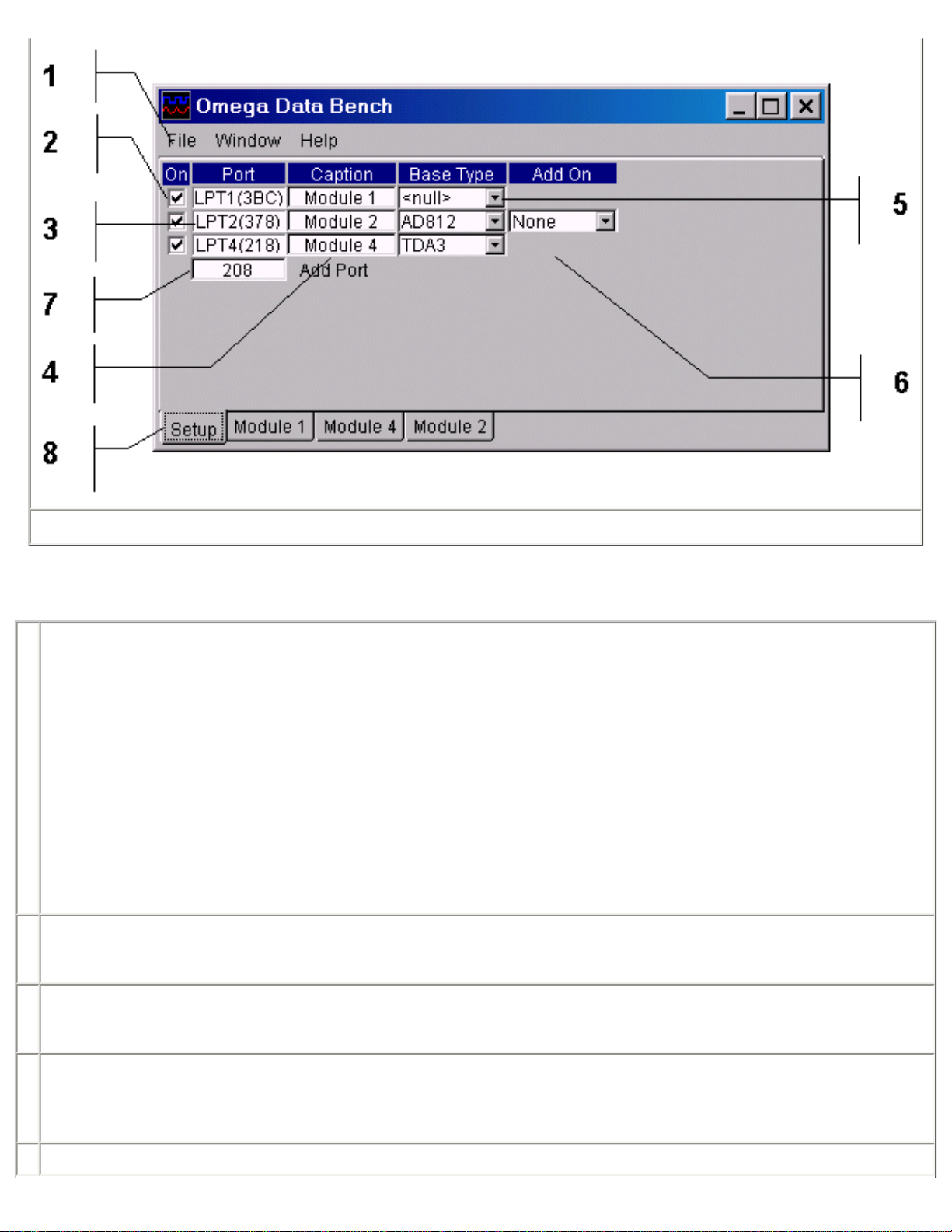
Figure 1
Referring to Figure 1 for number references; Items 2 through 7 make up a Setup Control.
1 Menu – The Menu has the following selections:
File – The File Menu has only one selection Exit. Exit closes the program.
Window – The Window Menu has two selections, Tile and Cascade. Selecting Tile will arrange the module
screens so that each is fully visible. Selecting Cascade will stack the module screens on top of each other,
showing only the Title Bars of the lower screens.
Help – The Help Menu has two selections, About and Bench Help. Selecting About will show a dialog showing the
applications Revision, Release and Copyright. The About dialog also shows statistics on the programs timing
performance. See section Performance Statistics for a more detailed discussion. Selecting Bench Help brings up
this help file.
2 The On checkbox on the Setup Panel when unchecked removes all of the modules controls and displays from the system. You can
use this to remove the controls of a module for any reason, such as when a module has been physical removed. Rechecking the
control will reinstall the module controls and displays.
3 The Port display shows the name i.e. LPT1, LPT2, etc. and the address of the ports base address in hexadecimal. The port names
for the first three ports (LPT1, LPT2 and LPT3) match the names given by the operating system. The names for ports other than
these are derived from the order you entered them. See item 8.
4 The modules Caption or name can be changes by entering a new one. The default Caption is derived from the number of the port
to which the module is attached. The modules Captions appears on the tab to the modules controls and is also pre-fixed to the titles
on all of the modules displays.
5 The Base module selection box is used to set the type of module connected directly to the printer port.
Page 5
6 The Add-on selection box is used to select the signal-conditioning module plugged into the Base module if there is one.
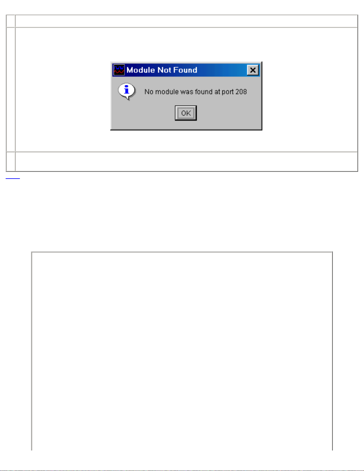
7 If non-standard printer ports have been added to the system, their base port will have to be entered (in hexadecimal) to tell Data
Bench about them. The program will then check for a module at the specified address. If a module is found, a new Setup Control
will be added. If no module is found the address field will be cleared and you will get the following message.
Once a module has been found, the program will remember to check the address for a module at the next program startup.
8 The tabs are used to select between the Setup Panel and each of the Module Control Panels. When a module is located and the
Base module type is set a new Module Control Panel tab is added.
TOC
5.0 Module Controls
A Module Control Panel is added to the panel tabs for each module installed. Figure 2 shows a typical Module Control Panel (TDA4). The
panel is made up of individual controls that are common to all modules, regardless of its type or Add-on. The following section breaks out
and describes each type of control. For details on a specific module’s controls, refer to the module's specification section. The basic
sections of the Module Control Panel are as follows:
Page 6
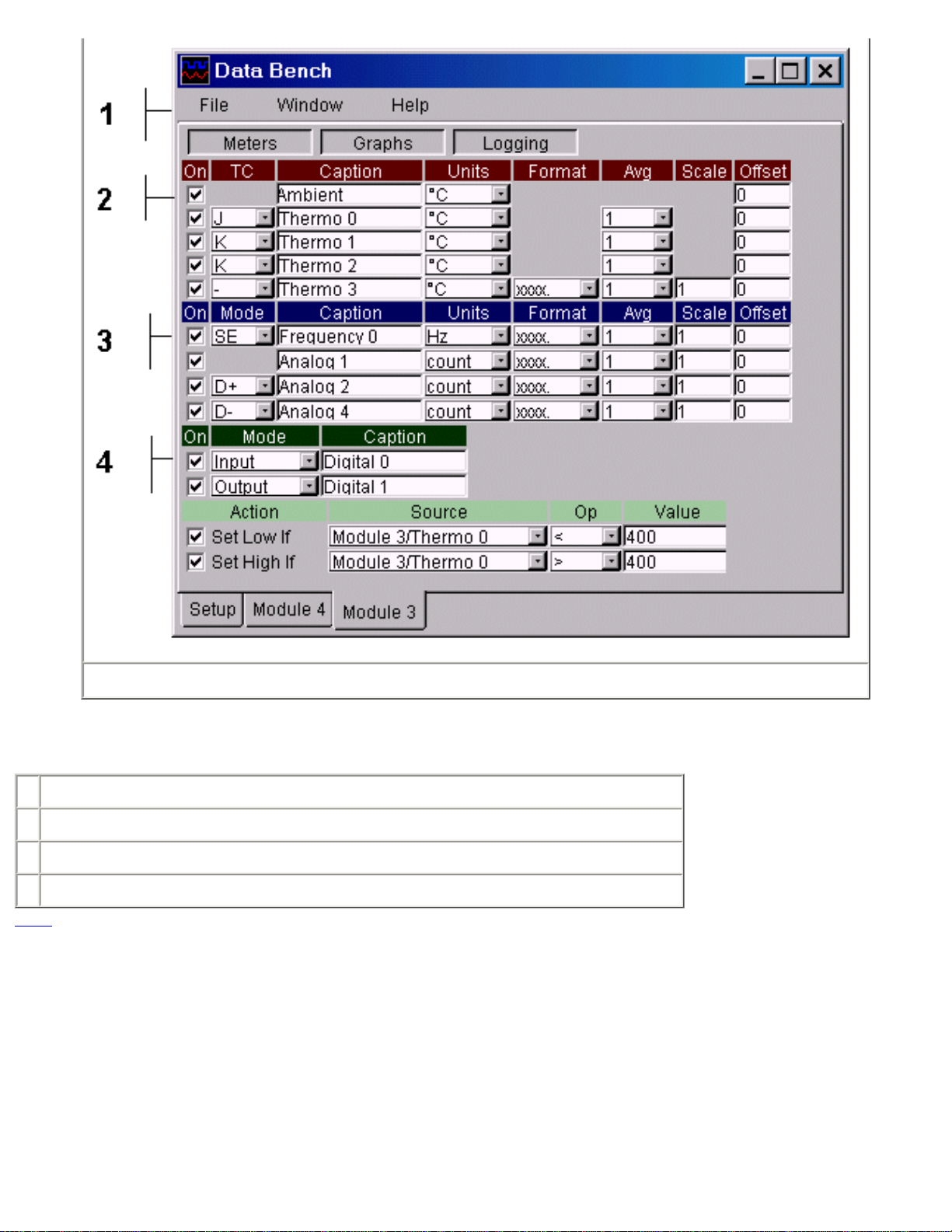
Figure 2
Refer to Figure 2 for matching numbers.
1 Display Panel Control turns Meter Panel, Graphics Panel and Logging Control Panel on or off.
2 Ambient temperature and thermocouple control section.
3 Analog control section.
4 Digital input/output control section.
TOC
5.1 Ambient Temperature and Thermocouple Input Controls
Page 7
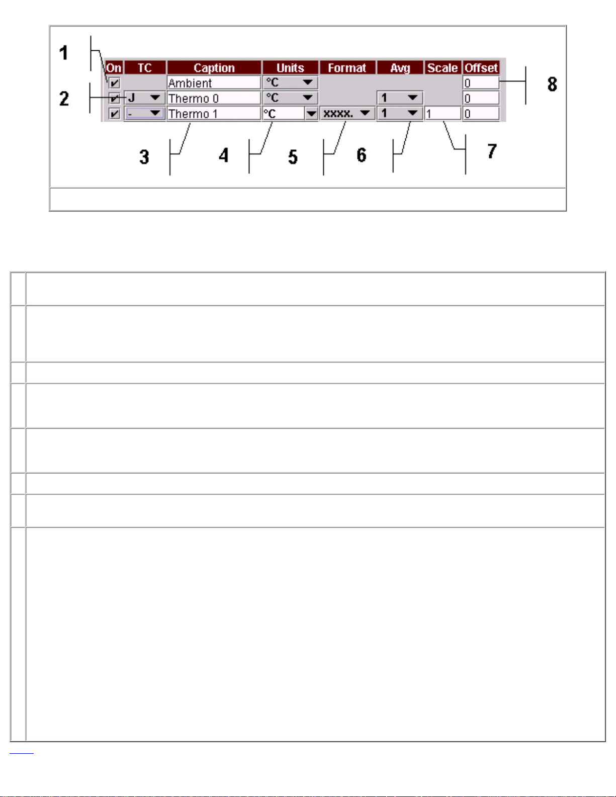
Figure 3
Ambient temperature and thermocouple input controls are added to the Module Control Panel of the TDA3, TDA4, TDA8 Base modules
and AD612 or AD812 Base modules with USC, MSC01-X or TSC5 Add-on modules. Refer to Figure 3 for matching numbers.
1 The On control when unchecked will stop data collection. Since data for the unchecked channel is not collected, it will not be
available for display on the Meter Panel, for plotting on the Plot Panel or Data Logging.
2 The TC box allows the selection of the type of thermocouple connected to the input. Type J, K and T are supported. You can also
select "-" if you want to use the input without temperature conversion. Refer to each specific module specification for detailed input
amplifier circuitry. When using the input without temperature conversion you will be able to edit the display Units; the data Format
and Scale the data input.
3 The inputs Caption or name can be changes by entering a new one. The default Caption is derived from the input type and number.
4 The Units field is used to convert the thermocouple input to temperature. If you are not using the temperature mode i.e. Type is set
to "-", you can edit the Units field as needed. The text you enter will be remembered the next time run the program only if it is
selected when the program is closed.
5 The Format selector sets the number of decimal places used when data is displayed and logged. If the data’s value exceeds the
format selection, the value "+++" or "---" will be displayed or used instead. The format selection is not available when using
temperature conversion.
6 The Avg selector sets the number of data points to average before using the value. A good choice for most applications is 20.
7 The Scale value is used scale the data value before use. The format selection is not available when using temperature conversion.
The scale factor is applied after averaging and before the offset is added. See next Item.
8 The Offset value is added to the scaled data before it is used. The order of the average, scale and offset operator is (average x
scale) + offset. This makes the offset value in "scaled" units.
The linearity of the ambient temperature sensor is very good but the absolute value can vary by ± 2 ° C. Since the thermocouple
temperatures are offset by the ambient temperature, for critical applications, you should adjust the ambient offset using one of the
following methods:
1. Use an independent reference such as thermometer.
2. Use a connected thermocouple at room temperature.
Note that the offset is in the same units as the thermocouple display units i.e. if Units (item 4) is set to ° C, the
offset will be in ° C.
TOC
Page 8
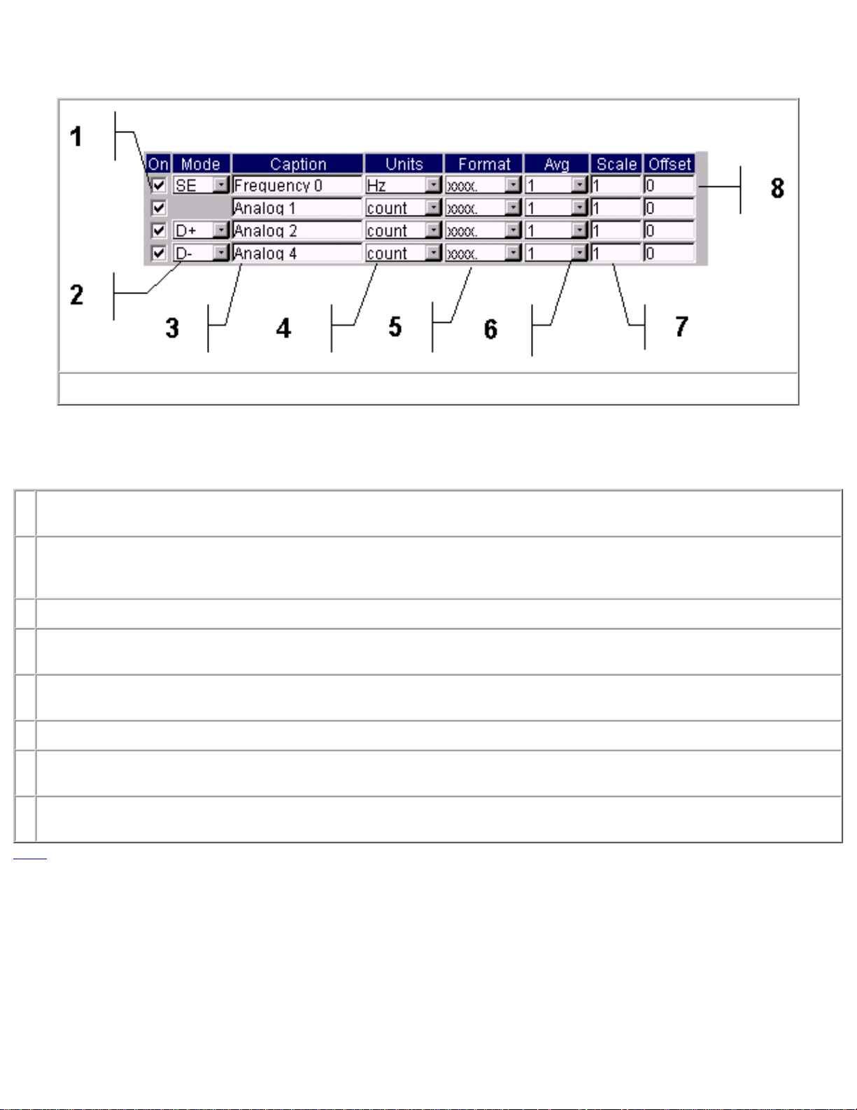
5.2 Analog Input Controls
Figure 4
Analog input Controls are added to the AD612, AD812, TDA3 and TDA4 Base modules and the AD612 or AD812 Base Module with the
USC or MSC01-X Add-on modules. Refer to Figure 4 for matching numbers.
1 The On control when unchecked will stop data collection. Since data for the unchecked channel is not collected, it will not be
available for display on the Meter Panel, for plotting on the Plot Panel or Data Logging.
2 The Mode selector sets the input mode. The available modes are SE for single ended, D+ for differential with the input with the
Mode selector being the positive input and D- for differential with the input with the Mode selector being the negative input. When
the D+ or D- modes are selected the controls for the second input are removed.
3 The inputs Caption or name can be changes by entering a new one. The default Caption is derived from the input type and number.
4 The Units field can be selected from the standard list or edited as needed. The text you enter will be remembered the next time run
the program only if it is selected when the program is closed.
5 The Format selector sets the number of decimal places used when data is displayed and logged. If the data’s value exceeds the
format selection, the value "+++" or "---" will be displayed or used instead.
6 The Avg selector sets the number of data points to average before using the value. A good choice for most applications is 20.
7 The Scale value is used scale the data value before use. The format selection is not available when using temperature conversion.
The scale factor is applied after averaging and before the offset is added. See next Item.
8 The Offset value is added to the scaled data before it is used. The order of the average, scale and offset operator is (average x
scale) + offset. This makes the offset value in "scaled" units.
TOC
5.3 Digital Input / Output Controls
Page 9
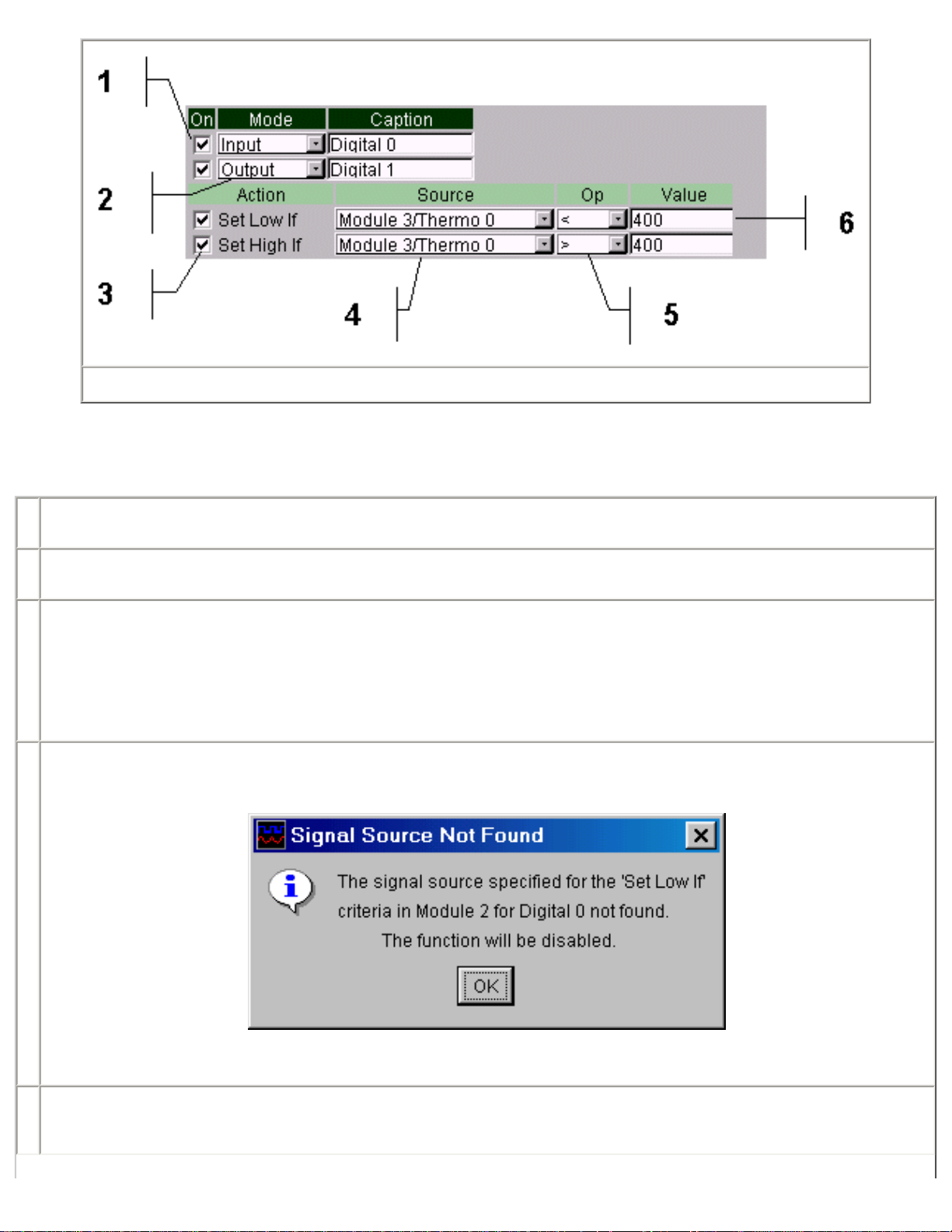
Figure 5
Digital Input / Output (I/O) Control(s) are present on all Base and Base/Add-on module combinations except the DIO16. Refer to Figure 5
for matching numbers.
1 The On control when unchecked will stop data collection. Since data for the unchecked channel is not collected, it will not be
available for display on the Meter Panel, for plotting on the Plot Panel or Data Logging.
2 The Mode selector sets the data direction of the I/O line to either an input or output. When the output mode is selected, the control
is expanded to show additional control items 3, 4, 5, and 6.
3 When the I/O line is set to output mode, the line can be set low or high under software control based on a comparison test of any
analog, thermocouple or ambient signal source present on the system. Checking the "Set Low If" box enables setting the output
line low and checking the "Set High If" box enables setting the line high. The state of the output line can also be changed from the
modules Meter Panel if the condition that set the output state no longer exists. For example, if the output line is being used to
sound an over temperature alarm when an thermocouple reading exceeds a certain value and the alarm is to be latched on, then
only one of the "Set _ If" criteria’s is used. If the alarm condition is met, the alarm is sounded but will not clear automatically when
the condition is corrected since the other "Set _ If" criteria is not active. The alarm can, however, be cleared from the Meter Panel.
4 Select the signal source to be tested. If the test is active and the signal source is removed or turned off, the following message will
be displayed.
This does not apply to renaming (changing the Caption) of a signal.
5 Select the test criteria. Care should be taken that conflicting tests are not set when using both the "Set Low If" and Set High If"
functions. For example, "Set Low If" signal x = 400 and "Set High If" signal x = 400 have a conflict. Care should also be taken when
using the "=" test criteria as rapidly varying signal may never actually match.
Page 10
6 Enter the test criteria value.
TOC
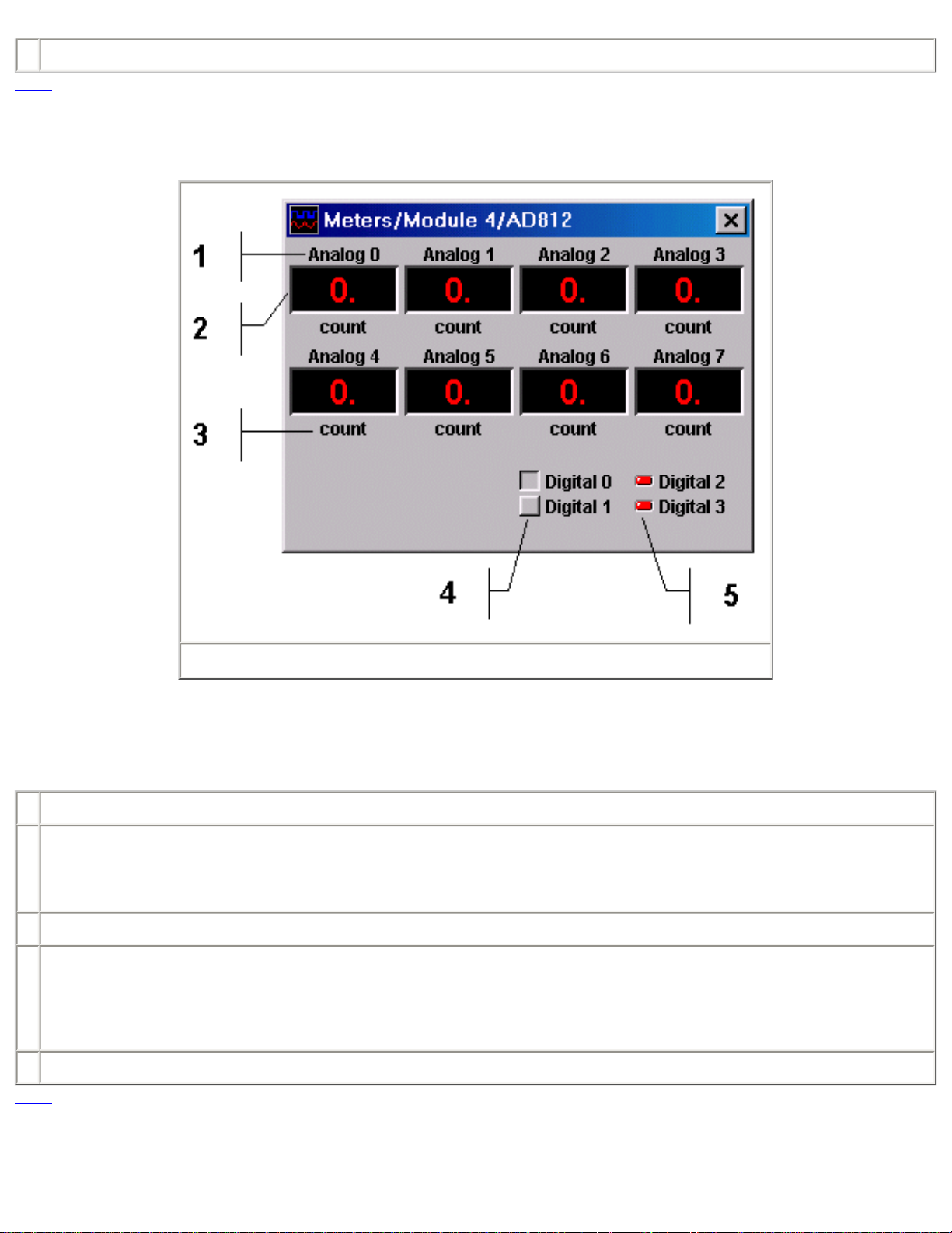
6.0 Meter Panels
Figure 7
A Meter Panel is created for each module. The Meter Panel is identified in the title bar with the modules Caption from the modules Setup
Control and the modules Base and Add-on type. The Meter Panel display may be turned on or off with the Display Control at the top of
the Module Panel. Refer to Figure 7 for matching numbers.
1 The individual meter displays have a Caption. The Caption is set from the Module Control Panel.
2 The Individual meters display the latest value of the input. The display has 4 digits and a decimal point. The format for the display is
set from the Module Control Panel. If the value to be displayed exceeds the format specified, "+++" is displayed if the value is
greater than the largest value that can be displayed and "---" if the value is less than the minimum value that can be displayed. For
example, if the format is set to "X.XXX" and the number 10.000 is attempted to be displayed, the result will be "+++".
3 The Units represented by the meter display is shown under the meter.
4 Digital I/O lines set in the output mode have associated toggle buttons. A low state set and indicated by the button being raised and
a high state by the button being inset. When the lines "Set _ If" functions are used, the state of the buttons will change based on the
evaluation of the function. Attempts to manually override the state set by the function will simply be changed to the state resulting
from the function evaluation. For example, if the "Set High If" function has set the line high and the line is then manually set low, the
function will simply set the line back to the high state provided it still evaluates to high.
5 Digital I/O lines used as inputs have their state displayed by LED type indicators.
TOC
7.0 Plot Panel
Page 11
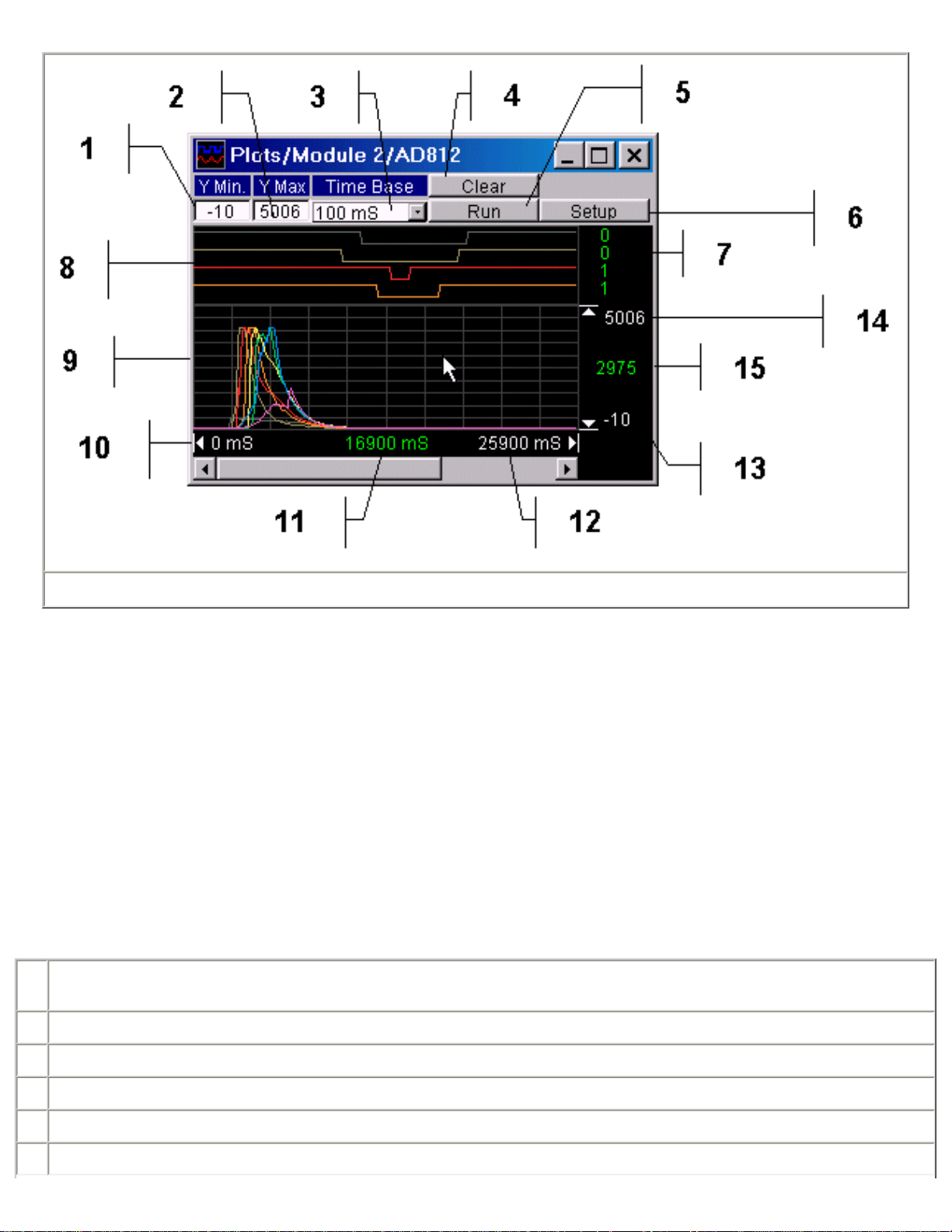
Figure 8
A Plot Panel is created for each module. The Meter Panel is identified in the title bar with the modules Caption from the modules Setup
Control and the modules Base and Add-on type. The Plot Panel display may be turned on or off with the Display Control at the top of the
Module Panel.
The Plot Panel provides a rudimentary method for viewing data as it is collected. The range (Y-axis) is set using the minimum and
maximum values to be plotted. Both the minimum and maximum plot values can be changed dynamically to zoom in or out. The time
scale (X-axis), however, can not be changed dynamically and changing the time base selection will restart plotting.
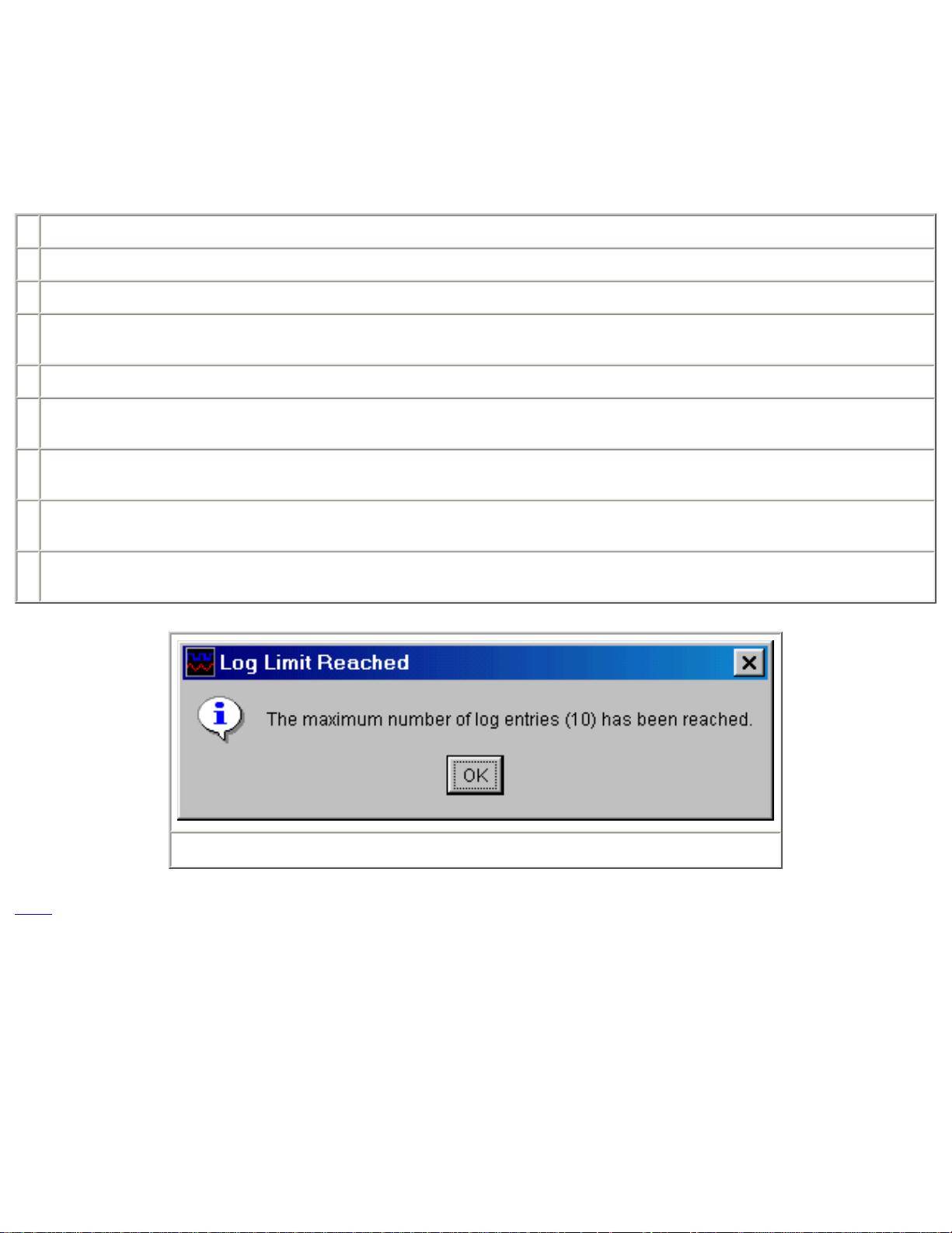
The maximum number of points that can be plotted is 8192. When the number of points plotted reaches this limit, the message in Figure
12 is displayed and the plot must be cleared to continue plotting.
The graph is divided into a digital and an analog section. Both sections use the same time base but the digital section is not scalable.
Refer to Figure 8 for matching numbers.
1 Enter the minimum analog value to be plotted. This number must always be less than the maximum analog value (Item 2) and the
program will swap the two values to force this condition.
2 Enter the Maximum analog value to be plotted.
3 Select the plot time base. Changing this selection will cause the plot to restart.
4 The Clear button restarts plotting. The plot can be running when cleared.
5 The Run toggle button starts or stops plotting.
6 The Setup button activates the setup panel. See Figure 10 for details.
Page 12
7 When the cursor is in a plotted area, the binary values of the digital line are shown.
8 The digital plot area shows the states of the digital lines. This area is not affected by the Y Scale settings. The X axis scale is set
by the Interval selector.
9 The analog plot area shows plots of analog signals. The Y axis range is set from Y Min and Y Max. The Y Min and Y Max value
can be changed while collecting data without any loss of data. The X axis scale is set by the Interval selector.
10 Shows the graph start time.
11 Shows the cursor time value.
12 Shows the graph end time.
13 Shows Y Min.
14 Shows Y Max.
15 Shows the cursor y value.
Figure 9
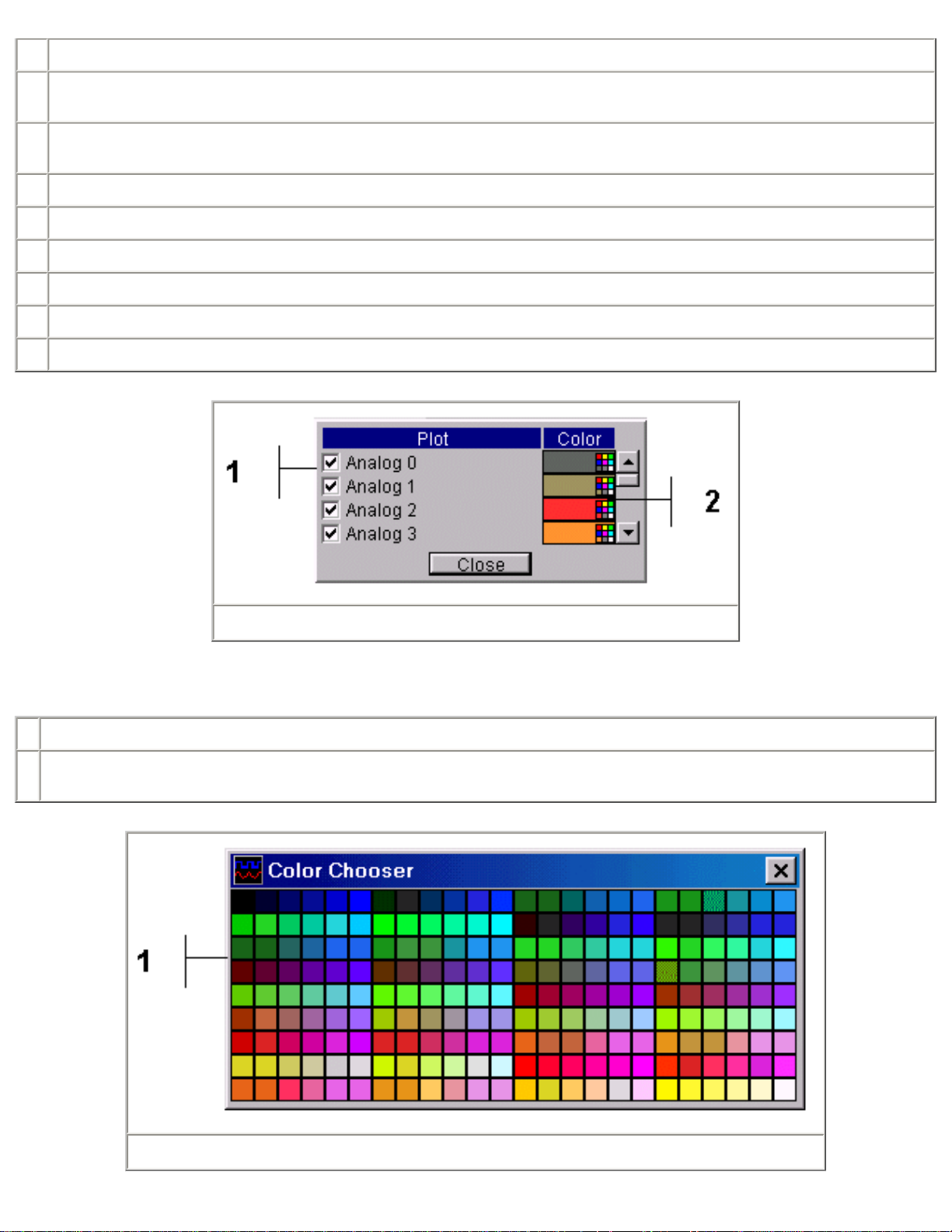
The Plot Setup Panel, Figure 9, allows signals to be turned on or off and the trace colors to be changed.
1 A check box controls for each signal, turns plotting on or off.
2 A color selector for each signal allows trace color selection. Clicking the traces color selector activate the Color Chooser Panel. See
Figure 11.
Figure 10
Page 13
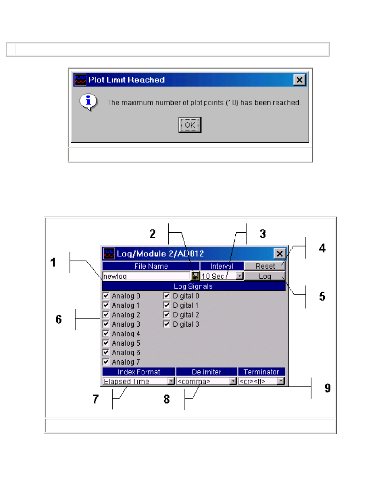
The Color Chooser Panel, Figure 10, is used to set the color of a signal trace.
1 Click any color box to select that color and close the dialog or close the using the Close button to make no change.
Figure 11
TOC
8.0 Logging Configuration Panel
Figure 12
The Logging Configuration Panel is used to setup a file to which data is saved, specify the interval at which the data is saved, which
signals are saved and the format of the data file entries. Each time the log interval is reached plain text line representing the data to be
saved is written to the specified file. The format of the saved data consists of an index entry followed by an entry for each of the data
Page 14
signals selected. A delimiter character separates each entry and the line is terminated with a terminator character. The lines format is
"IndexEntry<delimiter>FirstDataEntry<delimiter>...<delimiter>LastDataEntry<terminator>".
The maximum number of log entries is 8192. When the number of entries reaches this limit, the message in Figure 13 is displayed and
the log file must be Reset or a new file opened to continue plotting.
Refer to Figure 12 for matching numbers.
1 Enter the name of the file where the data is to be saved. Include the path as necessary.
2 Activates the File Open Panel. This is a familiar file selection dialog that is used to select a file instead of typing in the file name.
3 Select the time interval at which the data is to be saved.
4 The Reset button causes the data logging to restart at the beginning of the file. This can be done before or during logging. By
default data is appended to an existing file unless the Reset is pressed.
5 The Log toggle button starts and stops logging.
6 One check box for each signal available on the module allows selection data to be saved. If the data signal is disabled on the
module control panel, the check box will be disabled.
7 Select the index entry for the logged data. The options are Index, a running count of the entries; Elapsed Time, the time in ms since
the program started; System Time, the time of day in hrs:min:sec; and System Date/Time, the date and time of day.
8 Select the delimiter character to be used between each entry in the line. The options are tab, space, comma (,), semi-colon (;) or
colon (:).
9 Select the termination character to be added to the end of each line. The options are Carriage Return; Line Feed or Carriage
Return and Line Feed.
Figure 13
TOC
9.0 Performance Statistics
Page 15
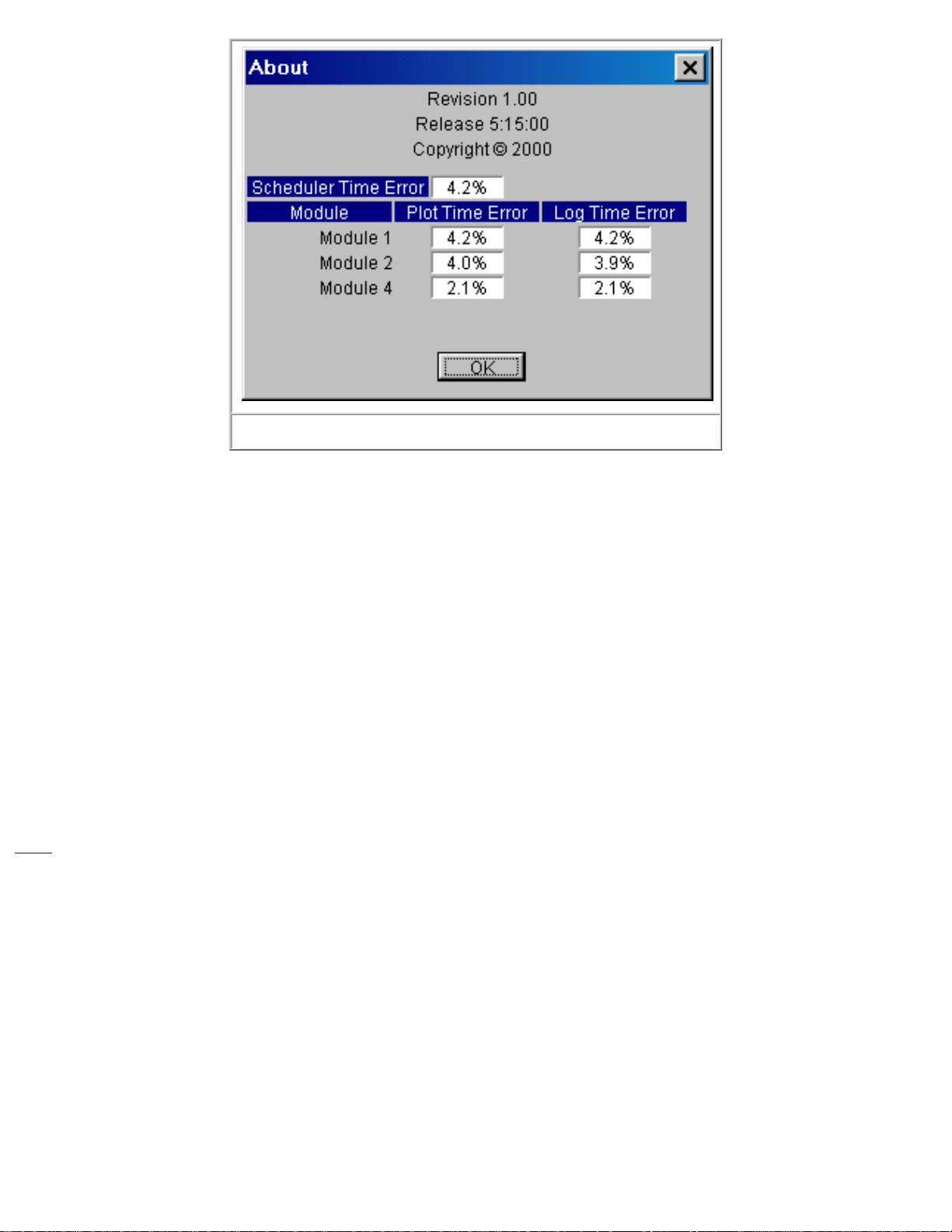
Figure 14
The About Panel shown in Figure 14 displays statistics about the programs internal operations. As with all programs that rely on operating
systems resources, the program's performance depends on the systems resource loading. At the heart of the program is a task scheduler
that uses a system timer that runs at the highest priority. Every 20 ms the task timer checks to see if any tasks i.e. data conversions, data
plotting or data logging are running. If no tasks are running the scheduler will start the execution of all the tasks required. If previously
scheduled tasks are still running, the scheduler waits 1 ms and checks for task completion again. This 1 mS check continues until all
previously scheduled tasks have executed and a new set of tasks are scheduled. The Scheduler Time Error shows the percent time error
of the scheduler. In the case shown in Figure 14, there are three modules running each of which are plotting and logging data. Module 1
is plotting and logging every 20 ms, Module 2 every 40 ms and Module 4 every 100 mS. As can be seen from Figure 14, the average
scheduling error is 4.2% or .84 mS.
Both the Plot and Log functions have individually set Intervals that are multiples of the task scheduler period of 20 mS. Figure 14, shows
the plot and log time errors for each module. Since Module 1 has an interval of 20 ms, its errors are identical to the scheduler error.
Module 2 has an interval of 40 ms and has a 4.0% error for the plot function and a 3.9% error for the logging function. In time these errors
are 1.6 ms and 1.56 mS. Module 4 has an interval of 100 ms and a 2.1% (2.1 ms) error for both the plot and logging functions.
The time errors will change depending on the speed of the computer, what functions are running and what other applications are running.
If the time errors are unacceptable for a given use, try shutting down other applications and reducing the running functions.
TOC
10.0 Related Files
The application maintains a set of initialization files for the application and each printer port on which a module has been installed. These
files are located in the \bin directory where the application resides. The applications initialization file is named bench.box and the
individual module initialization files are saved as modulex.box where the x is the port number i.e. initialization data for the module
connected to LPT1 is stored in module1.box, etc.
If any of these initialization files should become corrupted simply delete them and the application will build new ones.
There are two lines in the bench.box that can be manually edited. These lines set the maximum number of plot points and the maximum
number of log entries. The lines are always the last two in the file and are originally as follows:
Maximum Plot Points=8192
Page 16
Maximum Log Entries=8192
Change only the number to the desired value and save the file. The change will take affect the next time the application is run.
TOC
11.0 Data Sheets
Product Specification Omega Engineering, Inc.
Model OMK-AD612
6 Channel Analog Data Acquisition Module with 12 Bit
Resolution
General Description
The OMK-AD612 analog data acquisition module has six analog inputs with twelve-bit resolution. The inputs can be used single ended or
in pairs differentially. An internal reference voltage of 4.096V ± .2%, yields a conversion of 1mV / LSB.
The module is hosted and powered by a PC compatible printer port and no external power supply is required. The Module is compatible
with SPP, BPP, EPP and ECP type printer ports.
The module passes though four bi-directional digital input/output ports from the host printer port. The digital I/O lines can be set or
cleared based on the analog inputs with the bundled software.
Features
6 Single Ended or 3 Differential Inputs.
•
12 Bit Resolution, 1mV / LSB.
•
0 to 4.096V Input Range.
•
4 Digital I/O Lines.
•
Printer Port Connected and Powered.
•
Page 17
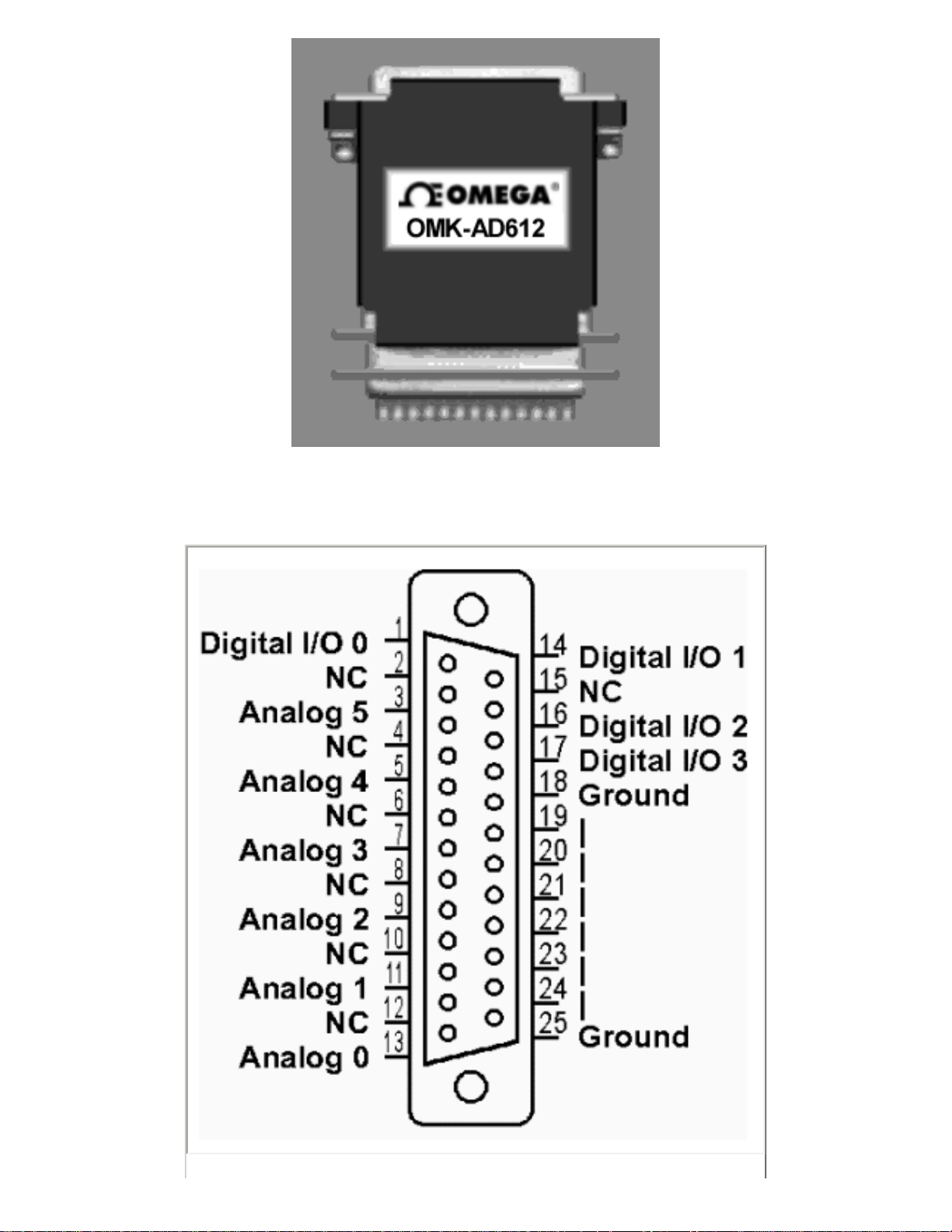
Pin Configuration
Page 18
Specifications
Signal Pin #
Analog 0 13
Analog 1 11
Analog 2 9
Analog 3 7
Analog 4 5
Analog 5 3
Digital I/O 0 1
Digital I/O 1 14
Digital I/O 2 16
Digital I/O 3 17
Ground 18-25
Analog Inputs
Analog channels 6
Resolution 12 Bits
Analog input range 4.096 V
Analog Input Resistance
Offset Error
Linearity Error
Gain Error
Over-voltage Protection
Digital I/O
Digital I/O lines 4
Max. current (sinking) 4 mA
10 kΩ
± 3 LSB
± 0.5 LSB
± 1.0 LSB
± 15 VDC
Max. current (sourcing) 0.5 mA
Over-voltage protection
Physical
± 5V
Page 19

Operating temp. range
Power consumption 50 mW
0 to 70 ° C
Conversion Time
With bundled software 20 mS
Application Information
Analog Inputs
The analog inputs can be configured for single ended input or in odd/even pairs for differential input. Table 1 shows the possible
differential configurations. Any combination of single ended and differential configurations may be used. When using the inputs in
differential mode, only the designated plus (+) input supports the sample/hold feature. Therefore, changes in the minus (-) input during
sampling may cause a conversion accuracy error. The input frequency and amplitude on the minus input should be limited to reduce
errors. For an error of 0.25 LSB, the maximum sinusoid input, at 4V-peak amplitude, should be less than 1Hz.
All unused inputs should grounded.
Mode Input Function
D+ Analog0 Differential +
Digital I/O Lines
D- Analog0 Differential -
D+ Analog2 Differential +
D- Analog2 Differential -
D+ Analog4 Differential +
D- Analog4 Differential -
Analog1 Differential -
Analog1 Differential +
Analog3 Differential -
Analog3 Differential +
Analog5 Differential -
Analog5 Differential +
Table 1
The Digital I/O lines are inherited from the printer port implementation. Figure 1 shows a typical circuit for the Digital I/O lines. The output
is driven by an open collector inverter and as the input is a standard inverter. If the output is set low, the input can not be pulled high and
is therefore not usable. Not all printer ports fully support the input function while all do support the output function. Multi-mode (ECP)
printer ports may support the input function in some modes (SPP, BPP) but not in other modes. If the input function is needed but does
Page 20
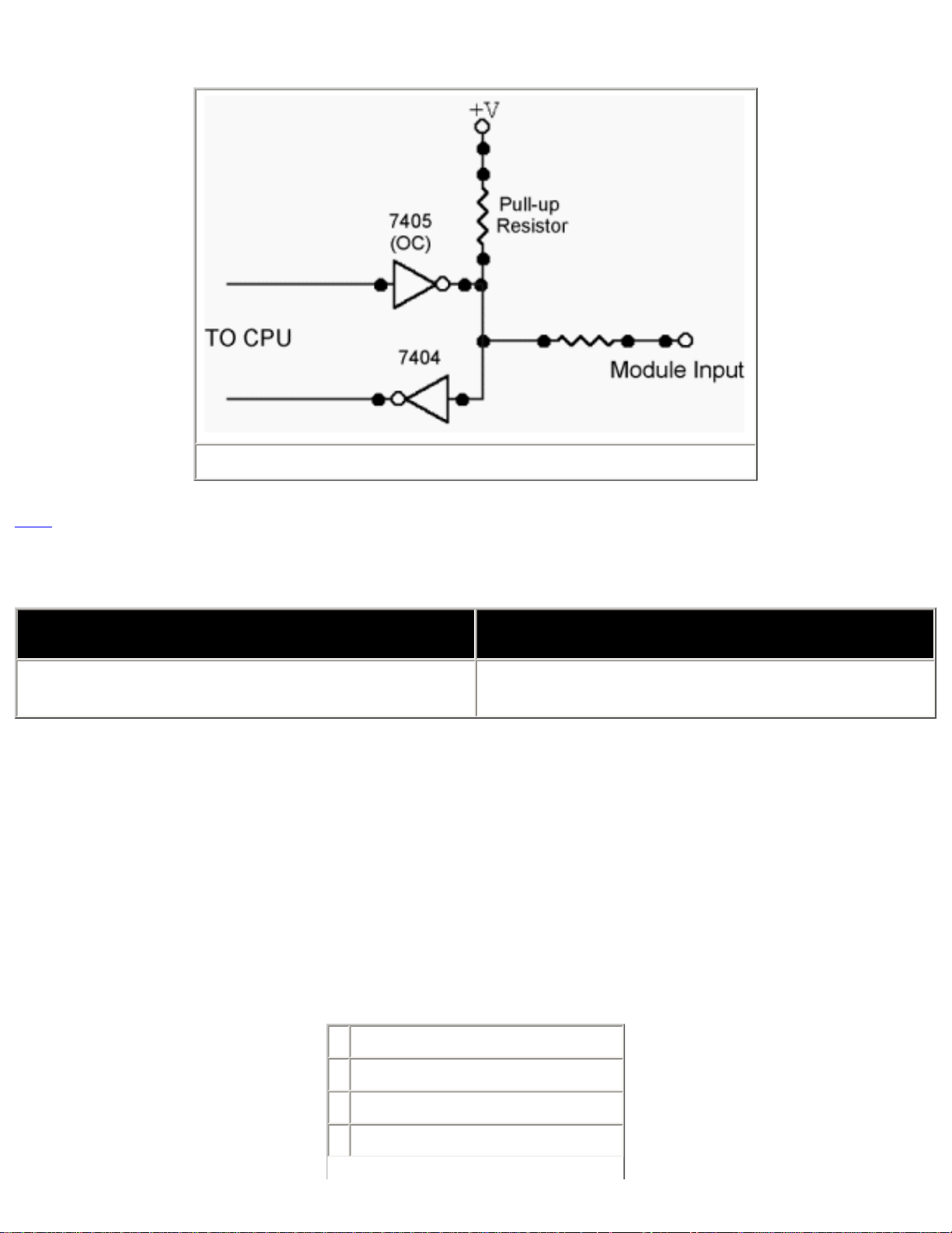
not function, change the printer ports mode form the BIOS setup.
Figure 1
TOC
Product Specification Omega Engineering, Inc.
Model OMK-AD812
General Description
The OMK-AD812 analog data acquisition module has eight analog inputs with twelve-bit resolution. The inputs can be used single ended
or in pairs differentially. An internal reference voltage of 4.096V ± .2%, yields a conversion of 1mV / LSB.
The module is hosted and powered by a PC compatible printer port and no external power supply is required. The Module is compatible
with SPP, BPP, EPP and ECP type printer ports.
The module passes though four bi-directional digital input/output ports from the host printer port. The digital I/O lines can be set or
cleared based on the analog inputs with the bundled software.
8 Channel Analog Data Acquisition Module with 12 Bit
Resolution
Features
8 Single Ended or 4 Differential Inputs.
•
12 Bit Resolution, 1mV / LSB.
•
0 to 4.096V Input Range.
•
4 Digital I/O Lines.
•
Page 21
Printer Port Connected and Powered.
•
Pin Configuration
Page 22
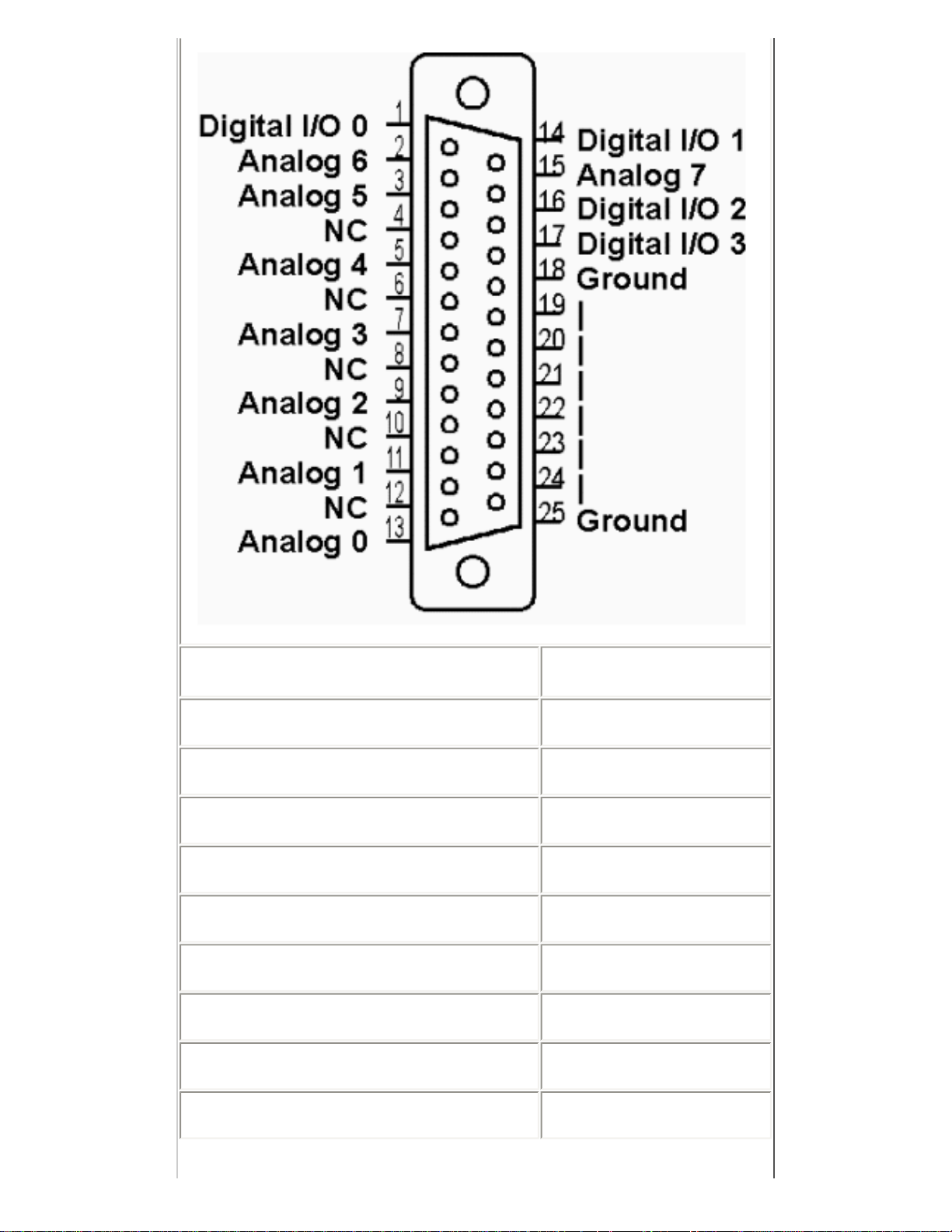
Signal Pin #
Analog 0 13
Analog 1 11
Analog 2 9
Analog 3 7
Analog 4 5
Analog 5 3
Analog 6 2
Analog 7 15
Digital I/O 0 1
Page 23
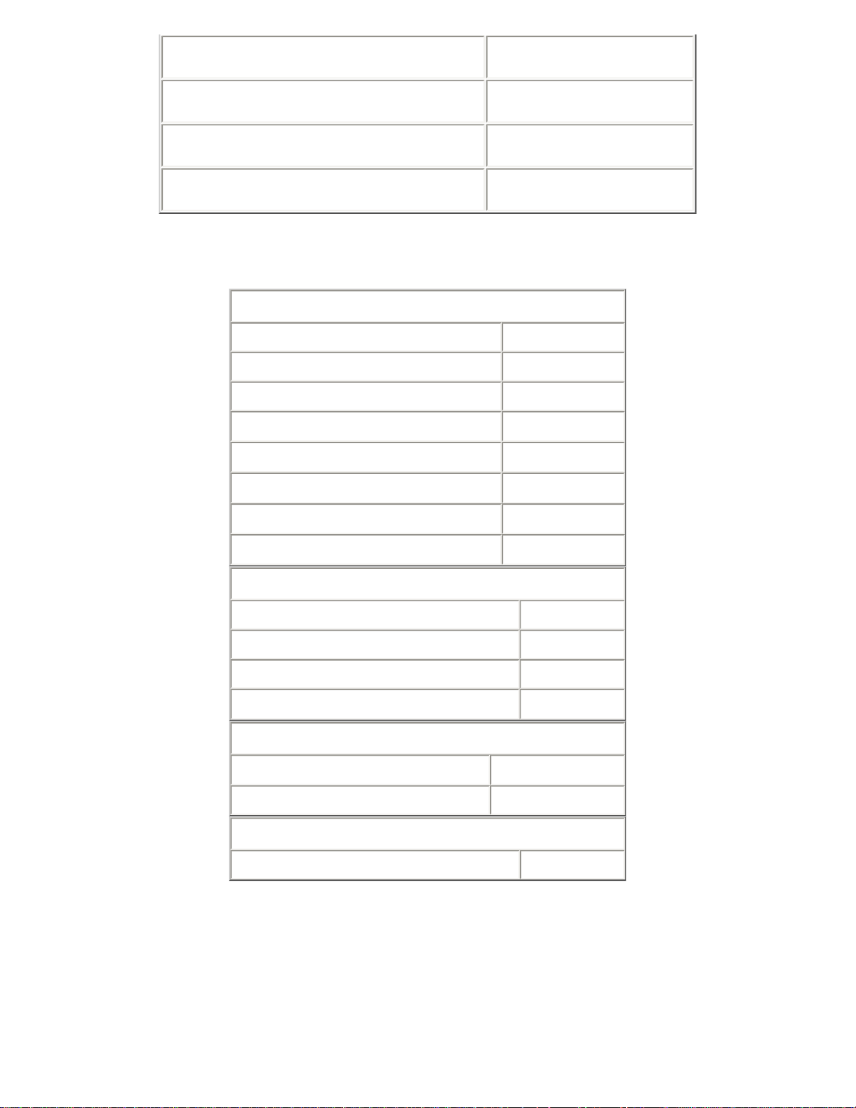
Specifications
Digital I/O 1 14
Digital I/O 2 16
Digital I/O 3 17
Ground 18-25
Analog Inputs
Analog channels 8
Resolution 12 Bits
Analog input range 4.096 V
Analog Input Resistance
Offset Error
Linearity Error
Gain Error
Over-voltage Protection
10 kΩ
± 3 LSB
± 0.5 LSB
± 1.0 LSB
± 15 VDC
Digital I/O
Digital I/O lines 4
Max. current (sinking) 4 mA
Max. current (sourcing) 0.5 mA
Over-voltage protection
± 5V
Physical
Operating temp. range
Power consumption 50 mW
0 to 70 ° C
Conversion Time
with bundled software 20 mS
Application Information
Analog Inputs
The analog inputs can be configured for single ended input or in odd/even pairs for differential input. Table 1 shows the possible
differential configurations. Any combination of single ended and differential configurations may be used. When using the inputs in
differential mode, only the designated plus (+) input supports the sample/hold feature. Therefore, changes in the minus (-) input during
Page 24

sampling may cause a conversion accuracy error. The input frequency and amplitude on the minus input should be limited to reduce
errors. For an error of 0.25 LSB, the maximum sinusoid input, at 4V-peak amplitude, should be less than 1Hz.
All unused inputs should grounded.
Mode Input Function
D+ Analog0 Differential +
D- Analog0 Differential -
D+ Analog2 Differential +
D- Analog2 Differential -
D+ Analog4 Differential +
D- Analog4 Differential -
D+ Analog6 Differential +
D- Analog6 Differential -
Analog1 Differential -
Analog1 Differential +
Analog3 Differential -
Analog3 Differential +
Analog5 Differential -
Analog5 Differential +
Analog7 Differential -
Analog7 Differential +
Table 1
Digital I/O Lines
The Digital I/O lines are inherited from the printer port implementation. Figure 1 shows a typical circuit for the Digital I/O lines. The output
is driven by an open collector inverter and as the input is a standard inverter. If the output is set low, the input can not be pulled high and
is therefore not usable. Not all printer ports fully support the input function while all do support the output function. Multi-mode (ECP)
printer ports may support the input function in some modes (SPP, BPP) but not in other modes. If the input function is needed but does
not function, change the printer ports mode form the BIOS setup.
Page 25

TOC
Figure 1
Product Specification Omega Engineering, Inc.
Model OMK-PG812
8 Channel Analog Data Acquisition Module with 11/12
Bit Resolution and Programable Gain
General Description
The OMK-PG812 analog data acquisition module has eight analog inputs with eleven-bit resolution in single ended mode and twelve-bit
resolution in differential mode. The inputs when used differentially in pairs have an input range of 0 to 5 volts making the module ideal for
interfacing to bridge type devices directly. The gain of each channel or differential pair is programable to gains of 1,2,4,5,8,10,16 or 20.
The internal reference voltage can be set to 2.048 or 2.500 volts. In single ended mode, the 2.048 volt reference yields a conversion of
1mV / LSB.
The module is hosted and powered by a PC compatible printer port and no external power supply is required. The Module is compatible
with SPP, BPP, EPP and ECP type printer ports.
The module has four bi-directional digital input/output ports that can be set or cleared based on the analog inputs with the bundled
software.
Features
8 Single Ended or 4 Differential Inputs.
•
11 Bit Resolution Single Ended.
•
12 Bit Resolution Differential.
•
Programable Gains of 1,2,4,5,8,10,16 or 20
•
2.048 or 2.500 Volts Full Scale.
•
Page 26

4 Digital I/O Lines.
•
Printer Port Connected and Powered.
•
Pin Configuration
Page 27

Signal Pin #
Analog 0 12
Analog 1 11
Analog 2 10
Analog 3 9
Analog 4 8
Analog 5 7
Analog 6 6
Analog 7 5
Page 28

Specifications
Digital I/O 0 4
Digital I/O 1 3
Digital I/O 2 2
Digital I/O 3 1
Ground 19-24
Note: Make no connections to pins marked NC.
Analog Inputs
Analog channels 8
Resolution (Single Ended) 11 Bits
Resolution (Differential) 12 Bits
Analog input gain 1,2,4,5,8,10,16 or 20
Analog input range 2.048 or 2.500 V
Analog Input Resistance
Offset Error
Linearity Error
Gain Error
Over-voltage Protection
10 kΩ
± 3 LSB
± 0.5 LSB
± 1.0 LSB
± 15 VDC
Digital I/O
Digital I/O lines 4
Max. current (sinking) 4 mA
Max. current (sourcing) 0.5 mA
Over-voltage protection
± 5V
Physical
Operating temp. range
0 to 70 ° C
Application Information
Power consumption 50 mW
Conversion Time
with bundled software 20 mS
Page 29

Analog Inputs
The analog inputs can be configured for single ended input or in odd/even pairs for differential input. Table 1 shows the possible
differential configurations. Any combination of single ended and differential configurations may be used. In single ended mode, the input
voltage range is 0 to vref/gain. For example, with vref set to 2.048 volts and gain set to 20 to single ended input voltage range is 0 to
102.4 mV. In differential mode, the input voltage range spans both the positive and negative so that using the previous example, the
differential input voltage range is -102.4 to 102.4 volts. The absolute input voltage in differential mode can be between 0 and 5 volts.
All unused inputs should grounded.
Mode Input Function
D+ Analog0 Differential +
D- Analog0 Differential -
D+ Analog2 Differential +
D- Analog2 Differential -
D+ Analog4 Differential +
D- Analog4 Differential -
D+ Analog6 Differential +
D- Analog6 Differential -
Analog1 Differential -
Analog1 Differential +
Analog3 Differential -
Analog3 Differential +
Analog5 Differential -
Analog5 Differential +
Analog7 Differential -
Analog7 Differential +
Table 1
Digital I/O Lines
Figure 1 shows a typical circuit for the Digital I/O lines. The output is driven by an tri-state buffer and as the input is a standard buffer. The
10K pull-up resistor makes interface inputs with simple closures to ground easy and the 33 ohm resistor provides impedance matching to
standard cables.
Page 30

TOC
Figure 1
Product Specification Omega Engineering, Inc.
Model OMK-TDA3
3 Channel Thermocouple / 2 Channel Analog Data
Acquisition Module with 12 Bit Resolution
General Description
The OMK-TDA3 thermocouple and analog data acquisition module has three thermocouple and two analog inputs with twelve bit
resolution.
The thermocouple inputs can be used with type J, K, or T thermocouples in any combination. The module provides an ambient
temperature sensor for cold junction correction. Temperature conversion with the bundled software is ± 1 ° C with .1 ° C resolution.
The analog inputs can be used single ended or in pairs differentially. An internal reference voltage of 4.096V ± .2%, yields a conversion
resolution of 1mV / LSB.
The module is hosted and powered by a PC compatible printer port and no external power supply is required. The Module is compatible
with SPP, BPP, EPP and ECP type printer ports.
The module passes though four bi-directional digital input/output ports from the host printer port. The digital I/O lines can be set or
cleared based on the analog inputs with the bundled software.
Page 31

Features
3 Thermocouple Inputs for J,K or T Types
•
• ± 1 ° C Accuracy with .1 ° C Resolution.
Differential Input –6.5 to 65.5 mV
•
Built in Ambient Cold Junction Correction
•
2 Single Ended or 1 Differential Input.
•
12 Bit Resolution, 1mV / LSB.
•
0 to 4.096V Input Range.
•
4 Digital I/O Lines.
•
Printer Port Connected and Powered.
•
Pin Configuration
Page 32

Signal Pin #
Thermocouple 0+ 6
Thermocouple 0- 7
Thermocouple 1+ 4
Thermocouple 1- 5
Thermocouple 2+ 2
Thermocouple 2- 3
Analog 0 12
Analog 1 11
Digital I/O 0 1
Digital I/O 1 14
Digital I/O 2 0 16
Digital I/O 3 17
Specifications
Ground 18-25
Thermocouple Inputs
Page 33

Thermocouple channels 3
Thermocouple ranges:
Thermocouple accuracy
-50 ° C to 800 ° C
J
-50 ° C to 1000 ° C
K
-25 ° C to 500 ° C
T
± 1 ° C
Analog Inputs
Analog channels 2
Resolution 12 Bits
Analog input range 4.096 V
Analog Input Resistance
Offset Error
Linearity Error
Gain Error
10 kΩ
± 3 LSB
± 0.5 LSB
± 1.0 LSB
Application Information
Over-voltage Protection
± 15 VDC
Digital I/O
Digital I/O lines 4
Max. current (sinking) 4 mA
Max. current (sourcing) 0.5 mA
Over-voltage protection
Physical
Operating temp. range
Power consumption 50 mW
± 5V
0 to 70 ° C
Conversion Time
With bundled software 20 mS
Thermocouple Inputs
The thermocouple inputs can each be connected to a J, K or T type thermocouple. Table 1 lists the color coding for each type. The
ambient temperature sensor is used by the bundled software to provide cold junction temperature correction. For critical application a
software correction ambient temperature reading may be required.
The inputs can also be used without temperature conversion as a high gain differential input. The circuitry is shown in Figure 1. When
used as a differential input, both inputs should be in the range of 0 to 5V. The output is biased to +. 5V with no input and the dynamic
input range is –6.5 mV to 46.5 mV.
Page 34

Type Minus Wire Plus Wire
J Red Insulation White Insulation
K Red Insulation Yellow Insulation
T Red Insulation Blue Insulation
Table 1
Figure 1
Analog Inputs
The analog inputs can be configured for single ended input or in odd/even pairs for differential input. Table 2 shows the possible
differential configurations. Any combination of single ended and differential configurations may be used. When using the inputs in
differential mode, only the designated plus (+) input supports the sample/hold feature. Therefore, changes in the minus (-) input during
sampling may cause a conversion accuracy error. The input frequency and amplitude on the minus input should be limited to reduce
errors. For an error of 0.25 LSB, the maximum sinusoid input, at 4V-peak amplitude, should be less than 1Hz.
All unused inputs should grounded.
Mode Input Function
D+ Analog0 Differential +
D- Analog0 Differential -
Analog1 Differential -
Analog1 Differential +
Table 2
Digital I/O Lines
The Digital I/O lines are inherited from the printer port implementation. Figure 2 shows a typical circuit for the Digital I/O lines. The output
is driven by an open collector inverter and as the input is a standard inverter. If the output is set low, the input can not be pulled high and
is therefore not usable. Not all printer ports fully support the input function while all do support the output function. Multi-mode (ECP)
printer ports may support the input function in some modes (SPP, BPP) but not in other modes. If the input function is needed but does
Page 35

not function, change the printer ports mode form the BIOS setup.
Figure 2
TOC
Product Specification Omega Engineering, Inc.
Model OMK-TDA4
General Description
The OMK-TDA4 thermocouple and analog data acquisition module has four thermocouple and six analog inputs with twelve bit resolution.
The thermocouple inputs can be used with type J, K, or T thermocouples in any combination. The module provides an ambient
temperature sensor for cold junction correction. Temperature conversion with the bundled software is ± 1 ° C with .1 ° C resolution.
The analog inputs can be used single ended or in pairs differentially. An internal reference voltage of 4.096V ± .2%, yields a conversion
resolution of 1mV / LSB.
The module is hosted and powered by a PC compatible printer port and no external power supply is required. The Module is compatible
with SPP, BPP, EPP and ECP type printer ports.
4 Channel Thermocouple / 6 Channel Analog Data
Acquisition Module with 12 Bit Resolution
The module passes though two bi-directional digital input/output ports from the host printer port. The digital I/O lines can be set or cleared
based on the analog inputs with the bundled software.
Features
Page 36

4 Thermocouple Inputs for J,K or T Types
•
• ± 1 ° C Accuracy with .1 ° C Resolution.
Differential Input –6.5 to 65.5 mV
•
Built in Ambient Cold Junction Correction
•
6 Single Ended or 3 Differential Inputs.
•
12 Bit Resolution, 1mV / LSB.
•
0 to 4.096V Input Range.
•
2 Digital I/O Lines.
•
Printer Port Connected and Powered.
•
Pin Configuration
Page 37

Signal Pin #
Thermocouple 0+ 10
Thermocouple 0- 22
Thermocouple 1+ 11
Thermocouple 1- 23
Thermocouple 2+ 12
Thermocouple 2- 24
Thermocouple 3+ 13
Thermocouple 3- 25
Analog 0 9
Analog 1 8
Page 38

Analog 2 7
Analog 3 6
Analog 4 5
Analog 5 4
Digital I/O 0 2
Digital I/O 1 1
Ground 14-21
Specifications
Thermocouple Inputs
Thermocouple channels 4
Thermocouple ranges:
Thermocouple accuracy
-50 ° C to 800 ° C
J
-50 ° C to 1000 ° C
K
-25 ° C to 500 ° C
T
± 1 ° C
Analog Inputs
Analog channels 6
Resolution 12 Bits
Analog input range 4.096 V
Analog Input Resistance
Offset Error
Linearity Error
Gain Error
10 kΩ
± 3 LSB
± 0.5 LSB
± 1.0 LSB
Over-voltage Protection
± 15 VDC
Digital I/O
Digital I/O lines 2
Max. current (sinking) 4 mA
Max. current (sourcing) 0.5 mA
Over-voltage protection
± 5V
Physical
Operating temp. range
0 to 70 ° C
Page 39

Power consumption 50 mW
Conversion Time
With bundled software 20 mS
Application Information
Thermocouple Inputs
The thermocouple inputs can each be connected to a J, K or T type thermocouple. Table 1 lists the color coding for each type. The
ambient temperature sensor is used by the bundled software to provide cold junction temperature correction. For critical application a
software correction ambient temperature reading may be required.
The inputs can also be used without temperature conversion as a high gain differential input. The circuitry is shown in Figure 1. When
used as a differential input, both inputs should be in the range of 0 to 5V. The output is biased to +. 5V with no input and the dynamic
input range is –6.5 mV to 46.5 mV.
Type Minus Wire Plus Wire
J Red Insulation White Insulation
Analog Inputs
K Red Insulation Yellow Insulation
T Red Insulation Blue Insulation
Table 1
Figure 1
The analog inputs can be configured for single ended input or in odd/even pairs for differential input. Table 2 shows the possible
differential configurations. Any combination of single ended and differential configurations may be used. When using the inputs in
differential mode, only the designated plus (+) input supports the sample/hold feature. Therefore, changes in the minus (-) input during
sampling may cause a conversion accuracy error. The input frequency and amplitude on the minus input should be limited to reduce
errors. For an error of 0.25 LSB, the maximum sinusoid input, at 4V-peak amplitude, should be less than 1Hz.
All unused inputs should grounded.
Page 40

Mode Input Function
D+ Analog0 Differential +
Digital I/O Lines
D- Analog0 Differential -
D+ Analog2 Differential +
D- Analog2 Differential -
D+ Analog4 Differential +
D- Analog4 Differential -
Analog1 Differential -
Analog1 Differential +
Analog3 Differential -
Analog3 Differential +
Analog5 Differential -
Analog5 Differential +
Table 2
The Digital I/O lines are inherited from the printer port implementation. Figure 2 shows a typical circuit for the Digital I/O lines. The output
is driven by an open collector inverter and as the input is a standard inverter. If the output is set low, the input can not be pulled high and
is therefore not usable. Not all printer ports fully support the input function while all do support the output function. Multi-mode (ECP)
printer ports may support the input function in some modes (SPP, BPP) but not in other modes. If the input function is needed but does
not function, change the printer ports mode form the BIOS setup.
TOC
Figure 2
Page 41

Product Specification Omega Engineering, Inc.
Model OMK-PGT4
4 Channel Thermocouple / 6 Channel Analog Data
Acquisition Module with 11/12 Bit Resolution and
Programable Gain
General Description
The OMK-PGT4 thermocouple and analog data acquisition module has four thermocouple and six analog inputs.The analog inputs have
eleven bit resolution in single ended mode and twelve bit resolution in differential mode. Each analog input has programable gains of 1, 2,
4, 5, 8, 10, 16 or 20.
The thermocouple inputs can be used with type J, K, or T thermocouples in any combination. The module provides an ambient
temperature sensor for cold junction correction. Temperature conversion with the bundled software is ± 1 ° C with .1 ° C resolution.
An internal reference voltage of 2.048V yields a conversion resolution of 1mV / LSB.
The module is hosted and powered by a PC compatible printer port and no external power supply is required. The Module is compatible
with SPP, BPP, EPP and ECP type printer ports.
The module has four bi-directional digital input/output ports. The digital I/O lines can be set or cleared based on the analog inputs with the
bundled software.
Features
4 Thermocouple Inputs for J,K or T Types
•
• ± 1 ° C Accuracy with .1 ° C Resolution.
Differential Input –6.5 to 65.5 mV
•
Built in Ambient Cold Junction Correction
•
6 Single Ended or 3 Differential Inputs.
•
11/12 Bit Resolution, 1mV / LSB.
•
Gains of 1,2,4,5,8,10,16 or 20
•
• ± 2.048V Input Range.
4 Digital I/O Lines.
•
Printer Port Connected and Powered.
•
Page 42

Pin Configuration
Page 43

Signal Pin #
Thermocouple 0+ 13
Thermocouple 0- 25
Thermocouple 1+ 12
Thermocouple 1- 24
Thermocouple 2+ 11
Thermocouple 2- 23
Thermocouple 3+ 10
Thermocouple 3- 22
Analog 0 9
Analog 1 8
Analog 2 6
Analog 3 5
Analog 4 4
Page 44

Analog 5 3
Digital I/O 0 2
Digital I/O 1 1
Digital I/O 2 15
Digital I/O 3 14
Ground 16-21
Specifications
Thermocouple Inputs
Thermocouple channels 4
Thermocouple ranges:
Thermocouple accuracy
-50 ° C to 800 ° C
J
-50 ° C to 1000 ° C
K
-25 ° C to 500 ° C
T
± 1 ° C
Analog Inputs
Analog channels 6
Resolution 11/12 Bits
Analog input range 2.048 V
Analog Input Resistance
Offset Error
Linearity Error
Gain Error
10 kΩ
± 3 LSB
± 0.5 LSB
± 1.0 LSB
Over-voltage Protection
± 15 VDC
Digital I/O
Digital I/O lines 4
Max. current (sinking) 4 mA
Max. current (sourcing) 0.5 mA
Over-voltage protection
± 5V
Physical
Operating temp. range
Power consumption 50 mW
0 to 70 ° C
Page 45

Conversion Time
With bundled software 20 mS
Application Information
Thermocouple Inputs
The thermocouple inputs can each be connected to a J, K or T type thermocouple. Table 1 lists the color coding for each type. The
ambient temperature sensor is used by the bundled software to provide cold junction temperature correction. For critical application a
software correction ambient temperature reading may be required.
The inputs can also be used without temperature conversion as a high gain differential input. The circuitry is shown in Figure 1. When
used as a differential input, both inputs should be in the range of 0 to 5V. The output is biased to +. 5V with no input and the dynamic
input range is –6.5 mV to 46.5 mV.
Type Minus Wire Plus Wire
J Red Insulation White Insulation
K Red Insulation Yellow Insulation
T Red Insulation Blue Insulation
Table 1
Figure 1
Analog Inputs
The analog inputs can be configured for single ended input or in odd/even pairs for differential input. Table 1 shows the possible
differential configurations. Any combination of single ended and differential configurations may be used. In single ended mode, the input
voltage range is 0 to vref/gain. For example, with vref set to 2.048 volts and gain set to 20 to single ended input voltage range is 0 to
102.4 mV. In differential mode, the input voltage range spans both the positive and negative so that using the previous example, the
differential input voltage range is -102.4 to 102.4 volts. The absolute input voltage in differential mode can be between 0 and 5 volts.
All unused inputs should grounded.
Mode Input Function
Page 46

D+ Analog0 Differential +
Digital I/O Lines
D- Analog0 Differential -
D+ Analog2 Differential +
D- Analog2 Differential -
D+ Analog4 Differential +
D- Analog4 Differential -
Analog1 Differential -
Analog1 Differential +
Analog3 Differential -
Analog3 Differential +
Analog5 Differential -
Analog5 Differential +
Table 2
Figure 1 shows a typical circuit for the Digital I/O lines. The output is driven by an tri-state buffer and as the input is a standard buffer. The
10K pull-up resistor makes interface inputs with simple closures to ground easy and the 33 ohm resistor provides impedance matching to
standard cables.
Figure 2
Page 47

TOC
Product Specification Omega Engineering, Inc.
Model OMK-TDA8
8 Channel Thermocouple Data Acquisition Module
General Description
The OMK-TDA8 thermocouple and analog data acquisition module has eight thermocouple inputs with twelve-bit resolution.
The thermocouple inputs can be used with type J, K, or T thermocouples in any combination. The module provides an ambient
temperature sensor for cold junction correction. Temperature conversion with the bundled software is ± 1 ° C with .1 ° C resolution.
The module is hosted and powered by a PC compatible printer port and no external power supply is required. The Module is compatible
with SPP, BPP, EPP and ECP type printer ports.
The module passes though one bi-directional digital input/output port from the host printer port. The digital I/O lines can be set or cleared
based on the analog inputs with the bundled software.
Features
8 Thermocouple Inputs for J,K or T Types
•
• ± 1 ° C Accuracy with .1 ° C Resolution.
Differential Input –6.5 to 65.5 mV
•
Built in Ambient Cold Junction Correction.
•
1 Digital I/O Line.
•
Printer Port Connected and Powered.
•
Page 48

Pin Configuration
Signal Pin #
Thermocouple 0+ 2
Thermocouple 0- 15
Thermocouple 1+ 3
Page 49

Thermocouple 1- 16
Thermocouple 2+ 4
Thermocouple 2- 17
Thermocouple 3+ 5
Thermocouple 3- 18
Thermocouple 4+ 6
Thermocouple 4- 19
Thermocouple 5+ 7
Thermocouple 5- 20
Thermocouple 6+ 8
Thermocouple 6- 21
Thermocouple 7+ 9
Thermocouple 7- 22
Digital I/O 1 1
Specifications
Ground 10-13, 23-25
Thermocouple Inputs
Thermocouple channels 8
Thermocouple ranges:
Thermocouple accuracy
-50 ° C to 800 ° C
J
-50 ° C to 1000 ° C
K
-25 ° C to 500 ° C
T
± 1 ° C
Digital I/O
Digital I/O lines 1
Max. current (sinking) 4 mA
Max. current (sourcing) 0.5 mA
Over-voltage protection
± 5V
Physical
Operating temp. range
Power consumption 50 mW
0 to 70 ° C
Conversion Time
Page 50

With bundled software 20 mS
Application Information
Thermocouple Inputs
The thermocouple inputs can each be connected to a J, K or T type thermocouple. Table 1 lists the color coding for each type. The
ambient temperature sensor is used by the bundled software to provide cold junction temperature correction. For critical application a
software correction ambient temperature reading may be required.
The inputs can also be used without temperature conversion as a high gain differential input. The circuitry is shown in Figure 1. When
used as a differential input, both inputs should be in the range of 0 to 5V. The output is biased to +. 5V with no input and the dynamic
input range is –6.5 mV to 46.5 mV.
Type Minus Wire Plus Wire
J Red Insulation White Insulation
K Red Insulation Yellow Insulation
T Red Insulation Blue Insulation
Table 1
Figure 1
Digital I/O Lines
The Digital I/O line is inherited from the printer port implementation. Figure 2 shows a typical circuit for the Digital I/O line. The output is
driven by an open collector inverter and as the input is a standard inverter. If the output is set low, the input can not be pulled high and is
therefore not usable. Not all printer ports fully support the input function while all do support the output function. Multi-mode (ECP) printer
ports may support the input function in some modes (SPP, BPP) but not in other modes. If the input function is needed but does not
function, change the printer ports mode form the BIOS setup.
Page 51

TOC
Figure 2
Product Specification Omega Engineering, Inc.
Model OMK-DIO16
8 Channel Digital Input and 8 Channel Digital Output
Module
General Description
The OMK-DIO16 digital input and output module has eight digital inputs and eight digital outputs. The module can be used stand along or
in combination with other modules. The digital output lines can be set or cleared based on the analog inputs of other modules in the
system with the bundled software.
The module is hosted and powered by a PC compatible printer port and no external power supply is required. The Module is compatible
with SPP, BPP, EPP and ECP type printer ports.
Features
8 Digital Inputs
•
8 Digital Outputs
•
Printer Port Connected and Powered.
•
Page 52

Pin Configuration
Signal Pin #
Digital Input 0 13
Digital Input 1 12
Page 53

Digital Input 2 11
Digital Input 3 10
Digital Input 4 25
Digital Input 5 24
Digital Input 6 23
Digital Input 7 22
Digital Output 0 4
Digital Output 1 3
Digital Output 2 2
Digital Output 3 1
Digital Output 4 17
Digital Output 5 16
Digital Output 6 15
Digital Output 7 14
Specifications
Ground 5-9,18-21
Digital Inputs
Digital Input Lines 8
Logic Family 74HC
Over-voltage protection
Digital Outputs
Digital Output Lines 8
Max. current (sinking) 4 mA
Max. current (sourcing) 4 mA
Over-voltage protection
Physical
± 5V
± 5V
Application Information
Operating temp. range
Power consumption 50 mW
0 to 70 ° C
Update Rate
With Bundled Software 20 mS
Page 54

Digital Input Lines
The Digital Input lines are 74HC family logic inputs. Figure 1 shows the circuit for the digital input lines. The inputs have a series input
resistor that provides cable impedance matching and input protection. The inputs also have a pull-up resistor that allows simple switch
closure detection to ground. The input voltage range should be limited to 0 to 5 V.
Figure 1
Digital Output Lines
The Digital Output lines are 74HC family logic outputs. Figure 2 shows the circuit for the digital output lines. The outputs have a series
output resistor that provides cable impedance matching and current limit protection.
Figure 2
Page 55

TOC
Product Specification Omega Engineering, Inc.
Model OMK-USC
4 Channel Thermocouple Data Acquisition and F/V Add-
on Module
General Description
The OMK-USC add-on module extends an OMK-AD612 or OMK-AD812 module by adding four thermocouple inputs and a frequency to
voltage converter.
The thermocouple inputs can be used with type J, K, or T thermocouples in any combination. The module provides an ambient
temperature sensor for cold junction correction. Temperature conversion with the bundled software is ± 1 ° C with .1 ° C resolution.
The analog inputs are passed through from the base module. Three inputs are available using the OMK-AD612 and five inputs are
available using the OMK-AD812. Refer to The OMK-AD612 or OMK-AD812 specifications for details.
The module can be configured for three frequency to voltage conversion ranges. The ranges are 0 to 100 Hz, 0 to 500 Hz or 0 to 1000
Hz.
The module is hosted and powered by a PC compatible printer port and no external power supply is required. The Module is compatible
with SPP, BPP, EPP and ECP type printer ports.
The module passes though two bi-directional digital input/output ports from the host printer port. The digital I/O lines can be set or cleared
based on the analog inputs with the bundled software.
Features
4 Thermocouple Inputs for J,K or T Types
•
• ± 1 ° C Accuracy with .1 ° C Resolution.
Differential Input –6.5 to 65.5 mV
•
Built in Ambient Cold Junction Correction
•
3 to 5 Analog Inputs
•
Frequency to Voltage Converter
•
2 Digital I/O Lines.
•
Printer Port Connected and Powered.
•
Page 56

Pin Configuration
Page 57

Signal Pin #
Thermocouple 0+ 10
Thermocouple 0- 22
Thermocouple 1+ 11
Thermocouple 1- 23
Thermocouple 2+ 12
Thermocouple 2- 24
Thermocouple 3+ 13
Thermocouple 3- 25
Frequency - 9
Frequency + 8
Analog 0 7
Page 58

Analog 1 6
Analog 2 5
Analog 3* 4
Analog 4* 3
500Hz 14
1000Hz 15
Digital I/O 0 2
Digital I/O 1 1
Ground 17-21
* Not connected with AD612
Specifications
Thermocouple Inputs
Thermocouple channels 4
Thermocouple ranges:
Thermocouple accuracy
-50 ° C to 800 ° C
J
-50 ° C to 1000 ° C
K
-25 ° C to 500 ° C
T
± 1 ° C
Frequency Input
As Is 0 to 100 Hz
500Hz Grounded 0 to 500 Hz
1000Hz Grounded 0 to 1000 Hz
Digital I/O
Digital I/O lines 2
Max. current (sinking) 4 mA
Max. current (sourcing) 0.5 mA
Application Information
Over-voltage protection
Physical
Operating temp. range
Power consumption 50 mW
0 to 70 ° C
± 5V
Page 59

Thermocouple Inputs
The thermocouple inputs can each be connected to a J, K or T type thermocouple. Table 1 lists the color coding for each type. The
ambient temperature sensor is used by the bundled software to provide cold junction temperature correction. For critical application a
software correction ambient temperature reading may be required.
The inputs can also be used without temperature conversion as a high gain differential input. The circuitry is shown in Figure 1. When
used as a differential input, both inputs should be in the range of 0 to 5V. The output is biased to .5V with no input and the dynamic input
range is –6.5 mV to 46.5 mV.
Type Minus Wire Plus Wire
J Red Insulation White Insulation
K Red Insulation Yellow Insulation
T Red Insulation Blue Insulation
Table 1
Figure 1
Frequency Input
The differential frequency to voltage converter input will interface directly with variable reluctance magnetic pickups used on rotational
transducers. The frequency range is set by an external ground connection if required. The input range is 0 to 100 Hz without an external
connection, 0 to 500 Hz with the 500Hz input pin grounded and 0 to 1000 Hz with the 100hz input pin grounded. Do not ground both the
500Hz and 1000Hz input pins. To read frequency directly, the analog input must be setup with the values shown in Table 1.
For single ended use, connect the negative input to ground. Both the positive and negative inputs must not exceed 5 V or be less than 0
V.
External Strap Span Decimal Position
None .04 XXX.X
500Hz .20 XXXX
100Hz .40 XXXX
Table 1
Page 60

Digital I/O Lines
The Digital I/O lines are inherited from the printer port implementation. Figure 2 shows a typical circuit for the Digital I/O lines. The output
is driven by an open collector inverter and as the input is a standard inverter. If the output is set low, the input can not be pulled high and
is therefore not usable. Not all printer ports fully support the input function while all do support the output function. Multi-mode (ECP)
printer ports may support the input function in some modes (SPP, BPP) but not in other modes. If the input function is needed but does
not function, change the printer ports mode form the BIOS setup.
Figure 2
TOC
Product Specification Omega Engineering, Inc.
Model OMK-PGEX1
General Description
The PGEX1 add-on module extends a PG812 module by adding four thermocouple inputs and a frequency to voltage converter.
The thermocouple inputs can be used with type J, K, or T thermocouples in any combination. The module provides an ambient
temperature sensor for cold junction correction. Temperature conversion with the bundled software is ± 1 ° C with .1 ° C resolution.
The five analog inputs are passed through from the base module. Refer to the PG812 specifications for details.
4 Channel Thermocouple Data Acquisition and F/V Add-
on Module
The module can be configured for three frequency to voltage conversion ranges. The ranges are 0 to 100 Hz, 0 to 500 Hz or 0 to 1000
Hz.
The module is hosted and powered by a PC compatible printer port and no external power supply is required. The Module is compatible
with SPP, BPP, EPP and ECP type printer ports.
The module has four bi-directional digital input/output ports passed through from the PG812 that can be set or cleared based on the
Page 61

analog inputs with the bundled software. Refer to the PG812 specifications for details.
Features
4 Thermocouple Inputs for J,K or T Types
•
• ± 1 ° C Accuracy with .1 ° C Resolution.
Differential Input –6.5 to 65.5 mV
•
Built in Ambient Cold Junction Correction
•
5 Analog Inputs
•
Frequency to Voltage Converter
•
4 Digital I/O Lines.
•
Printer Port Connected and Powered.
•
Pin Configuration
Page 62

Signal Pin #
Thermocouple 0+ 13
Thermocouple 0- 25
Thermocouple 1+ 12
Thermocouple 1- 24
Thermocouple 2+ 11
Thermocouple 2- 23
Thermocouple 3+ 10
Thermocouple 3- 22
Frequency + 9
Frequency - 8
Analog 0 7
Analog 1 6
Analog 2 5
Page 63

Analog 3 4
Analog 4 3
500Hz 16
1000Hz 17
Digital I/O 0 2
Digital I/O 1 1
Digital I/O 2 15
Digital I/O 3 14
Ground 18-21
Specifications
Thermocouple Inputs
Thermocouple channels 4
Thermocouple ranges:
Thermocouple accuracy
-50 ° C to 800 ° C
J
-50 ° C to 1000 ° C
K
-25 ° C to 500 ° C
T
± 1 ° C
Frequency Input
As Is 0 to 100 Hz
500Hz Grounded 0 to 500 Hz
1000Hz Grounded 0 to 1000 Hz
Digital I/O
Digital I/O lines 4
Max. current (sinking) 4 mA
Max. current (sourcing) 0.5 mA
Application Information
Over-voltage protection
Physical
Operating temp. range
Power consumption 50 mW
0 to 70 ° C
± 5V
Page 64

Thermocouple Inputs
The thermocouple inputs can each be connected to a J, K or T type thermocouple. Table 1 lists the color coding for each type. The
ambient temperature sensor is used by the bundled software to provide cold junction temperature correction. For critical application a
software correction ambient temperature reading may be required.
The inputs can also be used without temperature conversion as a high gain differential input. The circuitry is shown in Figure 1. When
used as a differential input, both inputs should be in the range of 0 to 5V. The output is biased to .5V with no input and the dynamic input
range is –6.5 mV to 46.5 mV.
Type Minus Wire Plus Wire
J Red Insulation White Insulation
K Red Insulation Yellow Insulation
T Red Insulation Blue Insulation
Table 1
Figure 1
Frequency Input
The differential frequency to voltage converter input will interface directly with variable reluctance magnetic pickups used on rotational
transducers. The frequency range is set by an external ground connection if required. The input range is 0 to 100 Hz without an external
connection, 0 to 500 Hz with the 500Hz input pin grounded and 0 to 1000 Hz with the 100hz input pin grounded. Do not ground both the
500Hz and 1000Hz input pins. To read frequency directly, the analog input must be setup with the values shown in Table 1.
For single ended use, connect the negative input to ground. Both the positive and negative inputs must not exceed 5 V or be less than 0
V.
External Strap Span Decimal Position
None .075 XXX.X
500Hz .200 XXXX
100Hz .375 XXXX
Table 1
Page 65

TO
Product Specification Omega Engineering, Inc.
Model OMK-MSC01
3 Channel Thermocouple Data Acquisition and F/V Add-
on Module
General Description
The OMK-MSC01 add-on module extends an OMK-AD612 or OMK-AD812 module by adding three thermocouple inputs and a frequency
to voltage converter.
The thermocouple inputs can be used with type J, K, or T thermocouples in any combination. The module provides an ambient
temperature sensor for cold junction correction. Temperature conversion with the bundled software is ± 1.5 ° C with .1 ° C resolution.
The analog input is passed through from the base module. Refer to the OMK-AD612 or OMK-AD812 for details.
The module is available in three frequency to voltage conversion ranges. Model OMK-MSC01-L has a 0 to 100 Hz input range, Model
OMK-MSC01-M has a 0 to 500 Hz input range and Model OMK-MSC01-H as a 0 to 1000 Hz input range.
The module is hosted and powered by a PC compatible printer port and no external power supply is required. The Module is compatible
with SPP, BPP, EPP and ECP type printer ports.
The module passes though three bi-directional digital input/output ports from the host printer port. The digital I/O lines can be set or
cleared based on the analog inputs with the bundled software.
Features
3 Thermocouple Inputs for J,K or T Types
•
• ± 1.5 ° C Accuracy with .1 ° C Resolution.
Differential Input –6.5 to 65.5 mV
•
Built in Ambient Cold Junction Correction
•
One Analog Input
•
Frequency to Voltage Converter
•
3 Digital I/O Lines.
•
Printer Port Connected and Powered.
•
Page 66

Pin Configuration
Signal Pin #
Thermocouple 0+ 2
Thermocouple 0- 3
Page 67

Specifications
Thermocouple 1+ 4
Thermocouple 1- 5
Thermocouple 2+ 6
Thermocouple 2- 7
Frequency + 1
Digital I/O 0 14
Digital I/O 1 16
Digital I/O 2 0 17
Ground 18-25
Thermocouple Inputs
Thermocouple channels 3
Thermocouple ranges:
Thermocouple accuracy
-50 ° C to 800 ° C
J
-50 ° C to 1000 ° C
K
-25 ° C to 500 ° C
T
± 1.5 ° C
Frequency Input
OMK-MSC01-L 0 to 100 Hz
OMK-MSC01-M 0 to 500 Hz
OMK-MSC01-H 0 to 1000 Hz
Digital I/O
Digital I/O lines 3
Max. current (sinking) 4 mA
Max. current (sourcing) 0.5 mA
Application Information
Over-voltage protection
Physical
Operating temp. range
Power consumption 50 mW
0 to 70 ° C
± 5V
Page 68

Thermocouple Inputs
The thermocouple inputs can each be connected to a J, K or T type thermocouple. Table 1 lists the color coding for each type. The
ambient temperature sensor is used by the bundled software to provide cold junction temperature correction. For critical application a
software correction ambient temperature reading may be required.
The inputs can also be used without temperature conversion as a high gain differential input. The circuitry is shown in Figure 1. When
used as a differential input, both inputs should be in the range of 0 to 5V. The output is biased to +. 5V with no input and the dynamic
input range is –6.5 mV to 46.5 mV.
Type Minus Wire Plus Wire
J Red Insulation White Insulation
K Red Insulation Yellow Insulation
T Red Insulation Blue Insulation
Table 1
Figure 1
Frequency Input
The ground referenced frequency to voltage converter input will interface directly with variable reluctance magnetic pickups used on
rotational transducers. To read frequency directly, the analog input must be setup with the values shown in Table 1.
P/N Span Decimal Position
OMK-MSC01-L .075 XXX.X
OMK-MSC01-M .200 XXXX
OMK-MSC01-H .375 XXXX
Table 1
Digital I/O Lines
The Digital I/O lines are inherited from the printer port implementation. Figure 2 shows a typical circuit for the Digital I/O lines. The output
Page 69

is driven by an open collector inverter and as the input is a standard inverter. If the output is set low, the input can not be pulled high and
is therefore not usable. Not all printer ports fully support the input function while all do support the output function. Multi-mode (ECP)
printer ports may support the input function in some modes (SPP, BPP) but not in other modes. If the input function is needed but does
not function, change the printer ports mode form the BIOS setup.
Figure 2
TOC
Product Specification Omega Engineering, Inc.
Model OMK-TSC5
General Description
The OMK-TSC5 thermocouple data acquisition add-on module extends an OMK-AD612 or OMK-AD812 module by adding five
thermocouple inputs.
The thermocouple inputs can be used with type J, K, or T thermocouples in any combination. The module provides an ambient
temperature sensor for cold junction correction. Temperature conversion with the bundled software is ± 1.5 ° C with .1 ° C resolution.
The module is hosted and powered by a PC compatible printer port and no external power supply is required. The Module is compatible
with SPP, BPP, EPP and ECP type printer ports.
5 Channel Thermocouple Data Acquisition Add-on
Module
The module passes though four bi-directional digital input/output ports from the host printer port. The digital I/O lines can be set or
cleared based on the analog inputs with the bundled software.
Features
5 Thermocouple Inputs for J,K or T Types
•
• ± 1.5 ° C Accuracy with .1 ° C Resolution.
Page 70

Differential Input –6.5 to 65.5 mV
•
Built in Ambient Cold Junction Correction
•
4 Digital I/O Lines.
•
Printer Port Connected and Powered.
•
Pin Configuration
Page 71

Signal Pin #
Thermocouple 0+ 10
Thermocouple 0- 11
Thermocouple 1+ 8
Thermocouple 1- 9
Thermocouple 2+ 6
Thermocouple 2- 7
Thermocouple 3+ 4
Thermocouple 3- 5
Thermocouple 4+ 2
Thermocouple 4- 3
Digital I/O 0 1
Digital I/O 1 14
Specifications
Digital I/O 2 16
Digital I/O 3 0 17
Ground 18-25
Page 72

Thermocouple Inputs
Thermocouple channels 5
Thermocouple ranges:
Thermocouple accuracy
-50 ° C to 800 ° C
J
-50 ° C to 1000 ° C
K
-25 ° C to 500 ° C
T
± 1.5 ° C
Digital I/O
Digital I/O lines 4
Max. current (sinking) 4 mA
Max. current (sourcing) 0.5 mA
Over-voltage protection
± 5V
Physical
Operating temp. range
Power consumption 50 mW
0 to 70 ° C
Application Information
Thermocouple Inputs
The thermocouple inputs can each be connected to a J, K or T type thermocouple. Table 1 lists the color coding for each type. The
ambient temperature sensor is used by the bundled software to provide cold junction temperature correction. For critical application a
software correction ambient temperature reading may be required.
The inputs can also be used without temperature conversion as a high gain differential input. The circuitry is shown in Figure 1. When
used as a differential input, both inputs should be in the range of 0 to 5V. The output is biased to +. 5V with no input and the dynamic
input range is –6.5 mV to 46.5 mV.
Type Minus Wire Plus Wire
J Red Insulation White Insulation
K Red Insulation Yellow Insulation
T Red Insulation Blue Insulation
Table 1
Page 73

Figure 1
Digital I/O Lines
The Digital I/O lines are inherited from the printer port implementation. Figure 2 shows a typical circuit for the Digital I/O lines. The output
is driven by an open collector inverter and as the input is a standard inverter. If the output is set low, the input can not be pulled high and
is therefore not usable. Not all printer ports fully support the input function while all do support the output function. Multi-mode (ECP)
printer ports may support the input function in some modes (SPP, BPP) but not in other modes. If the input function is needed but does
not function, change the printer ports mode form the BIOS setup.
Figure 2
TOC
Product Specification Omega Engineering, Inc.
Model OMK-DIFF6
General Description
The OMK-DIFF6 module extends an OMK-AD612 or OMK-AD812 module by adding six differential amplifiers. Each amplifier has a fixed
6 Channel Differential Amplifier Add-on Module
Page 74

gain of 40 resulting in an input range of 0 to 100 mV.
The module is hosted and powered by a PC compatible printer port and no external power supply is required. The Module is compatible
with SPP, BPP, EPP and ECP type printer ports.
The module passes though four bi-directional digital input/output ports from the host printer port. The digital I/O lines can be set or
cleared based on the analog inputs with the bundled software.
Features
6 Differential Amplifier Inputs.
•
Fixed Gain of 40.
•
Differential Input 0 to 100 mV.
•
4 Digital I/O Lines.
•
Printer Port Connected and Powered.
•
Pin Configuration
Page 75

Signal Pin #
Input 0 + 12
Input 0 - 13
Input 1 + 10
Input 1 - 11
Input 2 + 8
Input 2 - 9
Input 3 + 6
Input 3 - 7
Input 4 + 4
Input 4 - 5
Input 5 + 2
Input 5 - 3
Digital I/O 0 1
Digital I/O 1 14
Digital I/O 2 0 16
Digital I/O 3 0 17
Ground 18-25
Page 76

Specifications
Differential Inputs
Differential Pairs 6
Differential Gain 40
Input Range 0 to 100mV
Maximum Voltage 5 V
Digital I/O
Digital I/O lines 4
Max. current (sinking) 4 mA
Max. current (sourcing) 0.5 mA
Over-voltage protection
± 5V
Physical
Operating temp. range
Power consumption 50 mW
0 to 70 ° C
Application Information
Differential Inputs
The differential input amplifiers are shown schematically in Figure 1. Each of the six amplifiers have a gain of 40. The input range is 0 to
100 mV.
The absolute maximum input voltage on both the positive and negative inputs should never exceed 5 V and the minimum should never
be less than 0 V.
The input resistors are 24 k Ohms.
Page 77

Figure 1
Digital I/O Lines
The Digital I/O lines are inherited from the printer port implementation. Figure 2 shows a typical circuit for the Digital I/O lines. The output
is driven by an open collector inverter and as the input is a standard inverter. If the output is set low, the input can not be pulled high and
is therefore not usable. Not all printer ports fully support the input function while all do support the output function. Multi-mode (ECP)
printer ports may support the input function in some modes (SPP, BPP) but not in other modes. If the input function is needed but does
not function, change the printer ports mode form the BIOS setup.
Figure 2
TOC
12.0 Warranty/Disclaimer
OMEGA ENGINEERING, INC. warrants this unit to be free of defects in materials and workmanship for a period of 13 months from
date of purchase. OMEGA Warranty adds an additional one (1) month grace period to the normal one (1) year product warranty to cover
handling and shipping time. This ensures that OMEGA’s customers receive maximum coverage on each product.
Page 78

If the unit should malfunction, it must be returned to the factory for evaluation. OMEGA’s Customer Service Department will issue an
Authorized Return (AR) number immediately upon phone or written request. Upon examination by OMEGA, if the unit is found to be
defective it will be repaired or replaced at no charge. OMEGA’s WARRANTY does not apply to defects resulting from any action of the
purchaser, including but not limited to mishandling, improper interfacing, operation outside of design limits, improper repair, or
unauthorized modification. This WARRANTY is VOID if the unit shows evidence of having been tampered with or shows evidence of
being damaged as a result of excessive corrosion; or current, heat, moisture or vibration; improper specification; misapplication; misuse
or other operating conditions outside of OMEGA’s control. Components, which wear, are not warranted, including but not limited to
contact points, fuses, and triacs.
OMEGA is pleased to offer suggestions on the use of its various products. However, OMEGA neither assumes responsibility for any
omissions or errors nor assumes liability for any damages that result from the use of its products in accordance with information provided
by OMEGA, either verbal or written. OMEGA warrants only that the parts manufactured by it will be as specified and free of defects.
OMEGA MAKES NO OTHER WARRANTIES OR REPRESENTATIONS OF ANY KIND WHATSOEVER,
EXPRESSED OR IMPLIED, EXCEPT THAT OF TITLE, AND ALL IMPLIED WARRANTIES INCLUDING ANY
WARRANTY OF MERCHANTABILITY AND FITNESS FOR A PARTICULAR PURPOSE ARE HEREBY
DISCLAIMED. LIMITATION OF LIABILITY:
OMEGA with respect to this order, whether based on contract, warranty, negligence, indemnification, strict liability or otherwise, shall not
exceed the purchase price of the component upon which liability is based. In no event shall OMEGA be liable for consequential,
incidental or special damages.
The remedies of purchaser set forth herein are exclusive and the total liability of
CONDITIONS: Equipment sold by OMEGA is not intended to be used, nor shall it be used: (1) as a "Basic Component" under 10 CFR
21 (NRC), used in or with any nuclear installation or activity; or (2) in medical applications or used on humans. Should any Product(s) be
used in or with any nuclear installation or activity, medical application, used on humans, or misused in any way, OMEGA assumes no
responsibility as set forth in our basic WARRANTY/DISCLAIMER language, and additionally, purchaser will indemnify OMEGA and hold
OMEGA harmless from any liability or damage whatsoever arising out of the use of the Product(s) in such a manner.
RETURN REQUESTS / INQUIRIES
Direct all warranty and repair requests/inquiries to the OMEGA Customer Service Department. BEFORE RETURNING ANY
PRODUCT(S) TO OMEGA, PURCHASER MUST OBTAIN AN AUTHORIZED RETURN (AR) NUMBER FROM
OMEGA’S CUSTOMER SERVICE DEPARTMENT (IN ORDER TO AVOID PROCESSING DELAYS)
number should then be marked on the outside of the return package and on any correspondence.
The purchaser is responsible for shipping charges, freight, insurance and proper packaging to prevent breakage in transit.
FOR WARRANTY RETURNS, please have the following
information available BEFORE contacting OMEGA:
1. P.O. number under which the product was PURCHASED,
FOR NON-WARRANTY REPAIRS, consult OMEGA for
current repair charges. Have the following information available
BEFORE contacting OMEGA:
. The assigned AR
1. P.O. number to cover the COST of the repair,
2. Model and serial number of the product under warranty, and
2. Model and serial number of product, and
3. Repair instructions and/or specific problems relative to the
product.
OMEGA’s policy is to make running changes, not model changes, whenever an improvement is possible. This affords our customers the
latest in technology and engineering.
3. Repair instructions and/or specific problems relative to the
product.
OMEGA is a registered trademark of OMEGA ENGINEERING, INC.
 Loading...