

Page 1

TABLE OF CONTENTS
Introduction..........................................................................................................................................iv
• Terms used in this Manual...........................................................................................................iv
• Product Symbols..........................................................................................................................iv
Operator Safety Information .................................................................................................................v
1.0 GENERAL INFORMATION AND FEATURES...................................................................................1
1.1 INTRODUCTION & SYSTEM OPERATION..............................................................................1
1.1.1 LOGGER MAINFRAME....................................................................................................2
1.1.2 MULTIPLEXER.................................................................................................................3
1.2 LOGGER EXTERIOR FEATURES............................................................................................4
2.0 PREPARATION AND SET-UP ..........................................................................................................6
2.1 UNPACKING..............................................................................................................................6
2.2 QUICK HOOK UP......................................................................................................................8
2.3 ATTACHING A OM-5200 TO THE WALL..................................................................................8
2.4 CONNECTING TRANSDUCER INPUTS TO MULTIPLEXER..................................................9
2.4.1 CONNECTING TRANSDUCERS TO THE TV-10/40 MUX............................................11
2.5 CONNECTING IN THE AC POWER ADAPTER.....................................................................12
2.6 CONNECTING OPTIONAL DC POWER CABLE ...................................................................12
2.7 GROUNDING THE ENCLOSURE...........................................................................................13
2.8 PAPER INSTALLATION ..........................................................................................................13
2.9 RS-232 FUNCTIONS...............................................................................................................14
2.9.1 DATA PORT CONNECTION..........................................................................................15
OM-5000 uiu
Page 2

3.0 OPERATION...................................................................................................................................16
3.1 FRONT PANEL........................................................................................................................16
3.1.1 DISPLAY.........................................................................................................................17
3.1.2 PRINTOUTS...................................................................................................................17
3.1.2.1 POWER UP.......................................................................................................17
3.1.2.2 LOGGER CONFIGURATION............................................................................18
• CONFIGURATION UNITS TABLE ..............................................................18
• CONFIGURATION ALARM TABLE.............................................................18
3.1.2.3 CHANNEL CONFIG...........................................................................................19
• LOG INTERVAL...........................................................................................19
• PRINT OPTIONS.........................................................................................20
• CHANNELS/DWELL....................................................................................20
• VOLTAGE SCALING...................................................................................20
• TADJUST.....................................................................................................20
• CHANNEL / ALARMS..................................................................................20
3.1.2.4 NORMAL LOGGING..........................................................................................21
3.1.2.5 MANUAL PRINT................................................................................................21
3.2 PROGRAMMING.....................................................................................................................22
3.2.1 KEYPAD INTRODUCTION.............................................................................................22
3.2.1.1 THE ALPHA KEY...............................................................................................23
3.2.1.2 THE ALT KEY....................................................................................................23
3.2.1.3 THE CLEAR KEY...............................................................................................24
3.2.2 PROGRAMMING MAINFRAME FUNCTIONS ..............................................................25
3.2.2.1 MAINFRAME PROGRAM STORAGE...............................................................25
3.2.2.2 TIME...................................................................................................................25
3.2.2.3 DATE..................................................................................................................25
3.2.2.4 BAUD RATE ......................................................................................................26
3.2.2.5 LOG INTERVAL.................................................................................................26
3.2.2.6 CHANNEL LOGGING KEYS.............................................................................27
• ACTIVE CHANNEL......................................................................................27
• DWELL.........................................................................................................27
• HOLD...........................................................................................................27
OM-5000 uiiu
Page 3

3.2.3 PROGRAMMING MULTIPLEXER FUNCTIONS...........................................................28
3.2.3.1 MUX PROGRAM STORAGE ............................................................................28
3.2.3.2 CHANNEL TYPE KEYS (J,K,T,E,B,S,R,Volts, Pt & SKIP)................................28
3.2.3.3 VOLTAGE SCALING KEYS...............................................................................29
• VOLTAGE INPUT SCALING .......................................................................29
• MATCHING TRANSDUCERS TO THE LOGGER......................................29
• MATCHING A VOLTAGE TRANSDUCER..................................................29
• MATCHING A CURRENT TRANSDUCER.................................................30
• DATA SCALING (mX + b calculation).........................................................30
• EXAMPLE - VOLTAGE TRANSDUCER .....................................................31
• EXAMPLE - CURRENT TRANSDUCER.....................................................33
• PROGRAMMING EXAMPLE.......................................................................34
• DECIMAL POINT.........................................................................................34
3.2.3.4 TADJUST (TEMPERATURE ADJUSTMENT) ..................................................35
3.2.3.5 ALARM KEYS....................................................................................................36
• ALARM TABLE ............................................................................................36
• HIGH and LOW............................................................................................37
3.2.3.6 UNIT KEYS........................................................................................................38
• UNITS TABLES............................................................................................38
• UNITS ..........................................................................................................38
• C/F ...............................................................................................................39
3.3 DATA CACHE FUNCTIONS....................................................................................................40
3.3.1 CACHE KEYS.................................................................................................................41
3.3.1.1 CACHE ERASE KEY.........................................................................................41
3.3.1.2 CACHE FWD KEY.............................................................................................41
3.3.1.3 CACHE REV KEY..............................................................................................42
3.3.1.4 CACHE PRINT KEY ..........................................................................................42
APPENDIX A: CALIBRATION ..............................................................................................................43
• CALIBRATION INTERVAL..........................................................................................................43
• TV-10 and TV-40 MUX CALIBRATION.......................................................................................43
• VOLTS...................................................................................................................................44
• THERMOCOUPLES.............................................................................................................44
• COLD JUNCTION COMPENSATION CHECK....................................................................44
APPENDIX B: SPECIFICATIONS.........................................................................................................45
APPENDIX C: CONNECTING ACCESSORIES ....................................................................................49
THE ACCESSORY CARD.............................................................................................................49
• USING GLOBAL ALARM RELAYS ......................................................................................49
• USING THE EXTERNAL PRINT TRIGGER.........................................................................49
CONNECTING THE 20-RELAY ALARM CARD (OPTION)..........................................................50
CHANGING FIRMWARE EPROMS..............................................................................................51
OM-5000 uiiiu
Page 4
Introduction
This User’s Guide explains how to use Omega’s OM-5000 series Dataloggers.
This manual is written for users of varied experience. If a section covers information
you already know, feel free to skip to the next section.
•• Terms used in this Manual
In this manual, the following definitions are used for special terms and symbols.
• Informs the user that the note identifies conditions or practices that
could result in personal injury or damage to property other than the
equipment.
• Informs the user that the note identifies conditions or practices that
could result in damage to the equipment.
• Informs the user that the note includes important information.
• Thermocouple may be referred to as T/C.
• Both the OM-5100 and OM-5200 may be referred to as “Logger”.
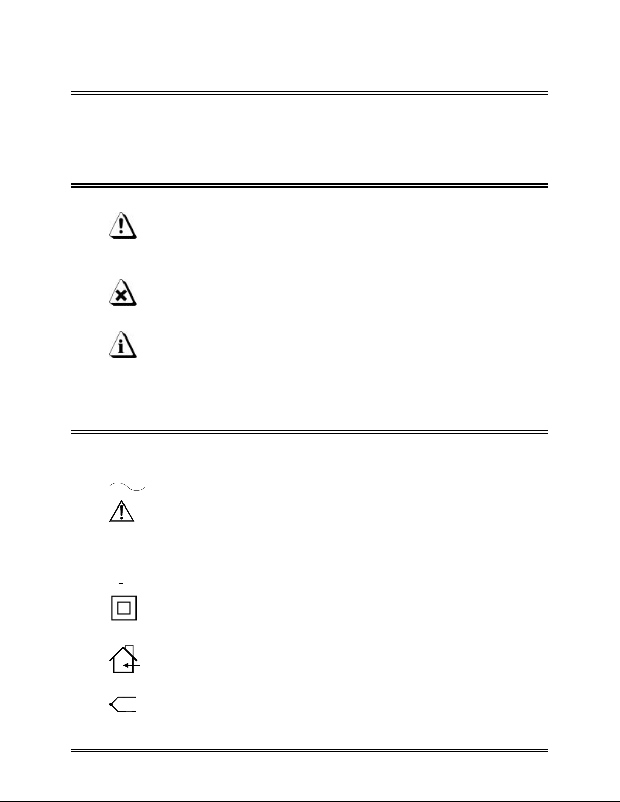
•• Product Symbols
The following symbols may be present on the Product:
• Direct Current (DC) Power
• Alternating Current (AC) Power
• CAUTION: Whenever this internationally recognized symbol is used
on the product, additional information concerning that particular
feature or function appears in the manual.
• Frame or Chassis Terminal
• Battery Charger protected throughout by double or reinforced
insulation.
• Indoor use only. For electric-shock protection, always operate the
battery charger in a protected, indoor location.
• Thermocouple connection
OM-5000 uivu
Page 5

Operator Safety Information
The safety information in this summary is for the benefit of operating personnel.
Warnings and Cautions will also be found throughout the manual where they apply.
PRODUCT USAGE WARNINGS:
For fire and electric shock protection, DO NOT connect the input channels to objects at
elevated electrical potential. The common terminal of each measurement input channel
is not isolated from the common terminal of the input power connector and the RS-232
serial data port while that channel is being measured.
This interconnected common circuitry is not connected to ground or to the
enclosure of the Logger. If the Logger is interconnected to a desktop computer,
its internal circuitry very likely could be connected to ground through the serial
data port of the computer. The Logger enclosure and the measurement circuitry
provide functional isolation of the measurement and data circuitry sufficient to
allow for small electrical noise-related potentials to occur. This functional
isolation is not intended for electrical safety isolation. Therefore for electricshock protection and to prevent fire and damage to data interconnect wiring due
to high currents, the input channels must not be connected to objects at elevated
electrical potential.
• Do not operate the Logger in flammable or explosive atmospheres. Such usage
constitutes a fire or explosion risk.
• For electric-shock protection, only operate the AC power adapter indoor
location.
• For continued fire and electric shock protection, use only the specified power
adapter.
• For continued fire protection, use only the specified optional DC power cable,
which incorporates a two-ampere fuse.
A two-ampere fuse is incorporated in the cigarette lighter plug which is part of
the DC power cable. This fuse provides overcurrent protection should a short or
overload circuit occur in the Logger or the DC power cable.
OM-5000 uvu
Page 6

For protection of the Logger itself, observe the following:
• Do not immerse the Logger in liquids.
• Do not subject the Logger to sharp impacts or drops.
• Do not expose the Logger to corrosive environments.
• Extended exposure to temperatures below the specified minimum may
damage the battery (optional external rechargeable battery pack only).
• Extended exposure to temperatures above the specified maximum may
damage the Logger itself or its optional external rechargeable battery pack.
• Do not excessively stress the power input, the RS-232 serial data, and the
accessory port connections.
The warranty will not cover damage caused by neglect or abuse of this product.
To maintain the safety features incorporated in this product, operation must be in
strict compliance with the requirements specified herein.
OM-5000 uviu
Page 7

1.0 GENERAL INFORMATION AND FEATURES
This section explains the Features for the OM-5100 (Bench Top) and OM-5200 (Wall
Mount) Systems.
1.1 INTRODUCTION & SYSTEM OPERATION
Omega's digital Logger can be furnished with a variety of multiplexers and other
circuitry for various logging tasks.
The Logger is completely self-contained and equipped with a built-in 24-column
thermal printer, an alphanumeric keyboard, a 16-digit vacuum-fluorescent display, a
real-time clock (with rechargeable 30-day battery backup), and an RS-232 serial data
port for connection to a computer serial port.
An AC Power Adapter provides 12 V DC for powering the Logger. North American and
selected international configurations of this power adapter are available.
The Logger includes a Data Cache memory that provides temporary storage of logged
data for reviewing before printing or uploading to a remote computer. RS-232 cable for
connecting to a computer, Accessory board with an external print trigger input; Relay
contact signal outputs for high and low alarms; and an optically isolated serial interface
for use with optional accessories such as the 20-relay alarm card. Also available are:
carrying case, and cables for operating from an automotive 12V DC source.
The Logger can be programmed directly from the keyboard or from a remote computer.
Programmable functions include:
1. Current date, time, and log interval.
2. The contents and format of the printout.
3. The configuration of each channel to match the kind of sensor to be used, such
as thermocouple type, voltage input, and pH probes.
4. The number of channels scanned and which channels are to be skipped. Also
the dwell time between channels and a hold command for continuous logging of
one selected channel.
5. Scaling the display reading to accommodate various input sensors by
multiplying, adding, or subtracting (mX+b).
6. High and low alarm points.
7. Engineering units.
8. Default unit of temperature (C or F).
9. Nonvolatile storage of the configuration for your system in an electrically
programmed ROM.
OM-5000 u1u
Page 8
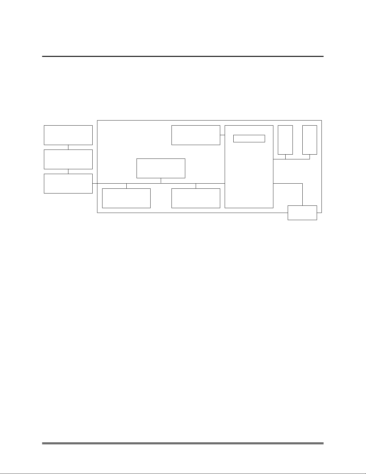
1.1.1 LOGGER MAINFRAME
The Logger Mainframe, as diagramed in Figure 1-1 consists of a microprocessor with
internal EEPROM and external RAM and ROM. The printer, display, and real-time clock
subsystems communicate with the CPU over a serial bus. The processor also receives
data from a 24-key keyboard and is capable of communication to external computers or
devices through the RS-232 port. The serial (SPI) bus is also used to communicate
control and input information to the MUX, Accessory, and Alarm cards.
ALARM
CARD
ACCESSORY
POD
MULTIPLEXOR
DISPLAY
SPI BUS
PRINTER CLOCK
Figure 1-1: Mainframe Block Diagram
KEYBOARD
EEPROM
CPU
R
A
M
RS-232
R
A
M
OM-5000 u2u
Page 9
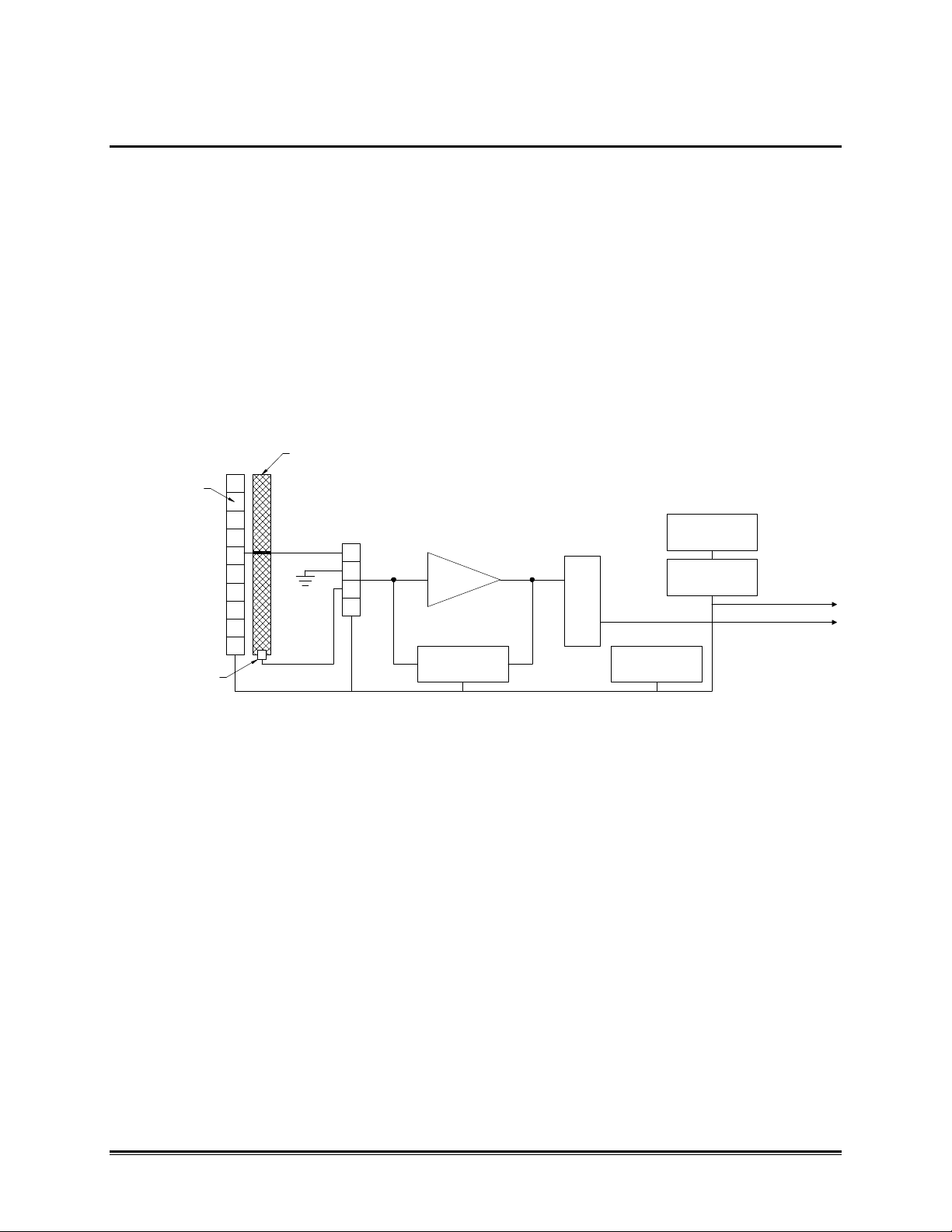
1.1.2 MULTIPLEXER
Multiplexers perform the signal conditioning functions for the Logger. The multiplexer
shown in the block diagram below is designed for use with thermocouple and voltage
inputs. Relays select which input (voltage or thermocouple) is to be read. The input
signals are amplified and digitized by the A/D converter. Provision is also made for
measuring the temperature at the thermocouple attachment point and the system zerovoltage input. Using these parameters, thermocouple readings are compensated for
junction temperature, and offset zero drifts are canceled. The CPU controlled range
switch is set according to the type of input that is selected. Information as to the
channel type, display units, and alarm points is stored in EEPROM in the multiplexer,
allowing you to change multiplexers without losing channel configuration information.
The plug-in accessory board and optional Alarm Cards can be plugged into the
multiplexer.
THERMAL BAR
RELAY MUX
COLD JUNCTION
SENSOR
SS MUX
AMP
A/D
RANGE
SWITCH
EEPROM
Figure 1-2: Typical Multiplexer Block Diagram
ALARM
CARD
ACCESSORY
SPI BUS
TO CPU
OM-5000 u3u
Page 10
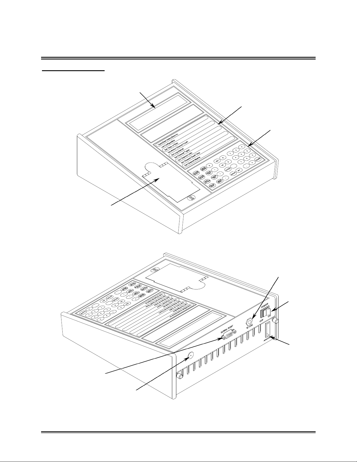
1.2 LOGGER EXTERIOR FEATURES
OM-5100 Features:
DISPLAY
PAPER COVER
QUICKSTART
INSTRUCTIONS
KEYPAD
RS-232 CONNECTOR
Figure 1-3
12V POWER
JACK
POWER
SWITCH
OPTIONAL
ACCESSORY
CONNECTOR
HORN
Figure 1-4
OM-5000 u4u
Page 11
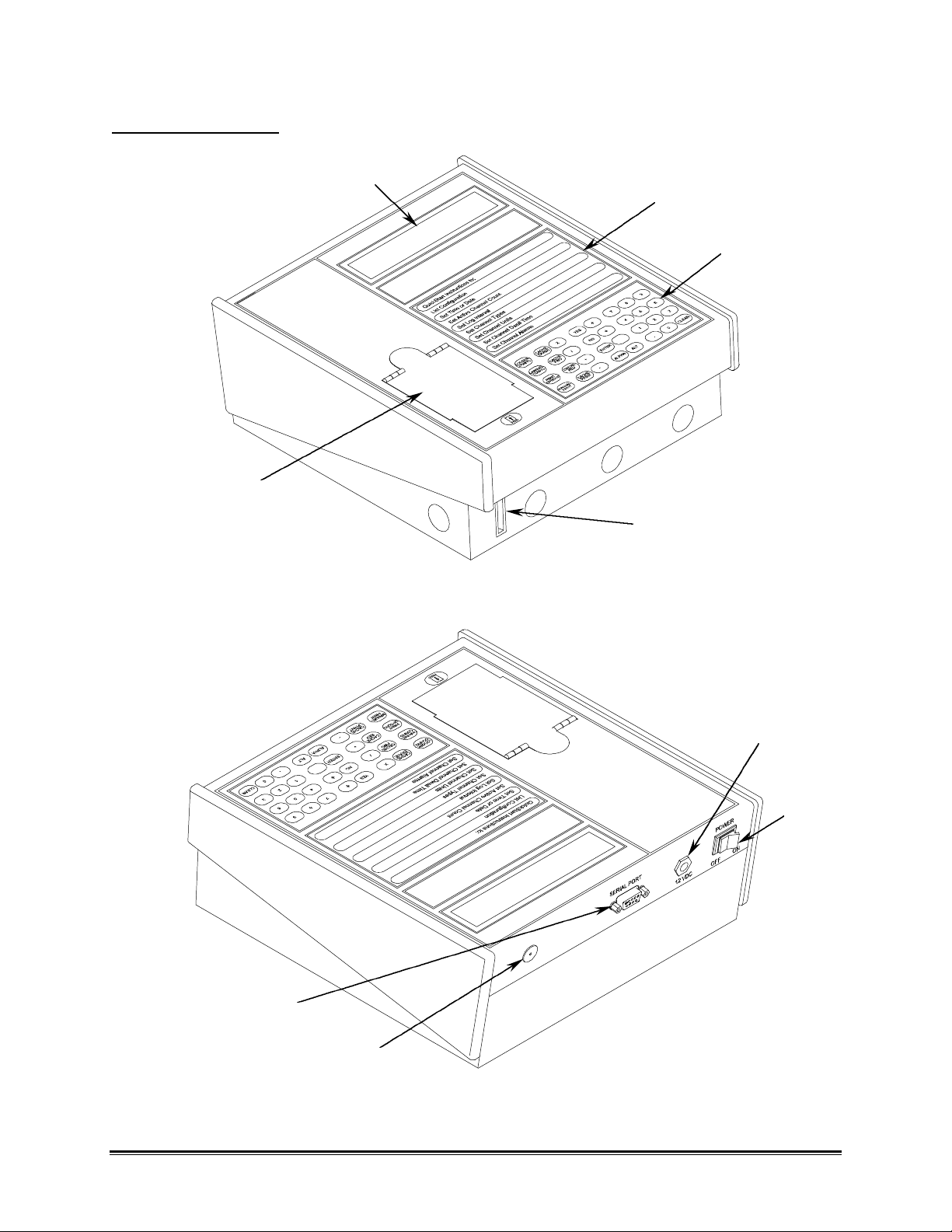
OM-5200 Features:
PAPER COVER
DISPLAY
QUICKSTART
INSTRUCTIONS
KEYPAD
OPTIONAL
ACCESSORY
CONNECTOR
Figure 1-5
12V POWER
JACK
POWER
SWITCH
RS-232 CONNECTOR
HORN
Figure 1-6
OM-5000 u5u
Page 12
2.0 PREPARATION AND SET-UP
This section provides the necessary information to set the Logger up for proper
operation.
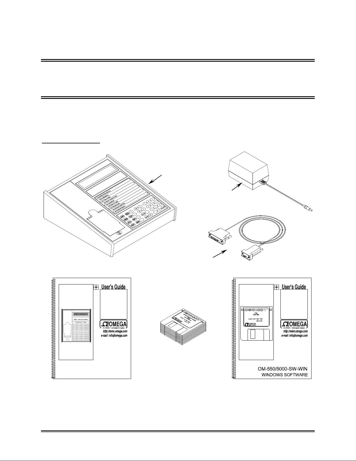
2.1 UNPACKING
Unpack the unit carefully. Check for options and accessories that may have been
packed separately. Retain the shipping carton for reshipment (for recalibration or any
other purpose).
OM-5100 System:
OM-5100
AC POWER
ADAPTER
OM-5100 and OM-5200
Programmable Dataloggers
OM-5000SERIES
USERS GUIDE
RS-232 CABLE
OM-550/5000
WINDOWS SOFTWARE
OM-550/5000 WINDOWS
SOFTWARE USERS GUIDE
Figure 2-1: OM-5100 System
OM-5000 u6u
Page 13
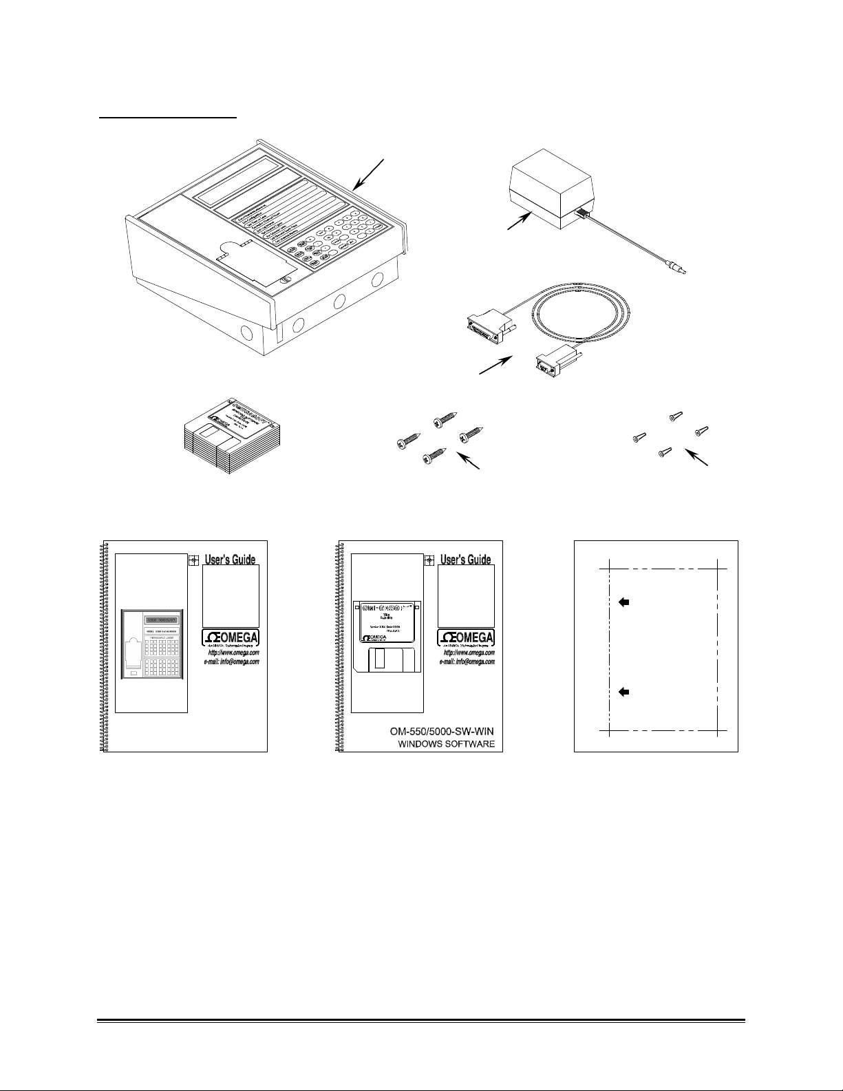
OM-5200 System:
DATAWORKER 10/40 WALL TEMPLATE
OM-5200
AC POWER
ADAPTER
RS-232 CABLE
OM-550/5000
WINDOWS SOFTWARE
OM-5100 and OM-5200
Programmable Dataloggers
OM-5000SERIES
USERS GUIDE
WALL MOUNT
SCREWS (4)
OM-550/5000 WINDOWS
SOFTWARE USERS GUIDE
Figure 2-2: OM-5200 System
WALL MOUNT
PLUGS (4)
THIS SIDE UP
OM-5200
WALL MOUNT TEMPLATE
OM-5000 u7u
Page 14
2.2 QUICK HOOK UP
If you have an OM-5200 System or do not want to attach your Logger to the wall, go directly to
the section 2.4 CONNECTING TRANSDUCER INPUTS TO MULTIPLEXER.
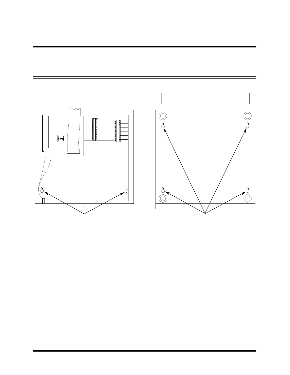
2.3 ATTACHING A OM-5200 TO THE WALL
This procedure is for the OM-5200 ONLY.
INTERNAL VIEW EXTERNAL VIEW
MOUNTING
HOLES
Figure 2-3: Mounting Holes
MOUNTING
HOLES
Locate the Wall Mount template. Observe the indicated setbacks from obstructions
when placing the template. Mark four mounting hardware locations on the wall. Drill
holes for the hardware and insert the anchors into the drilled holes. Tighten the screws
into the anchors until only about 1/4 inch is exposed. Slide the key-hole-shaped
mounting holes in the bottom of the Logger over the screws. It is important that there be
space around the Logger for the printout paper.
The Knock-out tabs in the base may be used for conduit entry if more permanent
installation is desired.
OM-5000 u8u
Page 15
2.4 CONNECTING TRANSDUCER INPUTS TO MULTIPLEXER
1. If you have an OM-5100, place it on a bench in the normal operating position
and loosen the two MUX attachment thumbscrews on the rear panel. Carefully
slide the Mainframe forward exposing the green quick-disconnect terminal strips.
Now proceed to step #3.
CHANNEL
NUMBER
QUICK-DISCONNECT
TERMINALS
Figure 2 4: Quick-Disconnect Terminals
OM-5000 u9u
Page 16
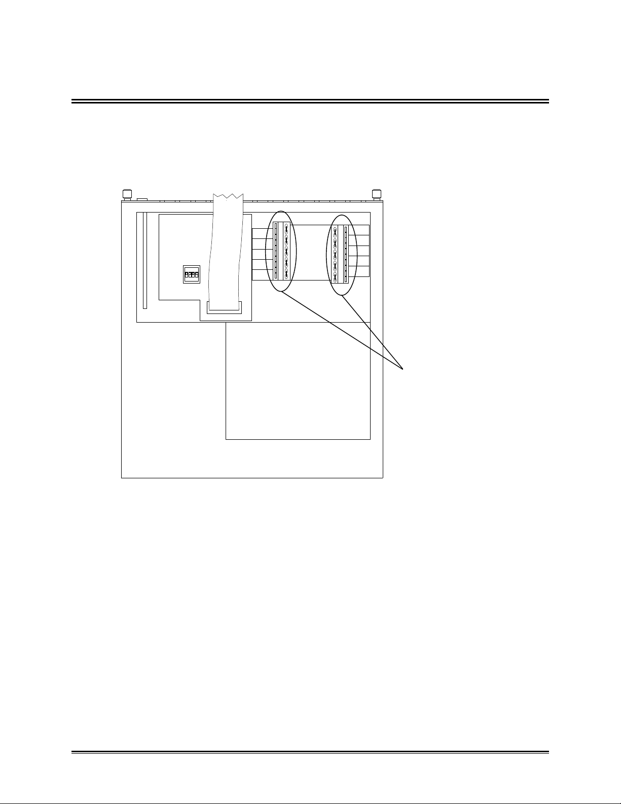
2. If you have a OM-5200, first loosen the thumbscrew on the front of the
mainframe and carefully lifting the Mainframe up, exposing the green quickdisconnect terminals.
CHANNEL
NUMBER
QUICK-DISCONNECT
TERMINALS
Figure 2- 5: Quick-Disconnect Terminals
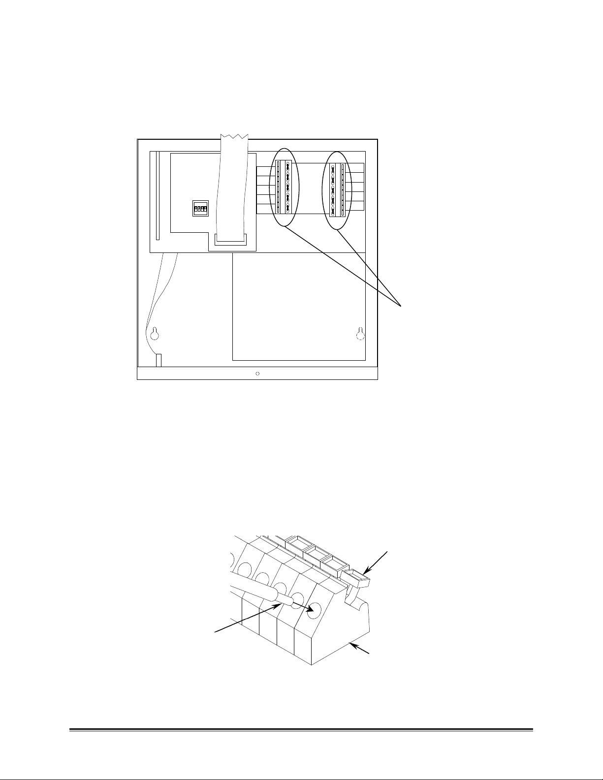
3. Strip 1/4" of insulation from wire ends.
4. Connect each transducer input by pressing down the corresponding small
orange terminal tab on the green terminal strip, inserting the wire into the hole
(approx. 1/2") and releasing the tab. Make sure the wire is pushed far enough
into the hole to engage the locking device. This can be tested by lightly pulling
on the wire after insertion. A problem will occur if the wire is not stripped back far
enough (1/4"), and insulation interferes with the connection.
TERMINAL TAB
WIRE
TERMINAL STRIP
Figure 2-6: Connecting a Terminal
OM-5000 u10u
Page 17
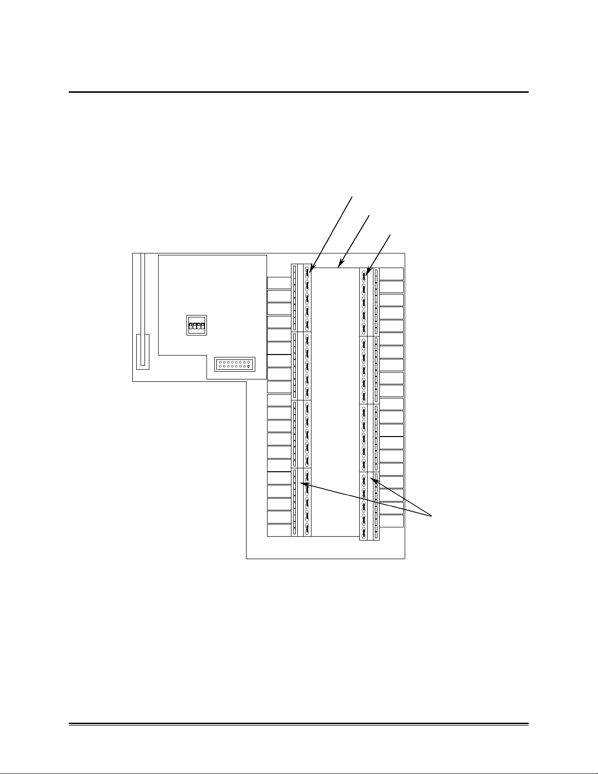
2.4.1 CONNECTING TRANSDUCERS TO THE TV-10/40 MUX
CHANNEL NUMBERS
The TV-10 and TV-40 multiplexers are designed to accept any of type J,K,B,S,R, or T
thermocouples. Channels are numbered from top to bottom and labeled on the Thermal
bar. For best accuracy the thermocouple leads should be placed as close as possible
to the thermal bar and covered to eliminate any drafts or thermal gradients. Channel
type (either J,K,B,S,R, o or V) must be programmed from the front panel (refer to
section 3.2.3.2 CHANNEL TYPE KEYS (J,K,T,E,B,S,R,Volts, Pt & SKIP)).
CHANNEL #2
THERMAL BAR
CHANNEL #1
QUICKDISCONNECT
TERMINALS
Figure 2-7: TV-40 Multiplexer Quick-Disconnect Terminals and Thermal Bar
OM-5000 u11u
Page 18
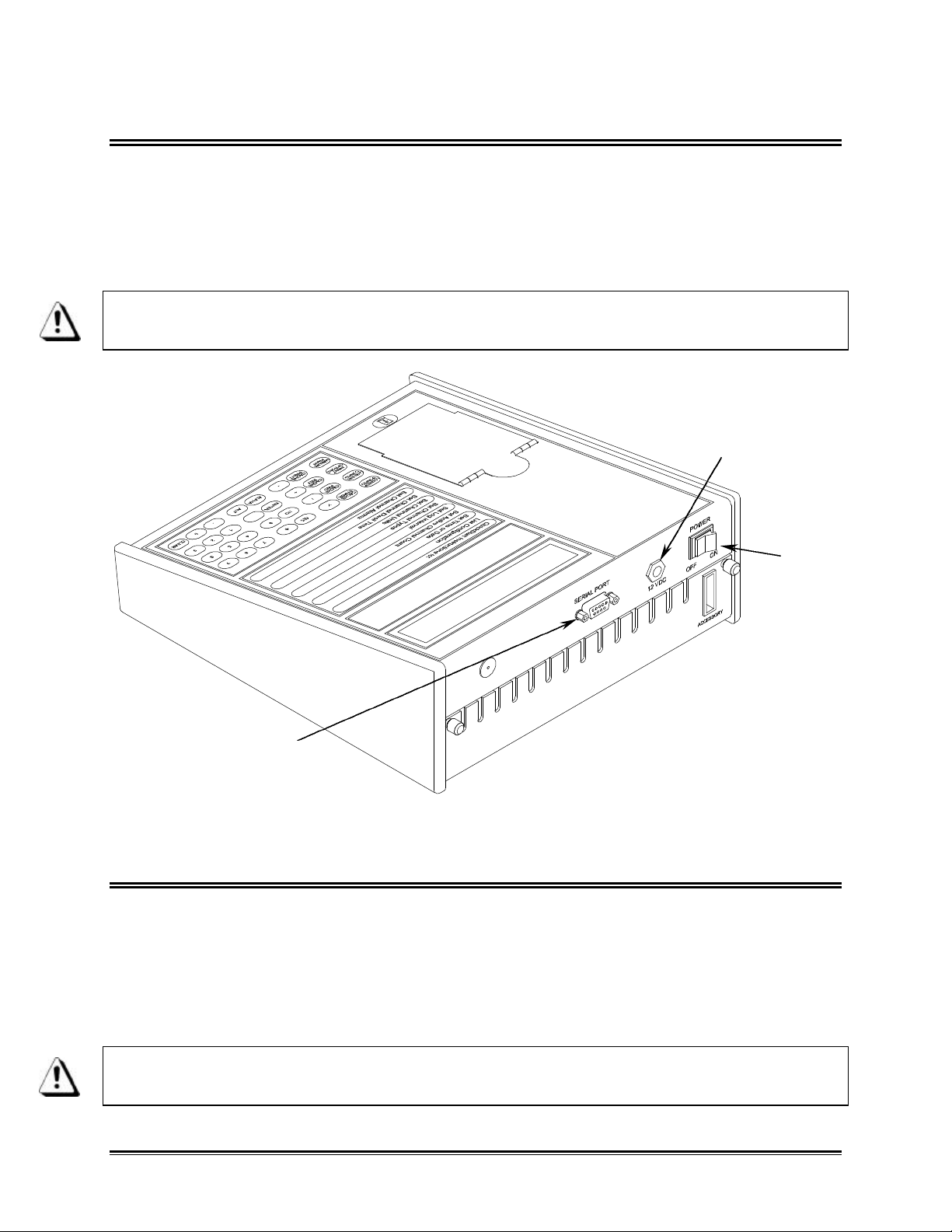
2.5 CONNECTING IN THE AC POWER ADAPTER
1. Turn the power switch on the rear panel of the Logger to the “OFF” position.
2. Plug the small DC connector of the power supply into the 12V power connector
on the rear panel.
3. Plug the AC Power Adapter into the wall outlet.
For continued fire and electric-shock protection, use only the specified AC Power
Adapter.
12V POWER JACK
POWER
SWITCH
RS-232 SERIAL PORT
Figure 2-8: OM-5100 Rear Panel
2.6 CONNECTING OPTIONAL DC POWER CABLE
1. Turn the power switch on the rear panel to the “OFF” position.
2. Plug the small DC connector of the 12V DC Cable into the DC connector on the
rear panel.
3. Plug the large DC cable connector into a 12V DC cigarette lighter power outlet,
whether in the optional rechargeable battery pack or in a motor vehicle.
For continued fire protection, use only the specified DC power cable which
contains a two-ampere fuse.
OM-5000 u12u
Page 19
2.7 GROUNDING THE ENCLOSURE
WINDOW
The rear panel incorporates a threaded chassis-connection point, identified with the "chassis
connection" symbol, which may be used for grounding the enclosure should the user desire to do so.
This terminal is not required to be used for "protective grounding" because the unit is only powered
by the low-voltage Power Adapter or optional rechargeable battery pack. Also, the measurement
circuits must not be connected to hazardous circuits. The enclosure is functionally isolated from the
internal circuits.
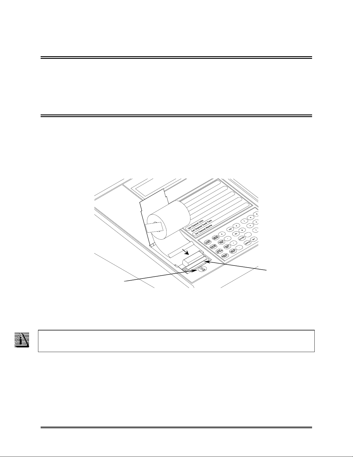
2.8 PAPER INSTALLATION
1. Unwind several inches of paper from the paper roll.
2. Fold the end of the thermal paper over creating a straight flat edge. This creates
a strong paper edge and allows the paper properly center in the printer when
inserting it into the rear paper slot on the printer. As shown in Figure 2-9 the
thermally sensitive side (printing side) of the paper is down.
FRONT
PAPER “FEED” KEY
Figure 2-9
3. Insert the paper into the rear printer slot as shown in Figure 2-9. Turn the Logger
“ON”, then press and hold the FEED key to feed the paper through the printer.
Paper orientation is important because only one side is coated for thermal
printing.
4. After the paper appears in the front window, pull several inches through.
5. Test the operation of the printer & paper-feed mechanism by turning the unit
“OFF” and back “ON”. When finished examine the printed messages for clarity.
OM-5000 u13u
Page 20
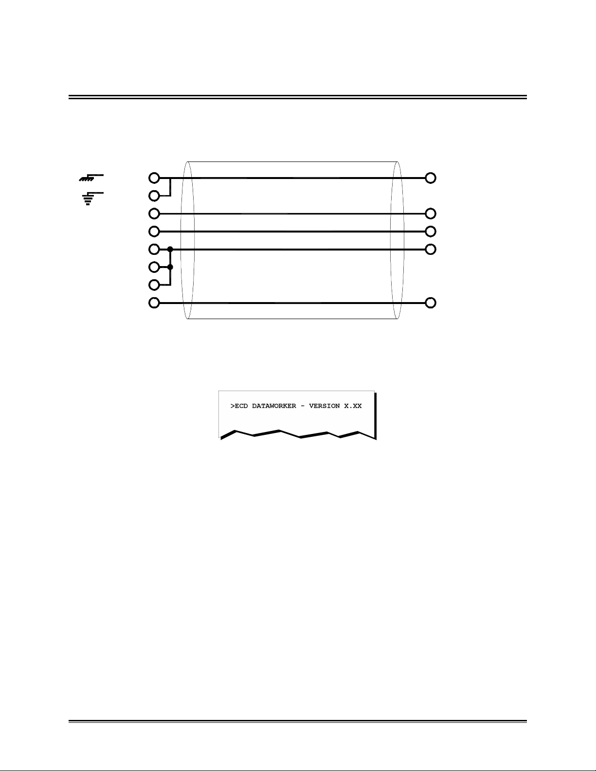
2.9 RS-232 FUNCTIONS
The Logger is equipped with an RS-232 communication interface. The RS-232 port is configured 8
bits, 1 stop, 1 start and no parity. Baud rate is selected from the front panel. (Refer to section
3.2.2.4 BAUD RATE).
1
5 GND
7
RXD
TXD
DSR
CTS
DCD
DTR 4 DTR
Interface operation can be tested by connecting the terminal, then turning on the Logger. A sign-on
message similar to the following should appear:
3
2
6
5
8
20
TXD2
RXD3
DSR6
Figure 2-10: R2-232 Cable Wiring
Figure 2-11: Sign on Message
OM-5000 u14u
Page 21
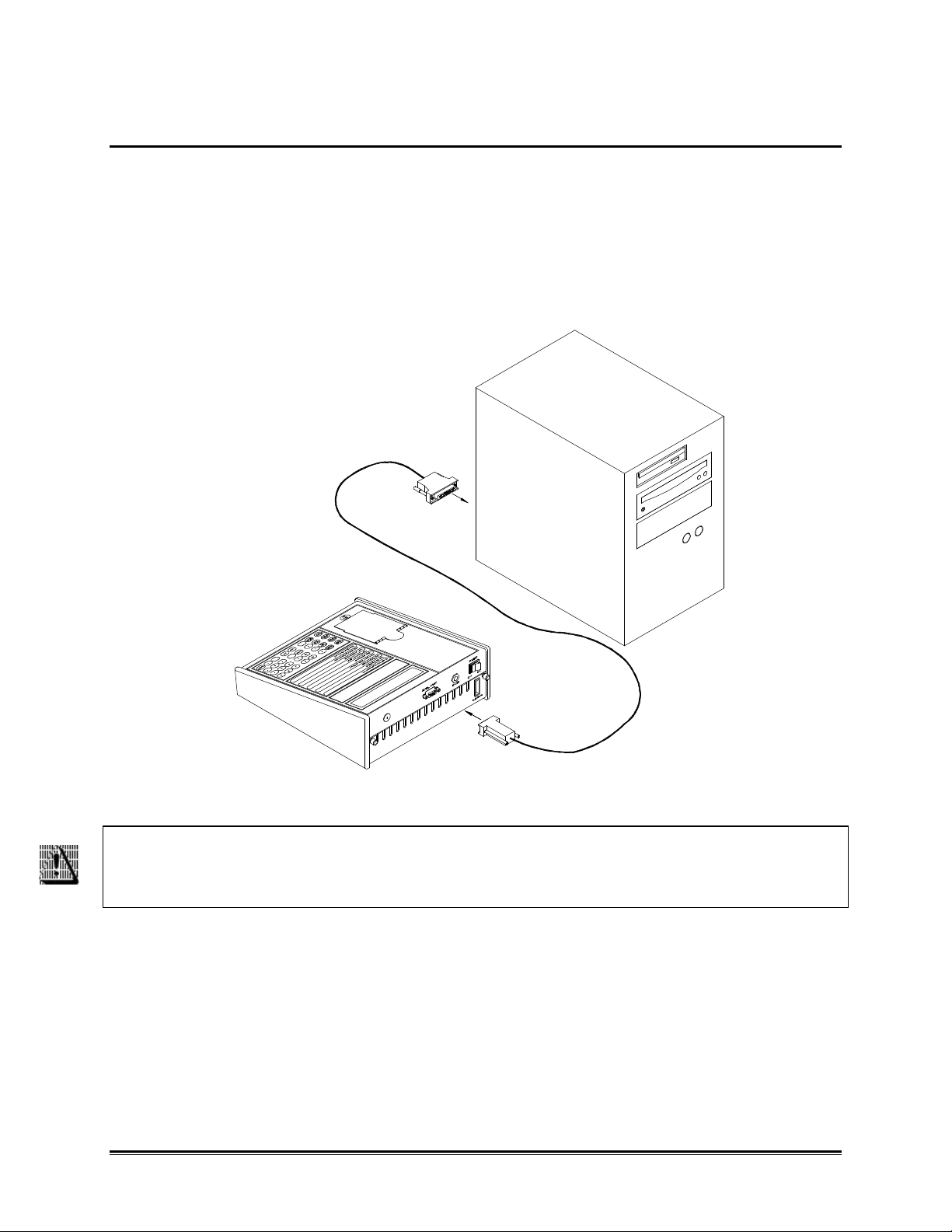
2.9.1 DATA PORT CONNECTION
When the Logger is logging, data is saved in the internal cache RAM. The OM550/5000 Windows software supplied with the Logger is used to transfer this data
through the RS-232 Serial Port to a PC for analysis and storage. Prior to transferring
data, the Logger must be connected to a PC with the supplied RS-232 cable assembly.
The cable is fitted with a 9-pin connector for the Data Port on Logger and a 25-pin
connector for the PC COM port.
Figure 2-12
To minimize danger to personnel, and to avoid ground loops which could affect
measurement accuracy, never connect the Logger to a PC and to the signal
inputs simultaneously!
OM-5000 u15u
Page 22
3.0 OPERATION
DISPLAY
The following section covers the functionality and programming of the Logger for proper operation.
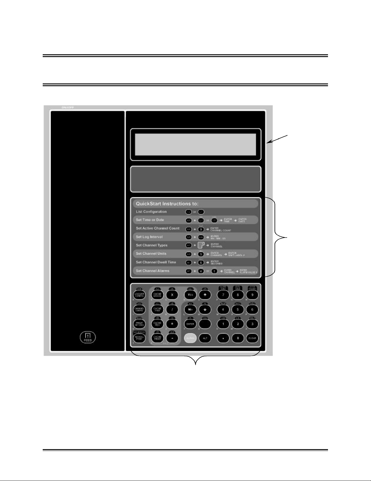
3.1 FRONT PANEL
The front panel includes a Display, Keypad, and Quick Start Instructions.
KEYPAD
Figure 3-1
QUICK START
INSTRUCTIONS
OM-5000 u16u
Page 23
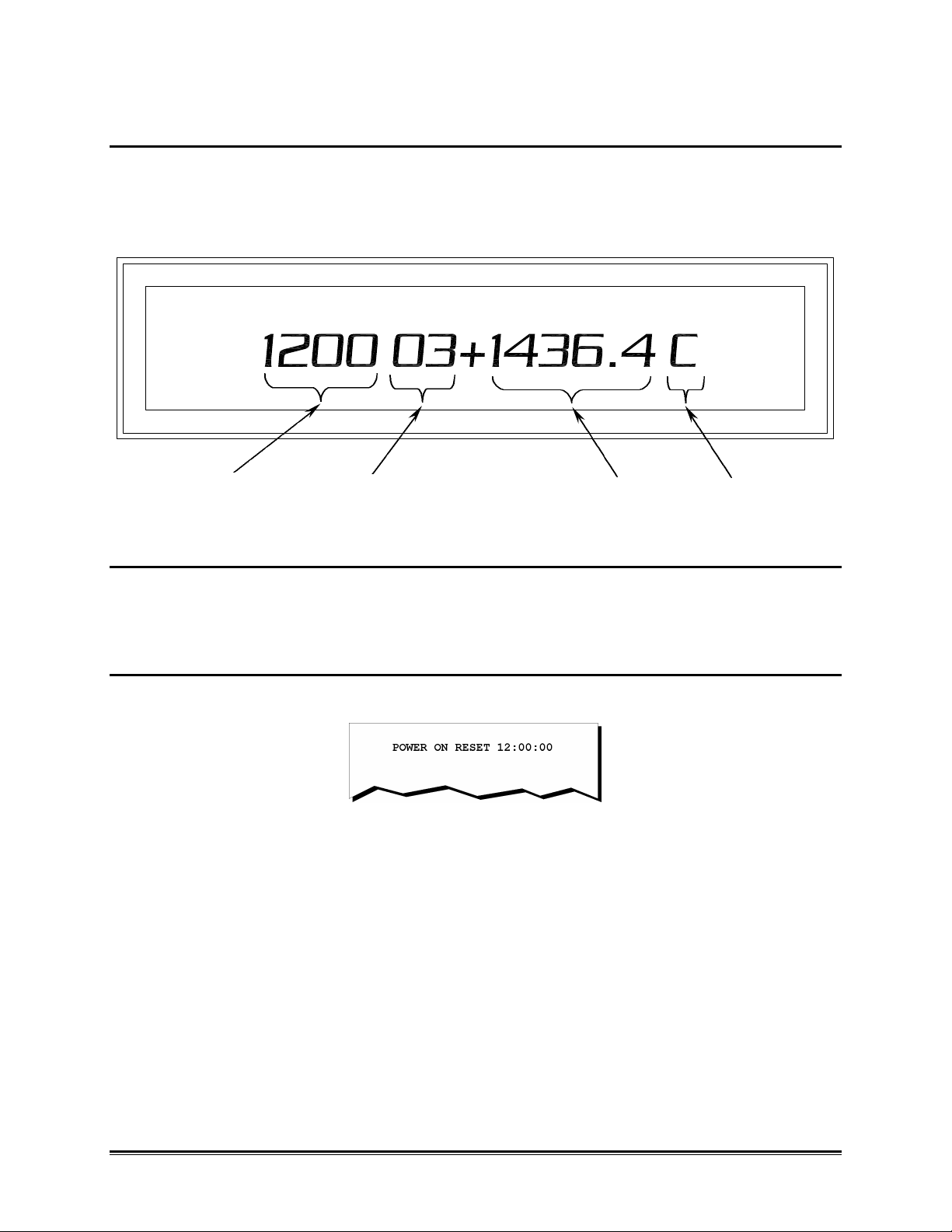
3.1.1 DISPLAY
The Logger display is used for displaying current channel data and prompting programming. When
logging, the display indicates the current time of day, channel number sign, channel data value, and
engineering units of the data. During programming the operator is prompted by the display for
information about the function being programmed.
DATE
CHANNEL
DATA UNITS
Figure 3-2
3.1.2 PRINTOUTS
The Logger incorporates a built-in 24 column printer that is an integral part of the
operation, The printer records data, prints out Logger program configuration and alarm
messages.
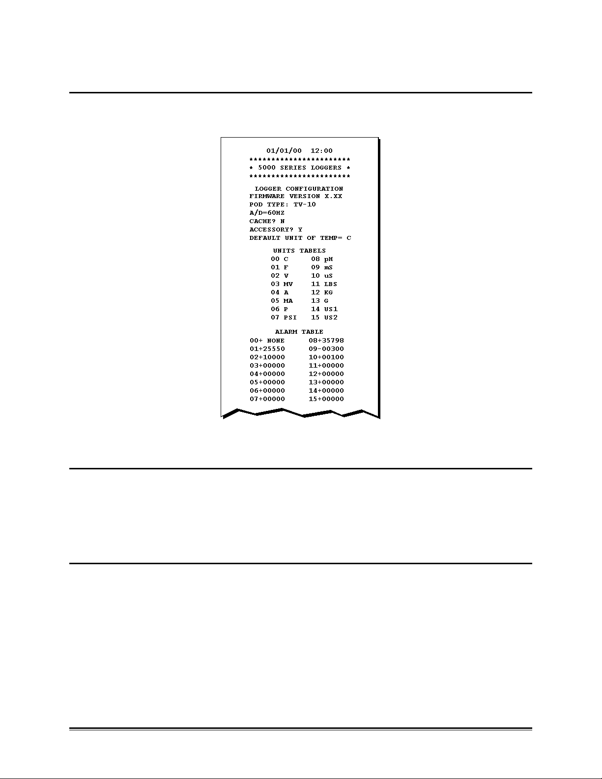
3.1.2.1 POWER UP
When the Logger is initially turned on, the power up message is printed.
Figure 3-3: Power Up Printout
OM-5000 u17u
Page 24
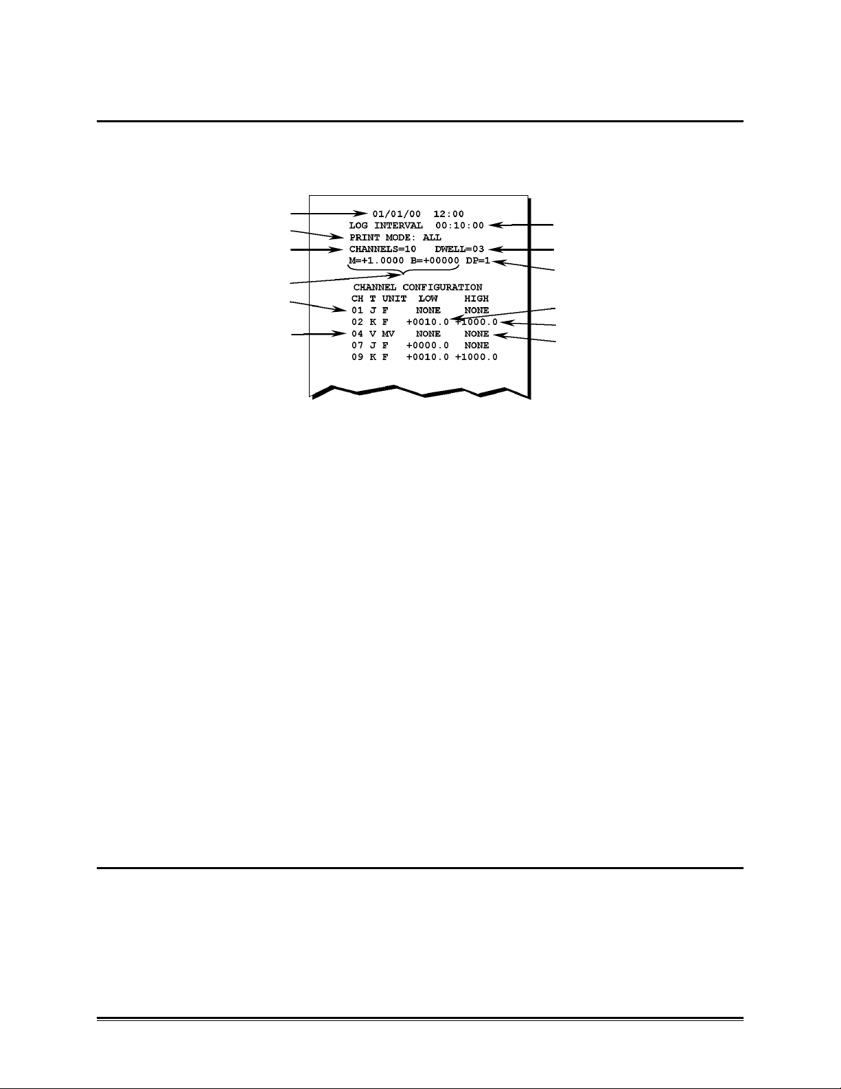
3.1.2.2 LOGGER CONFIGURATION
Pressing the LOGGER CONFIG key causes the Logger configuration to be printed out
on the printer. An example of a configuration printout is shown in Figure 3-4.
Figure 3-4: Configuration Printout
•• CONFIGURATION UNITS TABLE
16 unit labels are listed in a table and may be assigned to any of the Logger channels.
For example, if unit label 04 is assigned to a channel, an "A" will be displayed and
printed following the data on the channel. Unit labels 14 and 15 are user
programmable, and up to a three-character label may be programmed into these table
positions (refer to section• CONFIGURATION UNITS ).
•• CONFIGURATION ALARM TABLE
In a manner similar to the system used for Units Tables shown in Figure 3-4 the Alarms are
assigned to channels by selection from a table of possible numbers. All alarm values except 00
(NONE) are user programmable, and may be either positive or negative. Alarm values are numbers
only and assume the format or decimal printing position of the channel to which they are assigned.
After alarm values are assigned to channels a complete list of channels and alarms can be printed
out by pressing the ALARM TABLE key.
OM-5000 u18u
Page 25
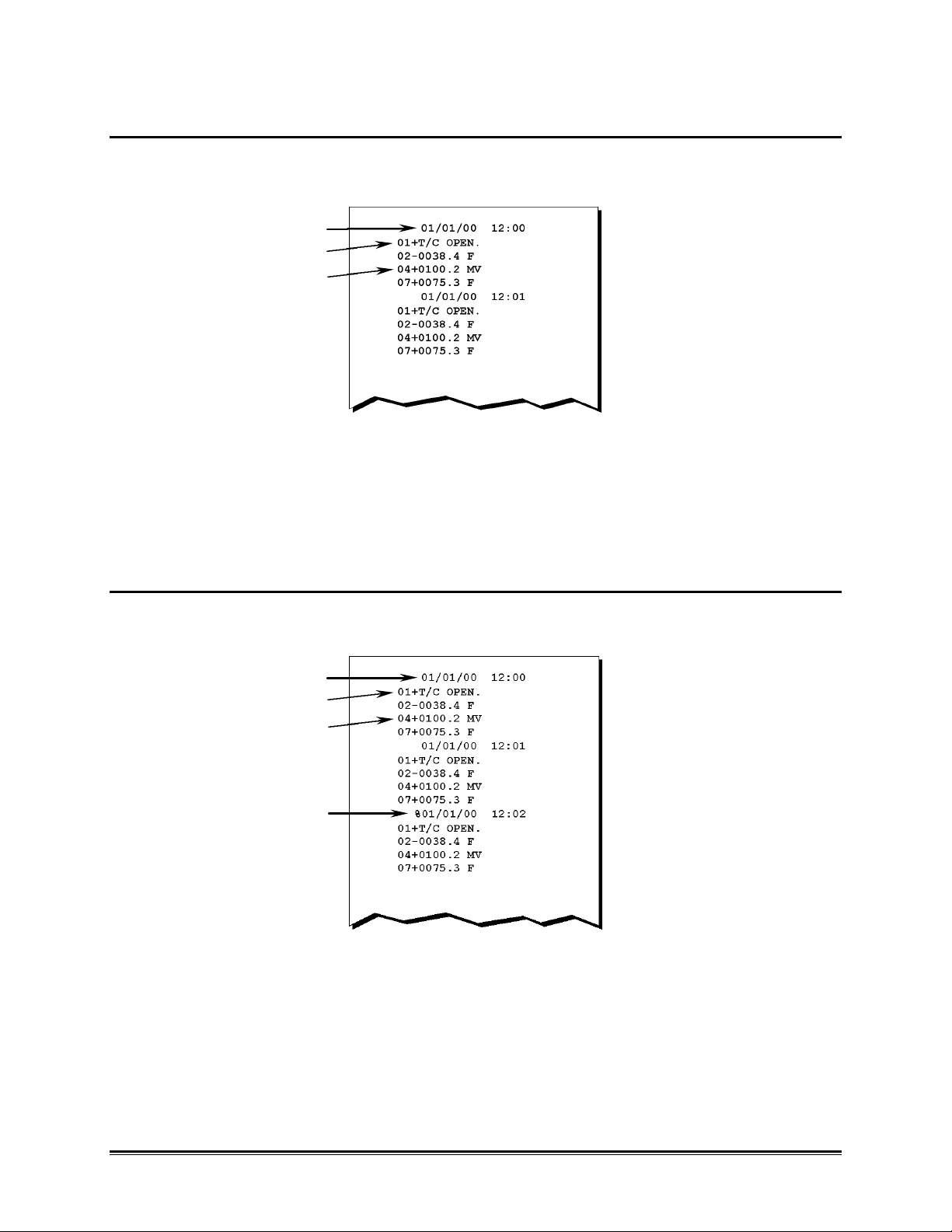
3.1.2.3 CHANNEL CONFIG
(1)
(2)
(3)
(5)
(6)
Pressing the CHANNEL CONFIG key causes the Logger Channel configuration to be
printed out on the printer. An example of a Channel configuration printout is shown in
Figure 3-5.
(4)
(7)
(8)
(11)
Figure 3-5: Channel Configuration Printout
(1) Date & Time
(2) Log Interval is 10 minutes
(3) All channels will print
(4) 10 channels are configured for scanning
(5) Dwell is 3 seconds
(6) Voltage scaling
(7) DP is number of places to right of decimal point
(8) Channels 1 & 7 are Type J Thermocouple
(9)
(10)
(12)
(9) Low alarm for channel 2& 9 is 10.0
(10) High alarm for channel 2 & 9 are 1000.0
(11) Channel 4 is a voltage channel with units = MV
(12) Channel 4 has no alarms
*Channels 3, 5, 6, 8, & 10 are skipped
•• LOG INTERVAL
The Log Interval listed in Figure 3-5 is the time between printouts of all currently enabled channels.
OM-5000 u19u
Page 26

•• PRINT OPTIONS
The Print Options shown in Figure 3-5 determines the amount of data that is sent to the printer. If
the Print Options are set to ALL, all data and alarm information goes to the printer. If the Print
Options are set to ALARMS, only out-of-range alarms are printed. If the Print Options are set to
NONE, no data is printed. In all cases data is sent to the cache memory. If the MANUAL PRINT key
is pressed or an external print trigger is initiated through the accessory port, the Print Options setting
is ignored and normal channel data will be printed.
•• CHANNELS/DWELL
The Channel Configuration information shown in Figure 3-5 documents the maximum channel
number that will be logged. The Dwell is the time in seconds that the Logger sits on a channel before
testing alarm points or saving or printing data.
•• VOLTAGE SCALING
The m, b and DP parameters shown on the Channel Configuration printout indicate the current
scaling and format constants used for channels configured as Voltage. The voltage reading from the
MUX is multiplied by the m constant and then the b constant is added before displaying. The DP
determines how many places will appear to the right of the decimal point when printing voltage
alarms.
•• TADJUST
The Tadjust portion of the Channel Configuration printout shows the number of degrees that
thermocouples are adjusted before printing or displaying.
•• CHANNEL / ALARMS
The Channel Alarm portion of the Channel Configuration printout shows the number, sensor type,
units and alarm points programmed for all active channels.
OM-5000 u20u
Page 27
3.1.2.4 NORMAL LOGGING
When operating the Logger in a normal logging mode the printout appears similar to
the one shown in Figure 3-6.
(1)
(2)
(3)
Figure 3-6: Normal Logging Printout
(1) Date & Time
(2) Channel 1 has an open Thermocouple
(3) Channel 4 reads 100.2MV
3.1.2.5 MANUAL PRINT
Pressing the MANUAL PRINT key on the front panel initiates a printout similar to the normal logging
printout except that the time line is marked with a "%" character.
(1)
(2)
(3)
(4)
Figure 3-7: "MANUAL PRINT" Printout
(1) Date & Time
(2) Channel 1 has an open Thermocouple
(3) Channel 4 reads 100.2MV
(4) Printing was initiated by the Manual Print key or external print trigger.
OM-5000 u21u
Page 28
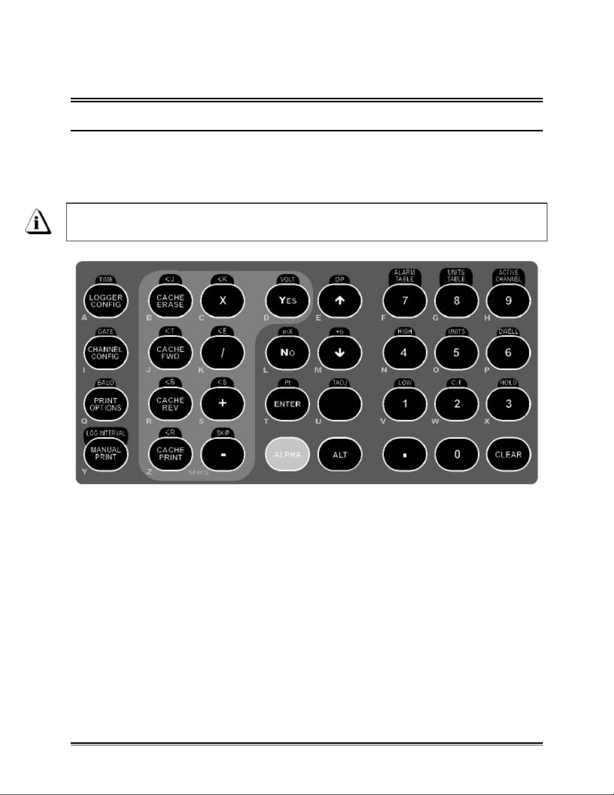
3.2 PROGRAMMING
3.2.1 KEYPAD INTRODUCTION
When programming data into the Logger, be certain that a beep is heard when pressing a key to
insure that the CPU has responded to the keystroke. Most keys perform one primary, one alpha, and
one alternate function. Program data entry is done by displaying an example of how the data is to be
entered and flashing the position at which the data is to be entered. If data out of range for the
function being programmed is entered, the Logger will not accept the data.
In the following instructions and examples, MSD means most significant digit and
LSD means least significant digit.
Figure 3-8: Keypad
OM-5000 u22u
Page 29

3.2.1.1 THE ALPHA KEY
Alpha characters are entered by pressing the ALPHA key, which shifts the key functions to the letters
at the top left of each key. The keyboard remains in the Alpha mode until the Alpha key is pressed
again.
Figure 3-9: Alpha Keys
3.2.1.2 THE ALT KEY
The alternate legends for keys are activated by pressing the ALT key to shift the key functions to the
upper keyboard legend. The Alternate key functions are engaged for one keystroke only.
Figure 3-10: Alternate Key Legend
OM-5000 u23u
Page 30

3.2.1.3 THE CLEAR KEY
The CLEAR key may be pressed at any time to return to the normal operating mode. The Keypad
then returns to its primary function and all keystrokes for the current operation are canceled. All
program entries are automatically stored in memory after the last digit or character is entered for that
operation.
OM-5000 u24u
Page 31

3.2.2 PROGRAMMING MAINFRAME FUNCTIONS
3.2.2.1 MAINFRAME PROGRAM STORAGE
Mainframe program variables are stored in either the real-time clock, or the CPU electrically
alterable RAM. The variables stay with the mainframe even if Multiplexers are changed.
3.2.2.2 TIME
The Logger keeps time in the 24-hour format HH:MM:SS. To enter the time, press the ALT key
followed by the LOGGER CONFIG key. The time currently programmed will appear for 3 seconds,
then Time (HH:MM:SS) appears with the digit ready for entry flashing. If the time is correct, pressing
the CLEAR key will preserve it. To set the time to 14:20:00 enter as follows:
FUNCTION KEY PRESSED DISPLAY
Shift to ALT keyboard ALT SELECT ALTERNATE
Select time LOGGER CONFIG TIME (HH:MM:SS)
Enter MSD hour (tens) 1 TIME (1H:MM:SS)
Enter LSD hour (units) 4 TIME (14:MM:SS)
Enter MSD minutes (tens) 2 TIME (14:2M:SS)
Enter LSD minutes (units) 0 TIME (14:20:SS)
Enter MSD seconds (tens) 0 TIME (14:20:0S)
Enter LSD seconds (units) 0 TIME (14:20:00)
3.2.2.3 DATE
When the DATE key is pressed, the date currently entered in memory will appear for 3 seconds after
which a new date may be entered. If the displayed date is correct, pressing the CLEAR key will
preserve it. Dates are incremented when the time passes from 23:59:59 to 00:00:00. Leap years are
accommodated. The new date is entered in the form MM:DD:YY.
Follow the procedure and example below to enter a new date of 01/01/97:
FUNCTION KEY PRESSED DISPLAY
Shift to alt. keyboard ALT SELECT ALTERNATE
Select DATE CHANNEL CONFIG DATE (MM-DD-YY)
Enter MSD month 0 DATE (0M-DD-YY)
Enter LSD month 1 DATE (01-DD-YY)
Enter MSD day 0 DATE (01-0D-YY)
Enter LSD day 1 DATE (01-01-YY)
Enter MSD year 9 DATE (01-01-9Y)
Enter LSD year 7 DATE (01-01-97)
OM-5000 u25u
Page 32

3.2.2.4 BAUD RATE
The RS-232 port baud rate is selectable as either 9600, 1200, or 600 and is selected by pressing the
YES or NO key in response to the baud rates as they appear.
Follow the procedure below to set the baud rate to 600 baud:
FUNCTION KEY PRESSED DISPLAY
Shift to alt. keyboard ALT SELECT ALTERNATE
Select BAUD PRINT OPTIONS BAUD=9600Y/N ?
NO BAUD=1200Y/N ?
NO BAUD= 600Y/N ?
YES
3.2.2.5 LOG INTERVAL
The Log Interval is a 6-digit entry in the form HH:MM:SS. Logging intervals can range from 1 second
to 23 hours, 59 minutes and 59 seconds, however the log interval should be chosen to log all active
channels before the next log interval starts.
If the log interval is set shorter than the total scan time, the log interval will be “overrun”. The effect of
overrunning the log interval is twofold. First is that your data will not be recorded at the desired time.
Second is that only data is stored in the cache, not time. The Logger calculates the event time using
the time of the last data taken and the log interval. Therefore the time stamp on the printout and
cache printout will not agree.
Set log intervals as follows (the example is for 1 hour, 30 minutes, and
15 seconds):
FUNCTION KEY PRESSED DISPLAY
Shift to alt. keyboard ALT SELECT ALTERNATE
Select log interval LOG INTERVAL INTRVL (HH:MM:SS)
Enter MSD hour 0 INTRVL (0H:MM:SS)
Enter LSD hour 1 INTRVL (01:MM:SS)
Enter MSD minute 3 INTRVL (01:3M:SS)
Enter LSD minute 0 INTRVL (01:30:SS)
Enter MSD second 1 INTRVL (01:30:1S)
Enter LSD second 5 INTRVL (01:30:15)
OM-5000 u26u
Page 33

3.2.2.6 CHANNEL LOGGING KEYS
•• ACTIVE CHANNEL
The Logger allows setting the maximum number of channels to be scanned from 1 to the capability
of the multiplexer (up to 40 in a 40-channel MUX). Enter the desired maximum channels to be
scanned with the following procedure and example (8 channels):
FUNCTION KEY PRESSED DISPLAY
Shift to alt. keyboard ALT SELECT ALTERNATE
Select Maximum channels 9 MAX CHANNELS CC
Enter MSD channel 0 MAX CHANNELS 0C
Enter LSD channel 8 MAX CHANNELS 08
•• DWELL
Dwell time is a 2-digit entry, which can range from 1 to 9 seconds. Enter the desired time using the
following procedure and example (05 seconds dwell):
Dwell time is used to allow the Logger needed time to settle on a channel. The
total time needed is dependent on the input type and is best determined by
experience. Dwell is part of the total scan time and must be taken into
consideration along with Active Channels and Log Interval to get a scan time that
will not be longer than the Log Interval.
FUNCTION KEY PRESSED DISPLAY
Shift to alt. keyboard ALT SELECT ALTERNATE
Select dwell time 6 DWELL SEC NN
Enter MSD second 0 DWELL SEC 0N
Enter LSD second 5 DWELL SEC 05
•• HOLD
The Hold function allows the user to continuously scan on any individual channel. The channel hold
continues until the CLEAR key is pressed.
In the following example: Channel 10 is designated to be put on Hold:
FUNCTION KEY PRESSED DISPLAY
Shift to alt. keyboard ALT SELECT ALTERNATE
Select hold function 3 HOLD CHANNEL CC
Enter MSD of channel 1 HOLD CHANNEL 1C
Enter LSD of channel 0 HOLD CHANNEL 10
OM-5000 u27u
Page 34

3.2.3 PROGRAMMING MULTIPLEXER FUNCTIONS
3.2.3.1 MUX PROGRAM STORAGE
Mainframe program variables are stored in electrically alterable RAM located on the MUX. These
variables are retained even if power is disconnected.
3.2.3.2 CHANNEL TYPE KEYS (J,K,T,E,B,S,R,Volts, Pt & SKIP)
Each channel in the Logger can be individually programmed for measuring voltage (±2.000 volts), or
thermocouples. The availability of thermocouples depends on the type of multiplexer you have.
When programming channels as a thermocouple the default unit of temperature will be assigned to
it. Channels may also be skipped when no logging is desired. Different thermocouple types are
selected from the front panel as J,K,B,S,R or T:
In the following example:
Channel 1 is for a type T thermocouple (Note: Thermocouple-10/40 Mux only)
Channel 4 is for a type K thermocouple (Note: Thermocouple-10/40 Mux only)
Channel 10 is set to read voltage (V) (±2.000 volts max.)
Channel 12 is to be skipped.
FUNCTION KEY PRESSED DISPLAY
Shift to alt. keyboard ALT SELECT ALTERNATE
Select T/C type T CACHE FWD CHANNEL T CC
Enter MSD channel 0 CHANNEL T 0C
Enter LSD channel 1 CHANNEL T 01
Shift to alt. keyboard ALT SELECT ALTERNATE
Select T/C type K X CHANNEL K CC
Enter MSD channel 0 CHANNEL K 0C
Enter LSD channel 4 CHANNEL K 04
Shift to alt. keyboard ALT SELECT ALTERNATE
Select voltage YES CHANNEL V CC
Enter MSD channel 1 CHANNEL V 1C
Enter LSD channel 0 CHANNEL V 10
Shift to alt. keyboard ALT SELECT ALTERNATE
Select skip - CHAN SKIP CC
Enter MSD channel 1 CHAN SKIP 1C
Enter LSD channel 2 CHAN SKIP 12
Shift to alt. keyboard ALT SELECT ALTERNATE
OM-5000 u28u
Page 35

3.2.3.3 VOLTAGE SCALING KEYS
mX + b effects all voltage channels
•• VOLTAGE INPUT SCALING
Any of the Logger input channels may be programmed as Voltage channels. Voltage channels
include m and b constants for "scaling" all voltage data to your application. The following sections
include examples for common transducers.
•• MATCHING TRANSDUCERS TO THE LOGGER
Some transducers provide a "voltage" output others provide a "current" output.
This section explains how to use resistors to “Match” either output to the Logger input.
Currents must be converted to a voltage and voltages must be attenuated (reduced) if they can
exceed the Logger maximum input (±2.0000 VDC). This process is called Matching, which means
converting or attenuating the transducer's output to an acceptable level without overloading it.
•• MATCHING A VOLTAGE TRANSDUCER
Use two resistors to attenuate a voltage without overloading the transducer. The method shown here
will draw approximately half of the transducer's maximum current at full-scale.
I
TRANSDUCER
OUTPUT
+
R2
R1V LOGGER INPUT
-
Figure 3-11
V = transducer maximum output voltage
I = 1/2 transducer's maximum output current
R1 = 2 / I
R2 = (V-2) / I
OM-5000 u29u
Page 36

•• MATCHING A CURRENT TRANSDUCER
Use one resistor to develop the necessary voltage at the Logger input:
I
+
TRANSDUCER
OUTPUT
-
R1 V DATAWORKER INPUT
Figure 3-12
V = Logger maximum input voltage
= 2.0000 VDC
= R1 * I
I = 1/2 transducer's maximum output current
R1 = 2 / I
•• DATA SCALING (mX + b calculation)
The Logger can read the output voltage of a properly matched transducer but the data will be in
"volts" and you might prefer data in units that reflect your application. Programming the Logger to
produce data in terms of the actual parameter being measured is called Scaling.
The linear slope-intercept formula (Y = mX + b) shows how to do this. Given input "X", careful choice
of m and b can scale the output "Y" to any value, with some restrictions:
• The m and b values you choose must be within the allowable ranges:
-9.99999 < m < +9.99999 -999999 < b < +999999
The following equations show how to scale your data to the actual value of the parameter you are
measuring. They assume that an increasing transducer output indicates an increasing parameter. If
your system is inversely proportional, just change the sign of the m value. Remember that m and b
can be positive or negative.
X1 = minimum voltage expected at the Logger input
X2 = maximum voltage expected at the Logger input
Y1 = minimum parameter value for your application
Y2 = maximum parameter value for your application
m = (Y1-Y2) / (X1-X2) b = Y2 - (m * X2)
OM-5000 u30u
Page 37

•• EXAMPLE - VOLTAGE TRANSDUCER
EXAMPLE:
Given a 20 - 90 % RH (Relative Humidity) transducer with a 0 - 10 VDC output and a maximum
current of 3 mA.
Program the Logger to indicate 20.00 %RH to 90.00 %RH (that is, to indicate %RH with 0.01%
resolution).
1. First, find the Matching resistors:
I = 1/2 maximum current
= 0.003 / 2
= 0.0015 Amps
R1 = 2 / I R2 = (V - 2) / I
= 2 / 0.0015 = (10 - 2) / 0.0015
= 1333 Ω = 5333 Ω
2. Check:
V = (R1 + R2) * I V = R2 * I
= (1333+5333)*1.5 mA = 1333*1.5 mA
= 9.999 = 1.9995
= 10 = 2
When the transducer output is 10 VDC, the Logger will see 2 VDC.
OM-5000 u31u
Page 38

3. Next, find m & b:
X1 = 0 VDC ç minimum expected Logger input
= 0 A/D counts
X2 = 2.0000 VDC ç Logger maximum allowable input
= 20000 A/D counts
Y1 = 20.00 %RH ç choose decimal point = 2
= 2000 A/D counts
Y2 = 90.00 %RH ç keep decimal point = 2
= 9000 A/D counts
m = (Y1 - Y2) / (X1 - X2)
= (2000 - 9000) / (0 - 20,000)
= 0.35000
b = Y2 - (m * X2)
= 9000 - (0.350 * 20,000)
= 002000
Notice the decision to indicate with 0.01% resolution determined a decimal
position of 2.
OM-5000 u32u
Page 39

•• EXAMPLE - CURRENT TRANSDUCER
EXAMPLE:
Given a 0 - 150 PSI transducer with a 4-20 mA output.
Program the Logger to indicate 0 - 150 PSI with 0.01 PSI resolution.
1. First, find the Matching resistor:
R1 = 2 / I
= 2 / 20 mA
= 2 / 0.02
= 100 Ω
When the transducer output is 4 mA, the Logger will see 0.4 VDC and when the transducer output is
20 mA, the Logger will see 2 VDC.
2. Next, find m & b:
X1 = 0.4000 VDC ç minimum expected Logger input
= 4000 A/D counts
X2 = 2.0000 VDC ç Logger maximum allowable input
= 20000 A/D counts
Y1 = 0 VDC ç minimum transducer output
= 0.00 PSI ç choose decimal point = 2
Y2 = 150.00 PSI ç maximum transducer output
= 15000 A/D counts ç keep decimal point = 2
m = (Y1 - Y2) / (X1 - X2)
= (0 - 15000) / (4000 - 20000)
= 0.93750
b = Y2 - (m * X2)
= 15000 - (0.93750 * 20000)
= -003750
Notice the decision to indicate with 0.01 PSI resolution determined a decimal
position of 2
OM-5000 u33u
Page 40

•• PROGRAMMING EXAMPLE
mX + b effects all voltage channels
In the following example: The mX+b equation is set so that m = +.6666 and b = -00010. (Range of
allowable values for b are -32767 to +32767 and allowable values for m are -9.9999 to 9.9999)
FUNCTION KEY PRESSED DISPLAY
Shift to alt. keyboard ALT SELECT ALTERNATE
Select m coefficient NO M COEF +N.NNNN
Select the positive sign + M COEF +N.NNNN
Enter the MSD 0 M COEF +0.NNNN
Enter the NSD 6 M COEF +0.6NNN
Enter the NSD 6 M COEF +0.66NN
Enter the NSD 6 M COEF +0.666N
Enter the LSD 6 M COEF +0.6666
Shift to alt. keyboard ALT SELECT ALTERNATE
Select b coefficient DOWN ARROW B COEF +NNNNN
Select the negative sign - B COEF -NNNNN
Enter the MSD 0 B COEF -0NNNN
Enter the NSD 0 B COEF -00NNN
Enter the NSD 0 B COEF -000NN
Enter the NSD 1 B COEF -0001N
Enter the LSD 0 B COEF -00010
•• DECIMAL POINT
The decimal point may be set at any position. In the following example, any number from 0 to 5 may
be entered when the display shows DECIMAL POS=N with the N flashing. The number entered
determines the number of places from the right that the point will appear.
In the following example: The decimal point is set to the hundredths position (000.00), that is 2
places from the right. The range of possible locations are .nnnnn to nnnnn.
FUNCTION KEY PRESSED DISPLAY
Shift to alt. keyboard ALT SELECT ALTERNATE
Select decimal point (flashing) UP ARROW DECIMAL POS=N
Enter position 2 2 DECIMAL POS=2
OM-5000 u34u
Page 41

3.2.3.4 TADJUST (TEMPERATURE ADJUSTMENT)
The Logger permits adjustment of the temperature readings to accommodate various thermocouple
sensors. This correction is accomplished by adding the value of Tadjust to actual sensor readings.
The value of Tadjust is cumulative and the number entered adds (or subtracts if negative) to the
Tadjust value already stored in the MUX EEPROM. The accumulated value of Tadjust is shown on
the "Channel Configuration" printout (refer to Figure 3-5: Channel Configuration Printout)
In the following example: Tadjust is increased by 22.5 degrees. The Range of allowable values for
Tadjust is -99.9 to +99.9.
Tadjust effects all channels the same.
FUNCTION KEY PRESSED DISPLAY
Shift to alt. keyboard ALT SELECT ALTERNATE
Select Tadjust TADJUST TADJUST +00XX.X
Select the positive sign + TADJUST +00XX.X
Enter the MSD 2 TADJUST +002X.X
Enter the NSD 2 TADJUST +0022.X
Enter the LSD 5 TADJUST +0022.5
If a channel's type is such that the temperature readings are only accurate to one
degree resolution (e.g. B,S or R thermocouple), only the integer portion of
Tadjust ahead of the decimal point is added.
OM-5000 u35u
Page 42

3.2.3.5 ALARM KEYS
•• ALARM TABLE
The Logger permits assignment of up to 15 alarm values. These alarm values are put in a table, and
may be assigned to any channel as a high or low alarm (refer to section• HIGH and LOW). Alarm
values are of fixed format (only whole numbers) and may be either positive or negative. Alarm
values may be printed by pressing the LOGGER CONFIG key.
In the following example: We will assign a value of +100 to alarm number 01, and a value of -100 to
number 02:
FUNCTION KEY PRESSED DISPLAY
Shift to alt. keyboard ALT SELECT ALTERNATE
Select alarm value 7 ALARM NN+XXXXX
Enter the channel MSD 0 ALARM 0N+XXXXX
Enter the channel LSD 1 ALARM 01+XXXXX
Select the positive sign + ALARM 01+XXXXX
Enter the MSD 0 ALARM 01+0XXXX
Enter the NSD 0 ALARM 01+00XXX
Enter the NSD 1 ALARM 01+001XX
Enter the NSD 0 ALARM 01+0010X
Enter the LSD 0 ALARM 01+00100
Shift to alt. keyboard ALT SELECT ALTERNATE
Select alarm value 7 ALARM NN+XXXXX
Enter the channel MSD 0 ALARM 0N+XXXXX
Enter the channel LSD 2 ALARM 02+XXXXX
Select the negative sign - ALARM 02-XXXXX
Enter the MSD 0 ALARM 02-0XXXX
Enter the NSD 0 ALARM 02-00XXX
Enter the NSD 1 ALARM 02-001XX
Enter the NSD 0 ALARM 02-0010X
Enter the LSD 0 ALARM 02-00100
OM-5000 u36u
Page 43

•• HIGH and LOW
The Logger offers 16 alarm values that can be assigned to any channel as either a high or low alarm.
The channels are assigned first, then the alarm value (HH or LL). If no alarm is desired on a channel,
it may be assigned alarm value 00. The default tag for high and low alarm values is NONE.
In the following example: Channel 01 is assigned a high alarm value of +100, which was assigned
to Alarm Value 01 in the Alarm Value section.
Channel 05 is assigned a low alarm value of -100 as assigned to Alarm Value number 02 in Section
Alarm Value section.
FUNCTION KEY PRESSED DISPLAY
Shift to alt. keyboard ALT SELECT ALTERNATE
Select HIGH for high alarm 4 HI ALM CH CC HH
Enter MSD of channel 0 HI ALM CH 0C HH
Enter LSD of channel 1 HI ALM CH 01 HH
Enter MSD of alarm value no. 0 HI ALM CH 01 0H
Enter LSD of alarm value no. 1 HI ALM CH 01 01
Shift to alt. keyboard ALT Select Alternate
Select LOW for low alarm 1 LO ALM CH CC LL
Enter MSD of channel 0 LO ALM CH 0C LL
Enter LSD of channel 5 LO ALM CH 05 LL
Enter MSD of alarm value no. 0 LO ALM CH 05 0L
Enter LSD of alarm value no. 2 LO ALM CH 05 02
OM-5000 u37u
Page 44

3.2.3.6 UNIT KEYS
•• UNITS TABLES
The Logger has a total of 16 unit labels. The last two, 14 and 15, are programmable with up to 3
characters each. Once the label number is entered numbers maybe entered or by using the ALPHA
key the Keypad shifts to the alpha mode, in which the keys select the alpha characters denoted in
red at the top left of each affected key.
Only labels 14 and 15 can be customized.
In the following example:
Unit label 14 is programmed to read RPM
Unit label 15 is programmed to read MG
FUNCTION KEY PRESSED DISPLAY
Shift to alt. keyboard ALT SELECT ALTERNATE
Select unit label 8 UNIT LABEL NN CCC
Enter MSD unit label no. 1 UNIT LABEL 1N CCC
Enter LSD unit label no. 4 UNIT LABEL 14 CCC
Enter unit label char R UNIT LABEL 14 RCC
Enter unit label char P UNIT LABEL 14 RPC
Enter unit label char M UNIT LABEL 14 RPM
Shift to alt. keyboard ALT SELECT ALTERNATE
Select unit label 8 UNIT LABEL NN CCC
Enter MSD unit label no. 1 UNIT LABEL 1N CCC
Enter LSD unit label no. 5 UNIT LABEL 15 CCC
Enter unit label char SPACE UNIT LABEL 15 CC
Enter unit label char M UNIT LABEL 15 MC
Enter unit label char G Unit LABEL 15 MG
•• UNITS
The Logger offers 16 unit labels that can be assigned to any channel. The list of units available can
be printed out by pressing the LOGGER CONFIG key.
In the following example: We will assign unit label 03 (MV) to channel 01:
FUNCTION KEY PRESSED DISPLAY
Shift to alt. keyboard ALT SELECT ALTERNATE
Select UNIT 5 UNIT CH CC UU
Select channel number MSD 0 UNIT CH 0C UU
Select channel number LSD 1 UNIT CH 01 UU
Select unit number MSD 0 UNIT CH 01 0U
Select unit number LSD 3 UNIT CH 01 03
OM-5000 u38u
Page 45

•• C/F
The C/F key is used to set the default unit of temperature, Celsius or Fahrenheit. This default unit of
temperature is automatically assigned to any new channel that is programmed as a thermocouple.
Changing the default unit of temperature does not change any temperature units
already set. To change a channel’s temperature unit you must reprogram the
channel as a thermocouple or actually change the channel’s units.
The default unit of temperature is programmed by pressing the YES or NO key in response to the
options as they appear.
Use the following procedure to set the default to Fahrenheit:
FUNCTION KEY PRESSED DISPLAY
Shift to alt. keyboard ALT SELECT ALTERNATE
Select C/F 2 TEMP UNIT C Y/N?
NO TEMP UNIT C Y/N? YES
TEMP UNIT F Y/N?
OM-5000 u39u
Page 46

3.3 DATA CACHE FUNCTIONS
The Logger contains a 14.5 K Byte data cache that retains logged data even when the unit is “OFF”.
The cache is a circular buffer; when full, each new data point overwrites the oldest data.
Each data point occupies two bytes of cache memory, so the total capacity of the cache depends
upon the quantity of active (unskipped) channels. To calculate the capacity, divide 7250 by the
number of active channels, as below:
ACTIVE CHANNELS CACHE CAPACITY
1 7250 scans of all active channels
2 3625 scans of all active channels
3 2416 scans of all active channels
4 1812 scans of all active channels
5 1450 scans of all active channels
To calculate the time required to “Fill” the cache, multiply the capacity (above) by the current Log
Interval.
Although the Logger continuously scans all channels, data is written to the cache only once during
each log interval, at the completion of the first scan. The Logger then merely scans the channels and
displays the readings until the next log interval has passed.
The data cache will be erased when the Logger is reprogrammed or the CACHE ERASE key
pressed. If the cached data is valuable, DO NOT reprogram the Logger until the data has been
transferred to a PC!
The cache can be erased in several ways: From the Keypad, by performing a Power-Up Reset or by
reprogramming the channel definitions or Log Interval.
During a Power-Up Reset, the Logger can fill the cache with "phony" data. The artificial data is a
functional test of the unit and can also be used to ensure that the RS-232 Port connection to a PC is
functioning properly.
The actual data values will vary with the pod's programming.
OM-5000 u40u
Page 47

3.3.1 CACHE KEYS
Four keys give access to the cached data. One erases it and three let you review or (optionally) print
it.
CACHE KEYS
Figure 3-13: Cache keys
The CACHE FWD and CACHE REV keys position a pointer into the cache. Data at the pointer is
displayed, with the time it was acquired. The CACHE PRINT key prints the displayed data.
3.3.1.1 CACHE ERASE KEY
The CACHE ERASE key clears the cache and resets the Review pointer to the earliest data (none, in
this case). This key prompts the operator for yes or no confirmation to avoid accidental erasure.
Refer to section 3.3 DATA CACHE FUNCTIONS for other ways to erase the cache.
3.3.1.2 CACHE FWD KEY
The CACHE FWD key displays the cached data in the order it was acquired, from earlier too later.
Hold the key down to increase the rate at which the data scrolls through the display. Press any non
cache-related key to end this Forward review and resume logging.
OM-5000 u41u
Page 48

3.3.1.3 CACHE REV KEY
The CACHE REV key displays the cached data in reverse-acquisition order, from later too earlier.
Hold the key down to increase the rate at which the data scrolls through the display. Press any non
cache-related key to end this Reverse review and resume logging.
3.3.1.4 CACHE PRINT KEY
The CACHE PRINT key prints the cached data from the review pointer to the end of the cache in
forward-sequence.
Figure 3-14: Cache Printout
OM-5000 u42u
Page 49

APPENDIX A: CALIBRATION
CHANNEL NUMBERS
•• CALIBRATION INTERVAL
Six months is the recommended calibration interval.
•• TV-10 and TV-40 MUX CALIBRATION
R9
R32
ACCESSORY CARD
SW1
J50
J14
Figure A-1: TV-40 MUX
SETUP
1. Turn the Logger “OFF”.
2. Press and Hold the CLEAR key down and turn Logger back “ON”.
3. Answer "Yes" to the Clear CPU and Clear POD prompts.
4. Press the CHANNEL CONFIG key on the to verify that M=1.0000, B=+00000
and that channel #1 is configured as type V and channel #2 is configured as
type J thermocouple with F units. Also verify that Tadjust =0.00 and verify that
operating line frequency (50/60 Hz) is set to your particular application.
Consult factory for 50/60 Hz conversion.
OM-5000 u43u
Page 50

•• VOLTS
1. Hold the Logger on channel #1 Hold, by pressing the ALT then HOLD keys and
selecting 01.
2. Apply a 2.00000 volt ±10 microvolts standard voltage to channel 1.
3. Adjust R32 until the mainframe display reads exactly 2.0000.
•• THERMOCOUPLES
This calibration should be made only after Voltage is calibrated.
1. Set SW1-1 to the "ON" position (this removes the CJC compensation from
temperature readings)
2. Connect a precision millivolt voltage standard to the channel #2 input and set
the standard to 35.999 millivolts ±2 uV.
3. Adjust R9 on the MUX until the mainframe display reads 1200.0 F.
4. Set SW1-1 to the "OFF" position and disconnect the voltage standard. Cold
junction compensation is now in effect.
•• COLD JUNCTION COMPENSATION CHECK
1. Short the Channel #2 input with a copper wire, the display should read room
temperature.
2. Measure the temperature of the Isothermal Bar near Q3
3. Temperatures measured in 1 and 2 should agree, within 5 degrees C
OM-5000 u44u
Page 51

APPENDIX B: SPECIFICATIONS
VOLTAGE MEASUREMENT INPUT:
RANGE: ±2 VOLTS
INPUT IMPEDANCE: 1 MEG-OHM
CMRR: >105 db at 50/60Hz
NMRR: >75 db at 50/60Hz
INPUT BIAS CURRENT: 7 nA
MAXIMUM OVERVOLTAGE PROTECTION: 120 VOLTS AC
ACCURACY: ±400 µV
RESOLUTION: 100 µV
THERMOCOUPLE MEASUREMENT INPUT:
TYPES: J,K,T,E,B,S,R
INPUT IMPEDANCE: 100 MEG-OHM
LEAD RESISTANCE EFFECT: Less Than 20 µV/400 OHM
OPEN THERMOCOUPLE INDICATION: "T/C OPEN"
COLD JUNCTION COMPENSATION: 0-50°C
COMMON MODE REJECTION RATIO (CMRR) at 50/60Hz: >140 db
NORMAL MODE REJECTION RATIO (NMRR) at 50/60Hz: >75 db
COLD JUNCTION ERROR: 0.5°C Max over range 10°C to 40°C
RESOLUTION: (SEE TABLE BY TYPE)
TEMPERATURE RANGE: (SEE TABLE BY TYPE)
LINEARIZATION CONFORMITY ERROR: (SEE TABLE)
°F °C Resolution Conformity
TYPE Range Range °F Error (°C)
J -265 -165 0.1 0.08
1400 760
K -150 -101 0.1 0.10
2282 1250
T -158 -105 0.1 0.10
752 400
E -220 -140 0.1 0.09
1225 660
B 600 315 1.0 1.00
3272 1800
S -58 -50 1.0 0.9
3029 1665
R -58 -50 1.0 0.9
3029 1665
OM-5000 u45u
Page 52

DIGITAL INTERFACE (RS-232 SERIAL DATA PORT):
BAUD RATE: 9600/1200/600 (Programmable)
OUTPUT VOLTAGE: ±9V
MINIMUM LOAD (OHMS): 3KΩ
CONNECTOR: 9 Pin "D" shell
A/D CONVERSION:
MAX SPEED (Conversions/sec) : 10
RESOLUTION (Counts) : ±20,000
TECHNIQUE: Dual Slope
CAPACITY:
MAXIMUM INPUT CHANNELS : 40
DISPLAY TYPE:
16 DIGIT ALPHANUMERIC VACUUM FLUORESCENT
OM-5000 u46u
Page 53

ENVIRONMENTAL:
OPERATING AND STORAGE ENVIRONMENT: Indoor use only
OPERATING TEMPERATURE RANGE: 0 to 50 °C (32° F to 122°F)
STORAGE TEMPERATURE RANGE: -25°C to 75°C (-13°F to 167°F)
OPERATING RELATIVE HUMIDITY RANGE: Maximum 80% R.H. for temperatures
up to 31°C decreasing linearly to maximum 50% R.H. at 40°C, remaining constant
from 40°C to 50°C.
STORAGE RELATIVE HUMIDITY RANGE: Maximum 95% R.H., non-condensing.
MAINS VOLTAGE FLUCTUATION RANGE: Maximum +10% of the nominal rated input
voltage for the specified AC Power Adapter.
POLLUTION DEGREE: Classed as Pollution Degree 2, per IEC Publication 664.
This means that normally only non-conductive pollution (in the form of dust)
occurs. Occasionally, however, a temporary conductivity caused by condensation
must be expected.
INSTALLATION CATEGORY (OVERVOLTAGE CATEGORY): Classed as Installation
Category II, which applies to products used on electric supply branch circuits.
This is an IEC Publication 664 classification of parts of installation systems or
circuits with standardized limits for transient overvoltages, dependent on the
nominal line voltage to earth.
POWER/CURRENT RATINGS:
AC POWER ADAPTER:
INPUT: 120 VAC or 230 VAC, model-specific
OUTPUT: 12 VDC, 1 A, 12 W
LOGGER
NON-PRINTING: 12 VDC, 300mA
PRINTING: 12 VDC, 700 mA
PHYSICAL:
DIMENSIONS
Bench top: OM-5100 10.5"D x 10.0"W x 3.5"H
Wall mount: OM-5200 10.5"W x 10.0"H x 4"D
WEIGHT: 9 Lbs.
CALIBRATION : NIST (USA) Traceability
RECALIBRATION CYCLE FREQUENCY (MONTHS): 6
WARRANTY PERIOD: 1 year
OM-5000 u47u
Page 54

CONNECTORS:
MUX INPUTS: Spring-loaded, press to release, 16AWG max.
DC POWER: 0.08" Pin x 0.218" Jack
RS-232 Serial Data Port: 9 Pin "D" Shell
ACCESSORY: 8 X 2 X 0.1" 0.025" Header
PAPER LIFE:
PAPER TYPE: Thermal
ROLL CAPACITY: 82 ± 1.6 Feet
LINE HEIGHT: 0.150 inches per printed line
LINES PER ROLL: 6,560±128
EXAMPLE: If 8 channels are being printed once every 10 minutes, the paper will last 136 hours or 5
days.
OM-5000 u48u
Page 55

APPENDIX C: CONNECTING ACCESSORIES
THE ACCESSORY CARD
The Logger comes with the Accessory Card installed, Accessory I/O options and typical applications
circuits are shown below:
Diagram of Accessory Board I/O Options
•• USING GLOBAL ALARM RELAYS
The Global Alarm high and low relays are available for switching external devices. The relay
contacts close whenever any channel is in an alarm condition.
•• USING THE EXTERNAL PRINT TRIGGER
The External Print Trigger input is used to initiate a channel data printing sequence. Printing occurs
even if the Logger Print Options are set to "NONE". If an external power supply is used, the input is
isolated from the Logger circuitry. You may optionally tap a small amount of power off the Accessory
Connector as shown in the above diagram.
OM-5000 u49u
Page 56

CONNECTING THE 20-RELAY ALARM CARD (OPTION)
In order to use a 20-Relay Alarm Card, you must have an Accessory card installed.
1. Turn the Logger and the 20-Relay Alarm Card power “OFF”.
2. Locate the 16-conductor cable supplied with the Alarm Card and connect the
Accessory output connector on the MUX rear apron to the connector labeled "IN"
or "Accessory" on the Alarm Card.
3. To test operation, turn the Logger and Alarm Card power “ON”, and cause a
High or Low alarm to occur on one of the first 10 channels. The appropriate LED
on the alarm card should light and the relay should close.
Up to 3 additional alarm cards may be "daisy chained" for access to High and
Low alarms on all 40 channels. No programming is necessary.
20-Relay Alarm Card
OM-5000 u50u
Page 57

CHANGING FIRMWARE EPROMS
1. Turn the power “OFF”, remove the Logger from the wall and loosen the
thumbscrew to open the Logger.
2. Lift up the protective cover over the CPU board by grasping it at the front, and
lifting up and out.
3. Locate U3 in the following diagram. This IC is mounted in a special low Insertion
Force socket. In order to release the socket, push in the bar at the top (OPEN).
Note pin #1 location and install the new EPROM.
4. To re-lock the socket, press in at the bottom (ACT).
Low Insertion Force EPROM Socket
CPU Board Parts Layout
OM-5000 u51u
Page 58

OM-5000DOS SOFTWARE
Page 59

TABLE OF CONTENTS
INTRODUCTION....................................................................................................................................iii
• HARDWARE REQUIREMENTS ..................................................................................................iii
INSTALLATION.....................................................................................................................................iv
• HARD DISK INSTALLATION....................................................................................................... iv
1.0 STARTING THE PROGRAM ............................................................................................................1
2.0 READING DATA FROM THE LOGGER ...........................................................................................2
3.0 LOADING EXISTING DATA FILES...................................................................................................3
4.0 MODIFYING THE SOFTWARE CONFIGURATION..........................................................................4
5.0 LIST DATA ON MONITOR ...............................................................................................................6
6.0 PRINTING DATA ON PRINTER........................................................................................................7
7.0 SAVING TEXT FILES.......................................................................................................................7
8.0 EDITING PLOT LABELS..................................................................................................................8
OM-5000 DOS Software uiu
Page 60

9.0 HOT PLOT...................................................................................................................................... 10
9.1 FILE NAME, PLOT TITLE, and TIME STAMP.........................................................................11
9.2 DATA PLOTS AND AXES .......................................................................................................12
9.3 X-DATA CURSORS.................................................................................................................13
9.4 X-CURSOR DATA TABLE.......................................................................................................14
9.5 CHANNEL SELECT AND LINK BUTTONS.............................................................................15
9.6 HELP MENU............................................................................................................................17
9.7 FUNCTION KEY INTERFACE.................................................................................................18
9.7.1 X-CURSOR SELECT KEYS (F1 thru F3).......................................................................18
9.7.2 CHANNEL SELECT KEYS (NUMBERS 1 thru 5)..........................................................19
9.7.3 CHANNEL LINK KEYS (ALT-1 thru ALT-5) ...................................................................19
9.7.4 SCALE PLOT KEYS (F5 and F6)...................................................................................20
9.7.5 PRINT SCREEN KEY (F7).............................................................................................21
9.8 MOUSE INTERFACE..............................................................................................................22
9.8.1 MOUSE AND MOUSE POINTER..................................................................................23
9.8.2 X-Y READOUT...............................................................................................................24
9.8.3 CHANNEL SELECT AND LINK BUTTONS...................................................................25
9.8.4 MAGNIFY TOOL.............................................................................................................27
10.0 QUITTING ..................................................................................................................................... 28
11.0 DISK FILE TYPES........................................................................................................................29
12.0 READINGS AND DATAPOINTS ................................................................................................... 29
OM-5000 DOS Software uiiu
Page 61

INTRODUCTION
The OM-5000 DOS Software requires an IBM PC or compatible, with 640K of
ram and 1 or 2 serial ports. Most monitors will work.
The software is supplied on a 3-1/2” disk, and requires a hard drive. It is not
copy protected and we recommend that you make at least one backup copy to
hold in reserve. Refer to your computer’s manual for copying instructions.
OM-5000 data can be saved to disk as experiment files. The files are
automatically named with the word LOG, followed by three numbers, like
LOG007. The numbers will increment as new experiments are saved or you can
choose the number.
In addition to the OM-5000 data, an experiment file can (optionally) contain
information describing the parameters of the experiment and the data.
The HOT PLOT display can be operated either from the keyboard or with an
optional mouse pointing device.
•• HARDWARE REQUIREMENTS
COMPUTER: IBM* PC, XT, AT, OR PS-2, Compaq*, or compatible, with
640K RAM
DISK DRIVE: At least one floppy drive (3.5” or 5.25”, 720K or 1.44M)
and a Hard Drive.
GRAPHICS CARD: CGA, EGA, VGA or Hercules
MONITORS: CGA, EGA, VGA or Hercules compatible
PRINTERS: 9-pin Epson compatibles
Star Rainbow Color
HP* PaintJet Color
HP Laserjet
SERIAL PORT: One, configured as either COM1: or COM2:
MOUSE: Microsoft or equivalent, with appropriate driver
(mouse.com, ect.)
*IBM is a registered trademark of International Business Machines Corporation.
COMPAQ is a registered trademark Compaq corporation.
HP is a registered trademark of Hewlett Packard.
OM-5000 DOS Software uiiiu
Page 62

INSTALLATION
The OM-5000 DOS Software will operate only from your hard disk. If you are
using a mouse, you must install the appropriate mouse driver software
(mouse.com or mouse.sys) supplied with your mouse. See your mouse manual
for instructions.
•• HARD DISK INSTALLATION
The OM-5000 DOS Software diskette contains an Install program. This program
creates a directory named M5000 on the root directory of you hard disk and
copies the necessary files to it. To run the Install program, place the source
diskette in drive A:, make it the currently logged directory (refer to your DOS
manual if necessary), and type “A:INSTALIT” or “B:INSTALIT”.
OM-5000 DOS Software uivu
Page 63

1.0 STARTING THE PROGRAM
To start the program, boot your computer from your hard drive. From the DOS
prompt, change to the directory where you have installed the OM-5000 DOS
Software. (e.g. CD C:\M5000).
TYPE: M5000C If you have a computer with CGA video card.
M5000E If you have a computer with EGA video card.
M5000V If you have a computer with VGA video card.
M5000H If you have a computer with Hercules video card.
To exit the program, type Q at the MASTER MENU.
When the program begins it will display the MASTER MENU.
Master Menu Screen
The MASTER MENU lists the options available to you: reading data from the
Logger, reading an existing experiment file, or modifying the software
configuration parameters (your custom labels and computer configuration).
The MASTER MENU options change to match what you are doing. For example,
if you have read new data from the Logger but have not saved it do disk, the
program will prompt you to save the data when you exit.
Experiment file LOG001 is always automatically loaded when the program starts.
This is the file used in all examples in this manual.
OM-5000 DOS Software u1u
Page 64

2.0 READING DATA FROM THE LOGGER
This selection presents instructions for transferring data from the Logger to the
PC.
Be sure the communication cable is properly installed and the Logger is “ON”
and set to 9600 baud before starting the read process. If you use the same
computer port for both the mouse and the Logger, be sure to reconnect the
mouse after the data has been read.
Error messages will warn you if the program detects any errors during the
transfer.
Data Transfer Screen
Your screen will show the number of bytes moved during the transfer and you
can save the data to disk when the transfer is completed.
The new data can be viewed and graphed even if not saved to disk as and
experiment file.
OM-5000 DOS Software u2u
Page 65

3.0 LOADING EXISTING DATA FILES
Logger data is saved to disk in EXPERIMENT files. You can recall an earlier
experiment file from disk at any time:
1. Start the OM-5000 DOS Software program or, if it is already running,
press ESC to return to the MASTER MENU.
2. Select the LOAD EXISTING LOG FILE option to see a list of the
experiment files on your diskette. The list includes the LOG INTERVAL
used to acquire the data, the DATE & TIME when the last datapoint in the
file was taken, the NUMBER of datapoints in the file and the (optional)
TITLE you assigned to the plot.
Log Files on Disk Screen
3. The prompt at the bottom of the screen asks you to type the number of
the experiment you wish to review. Incorrect entries will produce warning
messages and you can press any key to continue.
OM-5000 DOS Software u3u
Page 66

4.0 MODIFYING THE SOFTWARE CONFIGURATION
This MASTER MENU option lets you configure your system by selecting the
serial port, printer, next file number and label to identify your data in reports. It
describes the printers included in the STD, CLR-1, CLR-2 and LASER groups.
To choose print orientation, select Portrait or Landscape.
The choices you make here will be saved to disk in a file named (*.con) when
you press ESC to return to the MASTER MENU.
Modify Software Configuration Screen
Select the PC COM: # (serial interface port #) that you will use to transfer data
from the Logger to your computer. The connectors are named COM1: and
COM2:.
To choose a PRINTER, see the README file on OM-5000 DOS Software
diskette. It describes the printers included in the STD, COLOR-1, and COLOR-2
groups.
To choose Print orientation select Portrait or Landscape
The COMPANY NAME is a text string that will be included when you LIST or
PRINT the data or save it as a TEXT file.
Experiment filenames are automatically incremented when you save your data
do disk.
OM-5000 DOS Software u4u
Page 67

The NEXT AVAILABLE FILE NUMBER determines the name of the next
experiment file you save. See the DISK FILE FORMATS section for more
information.
To make new entries or change existing ones, use the up and down cursor keys
to highlight the area you wish to change, then make the entry.
If you make an error, use the BACKSPACE key to remove it, then retype. When
you are satisfied with the configuration, press ESCAPE. The modified setup is
saved to disk in the file named (*.con) and the screen displays the MASTER
MENU.
OM-5000 DOS Software u5u
Page 68

5.0 LIST DATA ON MONITOR
Use this MASTER MENU option to view your data on the monitor, in columnar
format.
Listing Data on Monitor Screen
Press the spacebar (or any key) to stop or restart the listing.
Press ESC to abort the listing.
Aborting the Data Listing
OM-5000 DOS Software u6u
Page 69

6.0 PRINTING DATA ON PRINTER
Use this MASTER MENU option to print you data on the printer, in columnar
format. Printing will continue until all data points have been printed.
7.0 SAVING TEXT FILES
This MASTER MENU option saves the currently loaded data as a text file
suitable for direct Import into Lotus or similar spreadsheets. Use the Lotus
/FIN (File-Import-Number option) or similar spreadsheet command.
Text files are named LOG###.PRN and occupy much more disk space than the
binary experiment files, so you may want to erase them to save disk space.
See the DISK FILE FORMATS section of this manual for more information.
OM-5000 DOS Software u7u
Page 70

8.0 EDITING PLOT LABELS
This MASTER MENU option lets you choose PLOT LABELS for any channel.
PLOT LABELS are text on the HOT PLOT graph to identify the data from each
individual channel. The graph TITLE or other notes about your data, can also be
changed
For example, you might label channel 1 as “Boiler Room Temperature”. The
label would be displayed near the channel 1 description on the HOT PLOT
screen.
Editing Plot Labels Screen
OM-5000 DOS Software u8u
Page 71

The PLOT TITLE appears at the top of the HOT PLOT screen.
The PLOT LABELS appears at the bottom of the HOT PLOT screen, next to the
appropriate channel number, voltage channels display their m & b values if you
enter no PLOT LABEL.
PLOT LABELS are saved in the EXPERIMENT files, for later use. When you
read new data from a Logger, the software asks if you wish to reuse the existing
PLOT LABELS. Answer YES to use the labels or NO to erase any labels you
have previously established.
Use the cursor keys to highlight the label you wish to change then type your text
and press RETURN to move to the next label. Press ESC to display the next
screen of labels, then return to the MASTER MENU.
Second Screen of Plot Labels
OM-5000 DOS Software u9u
Page 72

9.0 HOT PLOT
This MASTER MENU option graphs your data and provides you with analysis
tools.
HOT PLOT was designed for use with either a Mouse or Keyboard interface and
this manual has separate sections for each. Refer to the FUNCTION KEY
INTERFACE or the MOUSE INTERFACE section of this manual, depending
upon your equipment.
Press ESC to exit HOT PLOT and return to the MASTER MENU.
The following sections describe the various elements of the HOT PLOT screen.
Areas of the HOT PLOT graphic screen
The PLOT area displays a graph of your data, in XY format.
The CHANNEL DATA area shows the channel numbers, descriptions, plot
labels, sample times (or point numbers), data values and several status
indicators. You can consider this the HOT PLOT control center.
When you expand a portion of the graph to fill the entire PLOT area, the small
PLOT MAP reminds you which portion you are viewing.
OM-5000 DOS Software u10u
Page 73

9.1 FILE NAME, PLOT TITLE, and TIME STAMP
The top of the HOT PLOT screen shows the FILE NAME, PLOT TITLE TIME
STAMP.
HOT PLOT Screen
The FILE NAME is the name of the currently loaded experiment file. If you have
not saved the data to a file, you will see “?????” in this location.
Use the EDIT PLOT LABELS option in the MASTER MENU to create or change
the PLOT TITLE.
If you are using a mouse, place the pointer outside the PLOT area to see the
TIME STAMP. If the pointer is within the PLOT area, the TIME STAMP is
replaced by X-Y CURSOR DATA (a display showing the data value and time at
the pointer position.)
OM-5000 DOS Software u11u
Page 74

9.2 DATA PLOTS AND AXES
You can choose which channels to display on the HOT PLOT graph but the
software always begins by plotting the first five active channels. If you use a
color monitor, each channel will be plotted in a different color.
Data Plots & Axis
The X (horizontal) axis represents time (or point #) and the Y (vertical) Axis
shows the values of the data points. The values are also shown in the
CHANNEL DATA, below the PLOT area.
The Y-AXIS LABELS (to the left of the graph) include the channel number, range
of values and units. If no channels are linked together, then the Y-AXIS LABELS
shows the information for the channel that you’ve selected.
For example, if you select the channel 2 button, the Y-AXIS LABELS will show
channel 2 information. To display the Y-AXIS LABELS for channel 3, select
channel it, instead.
See the CHANNEL SELECT & LINK BUTTONS section for more information.
OM-5000 DOS Software u12u
Page 75

9.3 X-DATA CURSORS
Three vertical cursors terminate in boxes along the X-AXIS. You can position
each cursor anywhere on the graph.
X-DATA Cursors and X-DATA Table
To move a cursor with a Mouse, click on the box at the base of the cursor and
drag it to a new position.
To move a cursor from the keyboard, first select it with a function key (F1 thru
F3), and then use the left or right cursor keys to reposition it. Notice that the
selected cursor’s box will be red.
Cursor position determines the values in the X-CURSOR DATA TABLE below
the graph.
OM-5000 DOS Software u13u
Page 76

9.4 X-CURSOR DATA TABLE
The CHANNEL DATA area at the bottom of the HOT PLOT screen includes
three columns of data, one for each cursor. Each column shows the time (or
point #) where a cursor is positioned and the data value on each active channel
at that point. Move a cursor and notice that the time (or point #) and data values
change accordingly.
If you are using a Keyboard with a large experiment file, the cursor may seem
sluggish, although the data in the cursor data table will change. This is because
the display screen has more data points than pixels. The cursor will accelerate if
you hold the key down and you can release the key momentarily to fine-tune the
cursor placement. Don’t worry about crossing another cursor; it will move out of
you way.
Press F9 to toggle the CHANNEL DATA display from TIME to SAMPLE POINT #
and back.
OM-5000 DOS Software u14u
Page 77

9.5 CHANNEL SELECT AND LINK BUTTONS
The CHANNEL DATA AREA includes three columns of boxes that control and
indicate the settings for the current HOT PLOT graph. The left-hand column of
boxes show which channel is used for the Y-AXIS LABELS. Only one box may
be selected at a time. The center column determines which channels are linked
together on common Y-AXIS. The right-hand column indicates which channels
are currently selected (displayed on the HOT PLOT screen). The boxes toggle
between selected & deselected (filled & hollow).
If you have a Mouse you can select which channels to graph or link together by
pointing & clicking on the boxes (a filled box is selected). To access the data for
additional channels, click on the bright line at the bottom of the cursor data area.
If you are using a Keyboard, press the number keys (1 thru 5) to select channels
to graph. Use ALT and the number keys (ALT-1 thru ALT-5) to link the selected
channels together. Use CTL and the function keys (CTL-F1 thru CTL-F5) to
select an Y-AXIS LABEL. Press F10 to access the data for additional channels.
In the following illustration, channels 2,3,4,9 and 10 are plotted and channels 3
and 4 are linked on a common Y-SCALE, with CH3 as the Y-AXIS LABEL.
Channel Control Buttons
OM-5000 DOS Software u15u
Page 78

The software initially expands each plot line (vertically) to fill the entire screen.
You can see all of the data but each channel is shown with a different Y-scale.
To compare the plot lines from several channels on a common Y-scale, you must
LINK the lines together.
When you LINK plot lines together, you force them to the same Y-scale. This is
very useful if you have several temperature channels you want to plot to the
same scale. The Y-AXIS LABELS will still show the last channel you selected,
but the range will change to include the other linked channels.
A side effect of linking channels with large differences in magnitude is that some
may plot along the top or bottom of the graph and be difficult to see.
OM-5000 DOS Software u16u
Page 79

9.6 HELP MENU
Press F8 to see the HELP MENU pop down from the top of the screen.
The HELP MENU lists all available Keyboard functions. Most functions require
only a single keystroke but some are ALT-key or CTL-key combinations. An
“ALT-key combination” means pressing and holding the ALT key, then pressing
the desired number-key, then releasing both keys. A CTL-key combination has a
similar meaning.
HOT PLOT Help Menu
Press ESC to hide the Help Menu.
OM-5000 DOS Software u17u
Page 80

9.7 FUNCTION KEY INTERFACE
The FUNCTION KEY INTERFACE lets you control the HOT PLOT screen from a
keyboard.
Use the function keys if you have no mouse. All but two of the software features
are available from either the Keyboard or Mouse interfaces. The PRINTING and
POINT/TIME functions are available only from the Keyboard.
Graphic displays can occasionally require a moment to redraw the screen. This
is a hardware limitation but the software package includes a keyboard buffer to
minimize these delays. You can press several keys in rapid succession and the
package will respond as soon as the PC hardware catches up to the software.
9.7.1 X-CURSOR SELECT KEYS (F1 thru F3)
Use function keys F1 thru F3 to select one of the X-CURSORS. The selected
cursor will terminate in a solid box at the X-AXIS and will move with the left and
right arrow keys.
When a cursor is selected, you can use the left and right-arrow keys to position
it anywhere along the X-AXIS of the graph.
OM-5000 DOS Software u18u
Page 81

9.7.2 CHANNEL SELECT KEYS (NUMBERS 1 thru 5)
Use F10 to choose which five channels are shown in the CHANNEL DATA
AREA on your screen. Then use the number keys (1 thru 5) along the top of you
keyboard to choose which of those channels to display on the HOT PLOT
screen. Each key toggles the associated channel “ON” or “OFF”
Channel Selection Window
The HOT PLOT screen is redrawn whenever the channel selections are
changed. You can minimize the delay by pressing several keys quickly.
9.7.3 CHANNEL LINK KEYS (ALT-1 thru ALT-5)
Use the ALT key in combination with the number keys (1 thru 5) to LINK groups
of channels to a common Y-AXIS range. Each ALT-key combination toggles the
associated channel on or off.
The HOT PLOT screen is redrawn whenever the channel selections are
changed. You can minimize the delay by pressing several keys quickly.
OM-5000 DOS Software u19u
Page 82

9.7.4 SCALE PLOT KEYS (F5 and F6)
Function keys F5 and F6 select X (horizontal) or Y (vertical) re-scaling or
zooming. Either key will produce a HELP MENU and a flashing bar along one
axis of the graph.
Use the keyboard arrow keys to position the flashing bar at the portion of the
graph you wish to expand, then press RETURN. The graph will be re-plotted,
enlarging your area, and small plot map will appear in the lower left corner of the
HOT PLOT screen.
The small plot map shows your selected portion within the entire graph. On color
monitors the selected area will be red.
The illustration below shows an X-AXIS ZOOM, from the keyboard, in progress.
The flashing bar is highlighted the left portion of the X-axis and the menu at the
top gives directions.
X-AXIS Zoom From Keyboard
You can re-scale (zoom) either axis 10 times, or until too few data points would
be displayed on the HOT PLOT screen. When a warning message advises that
you’ve reached this limit, press ESC to clear the warning.
To return to the original, entire plot, press END instead of RETURN.
OM-5000 DOS Software u20u
Page 83

9.7.5 PRINT SCREEN KEY (F7)
Press F7 to print the current HOT PLOT screen image on your printer.
The image includes a header containing the labels you have chosen from the
MASTER MENU and information like the Log interval to specify the conditions in
which the data was acquired.
Use the MASTER MENU’s SOFTWARE CONFIGURATION option to change
your printer selection and edit the channel data labels.
Use the MASTER MENU’s EDIT PLOT LABELS option to change the remaining
labels on your plots.
The software supports most nine-pin black and white dot matrix printers and
some color printers that use ribbons or ink-jets. See the README file on your
distribution diskette for other options and late developments.
OM-5000 DOS Software u21u
Page 84

9.8 MOUSE INTERFACE
The MOUSE INTERFACE lets you control the HOT PLOT screen directly, to get
the most from your software package. If you have no mouse, use the function
keys instead. All software features are available with either the Mouse or
Keyboard interfaces except PRINTING and POINT/TIME toggling, which must be
done from the keyboard.
Graphic displays can occasionally require a moment to redraw the screen. This
is a hardware limitation but the software package is designed to minimize these
delays. Most operations are quicker with the mouse than the keyboard and the
RESALE or MAGNIFY function has more range.
Mouse Interface
OM-5000 DOS Software u22u
Page 85

9.8.1 MOUSE AND MOUSE POINTER
This is a list of common terms you will find in the Mouse realm and in this
Manual:
MOUSE: A computer “mouse” is a small box that is moved about on a flat
surface by hand. It sends signals to the computer telling how far and in which
direction it has been moved. A mouse usually includes one or more push buttons
called “mouse buttons”.
POINTER: When the mouse is moved, a visible marker on the computer’s
screen moves a corresponding distance and direction. This marker is called the
“mouse pointer” and is used to point to something on the screen. The pointer is
usually shaped like an arrow.
CLICKING: The mouse buttons are clicked to select or activate something.
Press and release either mouse button quickly to “click” it.
PRESSING: The mouse button can be pressed to cause a continuous action.
Press the mouse button and hold as long as you want the action to continue.
DRAGGING: To “drag” something, first point at it, then press and hold the
mouse button while you move the mouse. Use this function to select a menu
option or to move an object on the screen. Release the button when you are at
the desired location or selection.
OM-5000 DOS Software u23u
Page 86

9.8.2 X-Y READOUT
When the mouse pointer is within the borders of the PLOT AREA, the TIME
STAMP information at the top, right corner of your screen is replaced by the X
and Y READOUT.
This is a fast way to get information from your HOT PLOT graph because you
can use the Mouse to read TIMES and VALUES anywhere on the plot.
The X and Y READOUT shows the DAY, TIME and Y-AXIS VALUE at the place
where the pointer is currently positioned. The DAY and TIME are shown in DDHH-MM-SS format.
For example, 1-12:33:22 means day1, 12 hours, 33 minutes, 22 seconds.
If you have several channels of data on the graph, the Y-AXIS VALUE belongs
to the channel identified by the Y-AXIS LABELS, along the left side of the graph.
It will be the last channel you selected. On color displays, the PLOT and the
LABELS will be the same color.
NOTE: Screen resolution may limit the accuracy of those x-y readout
values to less than that of the actual data displayed in the x-cursor
data table near the bottom of your screen.
The X-Y READOUT can also give DELTA information: When using the
MAGNIFY TOOL (see below), the absolute Y-Y values described above are
replaced with DELTA-X and DELTA-Y values which are the lengths of the sides
of the magnification rectangle.
OM-5000 DOS Software u24u
Page 87

9.8.3 CHANNEL SELECT AND LINK BUTTONS
The CHANNEL DATA area includes two columns of square boxes or BUTTONS
to the left of the channel descriptions.
The CHANNEL SELECT BUTTONS, in the right-hand column, determine which
channels are displayed on the HOT PLOT screen. Each button toggles the
associated channel “ON” or “OFF”
To select a channel, point and click on the appropriate button. A selected button
will be filled-in. On color displays, the button will be red. Any number of channels
may be selected or deselected before releasing the button and replotting all
channels.
The CHANNEL LINK BUTTONS, in the left-hand column, determine which
channels are displayed on common Y-AXIS. Selected channels will be scaled
together. The multi-channel select/deselect feature described above also works
when linking channels and saves replotting time.
See the FUNCTION KEY INTERFACE section for more information.
OM-5000 DOS Software u25u
Page 88

The following two screens showing channels 9 and 10 before and after linking
them together:
Channels 9 and 10 Before Linking
Channels 9 and 10 After Linking
OM-5000 DOS Software u26u
Page 89

9.8.4 MAGNIFY TOOL
Select the MAGNIFY TOOL by pointing and clicking on the MAGNIFIER symbol
in the upper left corner of the HOT PLOT screen. The pointer will become a “+”
and a small message box will appear advising you to “Click and Drag to Select
Area”. This means to move the pointer to the upper left corner of the area you
want to magnify, press and hold the mouse button, then move the mouse to
“drag out” a rectangle enclosing the area you want to magnify. Release the
mouse button to inflate replotting. If you have selected an area too small to
magnify, a warning message will appear. To proceed, click the CANCEL box or
press ESC.
While you are drawing the rectangle, the X-Y READOUT displays the its size.
You can use the READOUT to select a particular span of time or Y-axis values
to display.
Magnify Tool after Click and Drag, Before Release
When you release the button, the rectangle you selected will be re-plotted to fill
the entire graph. A small plot map will also appear at the lower left of the screen.
The small map shows your selected portion within the entire graph. On monitors
the selected area will be red.
OM-5000 DOS Software u27u
Page 90

You can re-scale (zoom) either axis 10 times, or until too few data points would
be displayed on the HOT PLOT screen. When a warning message advises that
you’ve reached this limit, press ESC to clear the warning.
Magnify Tool after Click and Drag, After Release
You may de-magnify one or more levels at any time by clicking in the small
PLOT MAP at the level that you want to return to. Clicking on the PLOT MAP
always causes you to de-magnify at least one level.
10.0 QUITTING
Press “Q” to quit the program from the MASTER MENU.
To quit from the HOT PLOT screen, press ESC to return to the MASTER MENU,
then press “Q”.
If you have not saved your data, the software will prompt you to save it when you
QUIT the program.
OM-5000 DOS Software u28u
Page 91

11.0 DISK FILE TYPES
Data transferred from the Logger to a PC can be stored to disk in two formats:
EXPERIMENT FILES (LOG###.BIN) are stored in binary format to conserve disk
space. Experiment files contain the Logger data and the labels you assign from
the MASTER MENU. Experiment files are the primary storage medium for the
software package and can be recalled from disk at any time.
You may also save the data in TEXT FILES (LOG###.PRN) for export to other
software packages, like spreadsheets. Although the software can write both
types of files, it can only read the BINary files.
The software always loads LOG001.BIN when it starts. You may then load other,
existing experiment files or read data from the Logger and create new files as
necessary.
Experiment files are automatically numbered when saved to disk. You can
control the numbers from the MASTER MENU by selecting the option to
MODIFY SOFTWARE CONFIGURATION.
If you graph your data before saving it to disk, it has no filename. The “name” is
displayed on the graph as LOG??? to remind you to save the data before exiting
to DOS.
In general, the software is designed to help you avoid losing your data.
12.0 READINGS AND DATAPOINTS
A READING is a set of data points taken on all active Logger channels. For
example, if the Logger is logging every five minutes, with three active channels,
then a new reading, containing three data points, is stored every five minutes.
OM-5000 DOS Software u29u
 Loading...