

Page 1
INST.No.MR-24-14
Portable Handheld Data Logger
Handy Logger OM-2041
Instruction Manual
ch.1
ch.2 ch.3
OMEGA
ch.4
Handy - Logger OM-2041
Setup
AB
C
Power
FUNC
3
Clear
DE
F
ENT
Cancel
Stop
ch
1
ch
2
GH
I
ch
4
PQ
RS
7
+/-
5
8
0
JK
L
TU
V
SYMB
MN
O
6
WX
YZ
9
Page 2

Introduction
Thank you for your purchasing of this handy logger model OM-2041.
Read this instruction manual thoroughly previous to the use and operate this unit safely by
understanding the proper operating procedures and safety precautions.
Keep this manual at hand for future reference.
Items to check previous to the use
• Check the package contents carefully as unpacking this product.
Contact your local sales representative or sales office if any package contents are missing.
• No batteries have been mounted in this product before shipment from the factory.
Mount the batteries (alkaline AA batteries (4 pcs.)) attached to the product according to the section
of this manual; Mounting and replacement of the batteries.
Name Q’ty
OM-2041 main unit 1
Alkaline AA battery 4
Mounting holder 1
Holder screw 2
Holder washer 2
Instruction manual - Setup (this manual) 1
Instruction manual - Operation 1
Battery replacement adaptor (DC adaptor) 1
About this instruction manual
• All rights reserved. / Copyright reserved.
• The contents of this manual are subject to change without prior notice.
• Figures and illustrations stated in this manual may be emphasized, simplified, or omitted to describe
the contents.
• Contact your nearest sales representative if any unclear point, incorrect description, or missing
description is found in the contents of this manual.
• “Microsoft” and “Windows” are the trademarks or registered trademarks of Microsoft Corporation
in the United States.
• “Teflon” is the trademark or registered trademark of Du Pont in the United States, Du Pont
kabushiki Kaisha and Du Pont-Mitsui Fluorochemical Co., Ltd.
• Other company and product names used in this manual are the trademarks or registered trademarks
of their respective owners.
[Indemnities]
• OMEGA ENGINEERING, Inc. shall not be held responsible for any defects beyond the specified
guarantee terms of this product.
• OMEGA ENGINEERING, Inc. shall not be held responsible for any direct, indirect or
consequential damages, losses, or expenses of the customer or third party resulting from use of this
product or those resulting from defects of this product not forecasted by OMEGA
ENGINEERING, Inc..
I
Page 3
Safety precautions
z Cautions stated in this manual indicate important contents about operational safety. Therefore,
read the contents carefully and follow the instructions strictly.
z In this instruction manual, the following warning labels are provided to indicate probable dangers
and to ensure operational safety.
WARNING
CAUTION
This denotes dangers which COULD result in death or serious personal injury, if not
avoided.
This denotes dangers which COULD result in minor personal injury and/or product or
property damage, if not avoided.
[Safety precautions]
WARNING
z Do not use this unit for medical applications, such as body temperature measurement of a person or an animal.
z Do not touch the sensor immediately after the high temperature or low temperature part has been measured.
Otherwise, burn damage may occur.
z Do not measure any object which is charged with electricity not to cause an electrical shock.
z Do not use this unit for measurement other than the specified.
CAUTION
z Do not use any battery or power supply unit other than the specified one.
Otherwise, fluid leak or explosion may occur, and malfunction or personal injury may result.
z Do not measure temperature beyond the specified measurement range not to cause the unit to malfunction or to be
damaged.
z Never attempt to disassemble or modify this unit.
z Use always the parts specified by OMEGA ENGINEERING, INC. on the replacement of any parts or expendables.
z Do not put any foreign object in the sensor insertion port, external power supply port, or communication port. Otherwise,
an electrical shock, a fire, or other damage to the unit may occur.
z Do not operate or store this unit in a place where it is exposed to the direct sunlight or the temperature is high.
Additionally, do not leave this unit in a place where the high temperature continues for an extended period of time, such
as inside of a car. Otherwise, the discoloration or the deformation may occur on the unit.
z If the battery cover is removed with the main unit getting damp, the water may enter the unit.
Before replacing the batteries, dry the main unit completely.
z In addition to the main unit, on the handling of any accessories to be connected to the main unit,
follow always the safety precautions stated in this manual.
OMEGA ENGINEERING, INC. shall not be held responsible for any defect arising from
negligence of such cautions and instructions.
z Any relevant measures for safety such as sufficient tolerance and failsafe means shall be taken into
consideration when using this unit for an application that may seriously affect the human life or
property.
II
Page 4

Handling precautions
z Connect “special connector” or “thermocouple miniature connector” applicable to “ASTM
E1684-96 Standard Specification for Miniature Thermocouple Connectors” to the connector port.
Otherwise, malfunction may occur.
z Do not put any foreign object inside the connector port. Otherwise, malfunction may occur.
z Lock the battery cover firmly after the replacement of the batteries.
If the packing of the battery case is not in place or if any dust is caught in, the leakage of water may
occur.
z Store it with the batteries removed if this unit is not used for a long period.
Otherwise, the leakage of battery fluid may occur and cause the main unit to malfunction.
z If a battery is swallowed, serious personal injury may be caused.
Put and keep batteries carefully in a safe place where a child cannot get access to them.
z Observe strictly the cautions stated on the batteries to handle correctly them.
z Replace all of four AA batteries with new ones immediately if the low battery alarm occurs (see
section 1. Starting up).
z The service life of the battery may vary depending on the service conditions or the brand of the
battery.
z Do not press the display panel or keypad strongly. Otherwise, the display panel or keypad may
break.
z Do not drop the unit or apply any strong impact to it as it is a precise instrument.
z Do not operate this unit under the water.
z Keep this unit away from any equipment producing the strong static electricity or electromagnetic
wave, such as television set, microwave oven, or radio receiver as much as possible.
Otherwise, malfunction or trouble may occur.
z Keep this unit away from any equipment producing the strong high frequency or surge as much as
possible. Otherwise, malfunction or trouble may occur.
z Wipe it off lightly with a cloth, which is wrung out with neutral detergent, to clean this unit.
Do not use any solvent, such as benzene, paint thinner, or alcohol, or bleach at any case.
z This unit has a washable structure (protection grade IP64).
However, if the unit is left with the water splashed for a long time, the water may enter the unit.
Wipe off the unit with a dry cloth rag as soon as possible after washing.
z Mount the connector covers, the plug-covers, and battery cover firmly whenever washing.
z Remove the dirt or water content sticking to the sensor or main unit completely, and store them
safely after the measurement.
z Do not operate or store the main unit in a place where the temperature becomes −20℃ or less or
55℃ or more, or the relative humidity becomes 90% or more.
z Do not operate or store the unit in an environment where there are direct sunlight, or fine particle
dust, or high temperature and humidity, or any corrosive ingredient.
z Contact your nearest sales representative or sales office for any after-sale service such as repair.
z Do not stick the sensor protector to a hard substance. Otherwise, the sensor protector may be broken
or bent. Do not bend the protector intentionally. Never use the bent sensor.
z Do not stretch the sensor cable strongly.
Otherwise, the breakage of wiring and malfunction may occur.
III
Page 5

z Do not use a sensor with any deterioration or damage.
Otherwise, the temperature may not be measured correctly.
z Insert the measurement part of the probe into a substance by 50% of its length when using a
needle-type one.
The excessive insertion may cause burn damage and the probe to be damaged by the heated-up grip
z Use always the probe grip and the connection cable within the specified temperature range.
The heat resistance of such part is low in comparison with the measurement part of the probe
(metallic portion).
z The sheath thermocouple wire is intended for the fixed wiring.
Avoid the winding, the twist, the stretch, friction and vibration for the wire repeatedly not to cause
the wiring or the insulator to be damaged or to be deteriorated.
IV
Page 6

Contents
Introduction······················································································································· I
Safety precautions ············································································································ II
Handling precautions ········································································································III
Part names······················································································································· 1
Key names and functions··································································································· 2
Mounting and replacement of the batteries ·········································································· 4
AC adaptor······················································································································· 5
Connecting the senser······································································································· 6
Mounting holder················································································································9
Battery replacement ··········································································································10
Connecting to your personal computer(USB) ······································································11
Connecting to your personal computer(RS-232C) ································································12
Backup Battery················································································································14
Recording modes·············································································································15
Change of the recording mode ··························································································17
Operation flow·················································································································18
Starting up (Home Screen) ································································································20
Various settings···············································································································24
1. Checking the remaining memory/battery capacities ·································26
2. ON/OFF settings of the backlight/sound ···············································28
3. Setting of the auto-power-off ···························································29
4. Setting of offset values····································································30
5. Adjustment of the LCD contrast ·························································31
6. Setting of the date and time ·····························································32
7. Setting of an instrument name···························································33
8. Default setting of recording ·····························································34
9. Deletion of all logs (tags) ·································································40
10. Initialization of the set values ····························································41
11. Switching the temperature unit between “°C” and “°F”······························42
Recording personnel and comment····················································································43
1. Registration of personnel ································································44
2. Registration of comments·································································45
Troubleshooting ·············································································································· 46
Specifications··················································································································48
Page 7
y
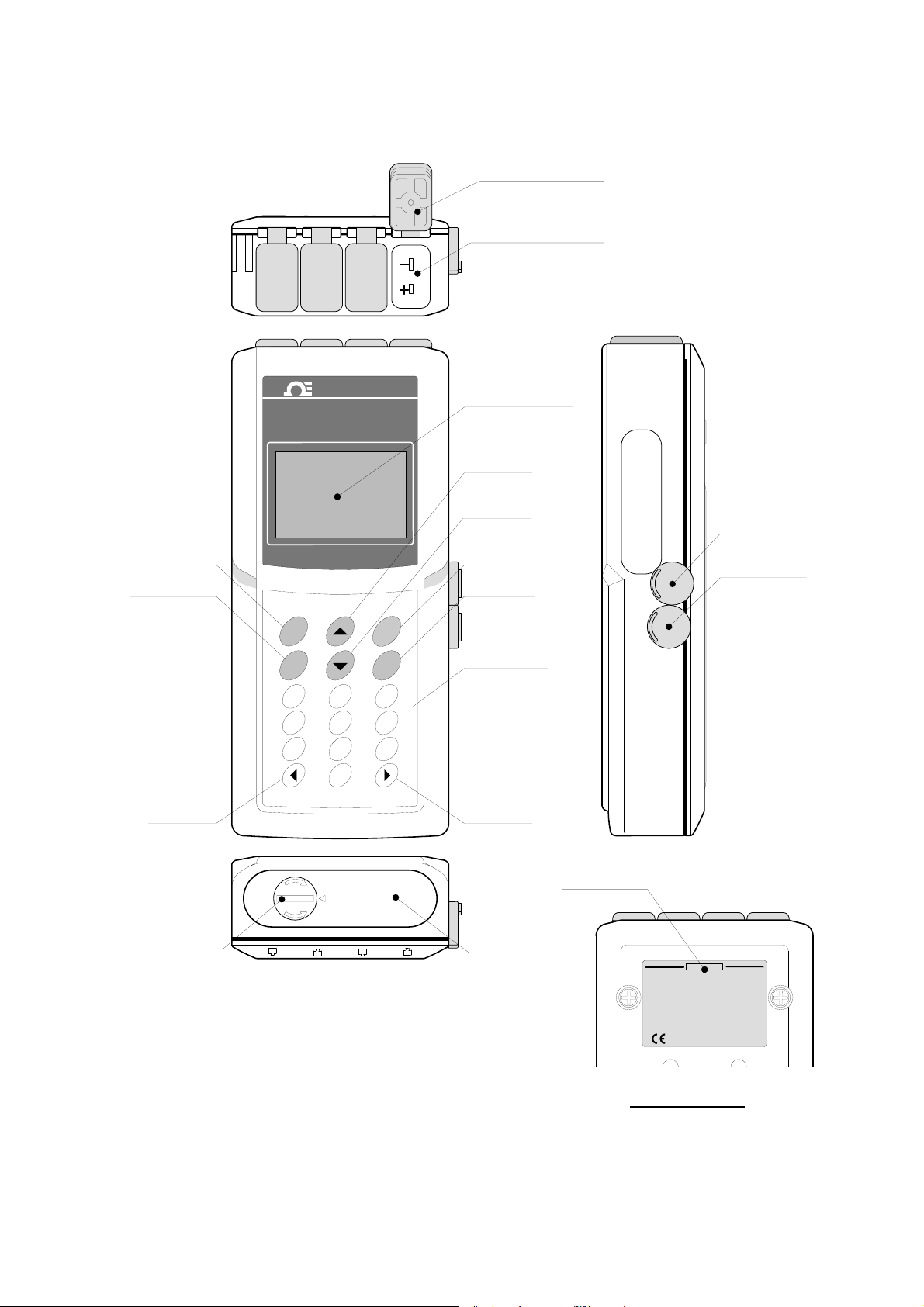
Part names
Enter key
Cancel key
Left key
Battery cover lock
ch.1
ch.2 ch.3
OMEGA
Handy- Logger OM-2041
ENT
Cancel
Stop
1
4
7
ch
GH
I
ch
PQ
RS
+/-
CLOSE
OPEN
Power
FUNC
AB
C
ch
2
3
JK
L
6
5
TU
V
8
9
0
SYMB
LOCK
ch.4
Clear
DE
F
MN
O
WX
YZ
Connector cover
Sensor port
Display panel
Up key
Down ke
Power key
Function key
Ten-key pad
Right key
CAUTION Sign
Battery cover
Communication
port
External power
supply
PC
DC IN
CAUTION!
Don't p ut any o ther thing without
●
specification into plugs.
instrument as any cap opens.
specified AC adaptor.
put impact on the instrument.
dry cells as t he c ompartment is dry, and
fastenthe lid tightly.
Please read instruction manual thoroughly
◎
thisinstrument.
Model:OM‑2041‑XX
Mfg.No:MR**Q***
Don't use this
●
●
Don't drop and don't
●
●
Use only
Exchange
Bottom surface
1
Page 8
B
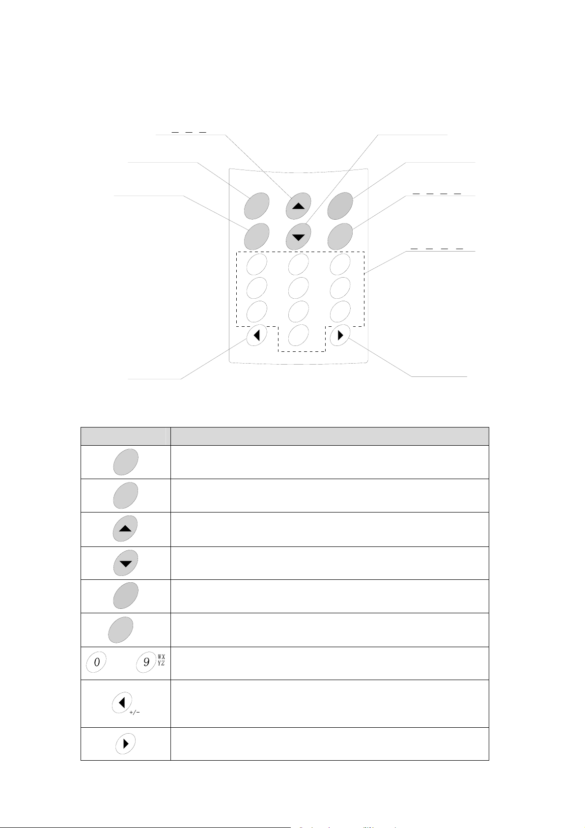
Key names and functions
[Key names]
Up key
Enter key
決定キー
Cancel key
戻るキー
Left key
左キー
上キー
ENT
Cancel
Stop
1
4
7
Down key
下キー
Power key
電源キー
Function key
機能キー
Power
FUNC
ch
GH
I
ch
PQ
RS
AB
ch
C
2
JK
L
5
TU
V
8
Clear
DE
F
3
MN
O
6
WX
9
YZ
Ten-key pad
テンキー
0
+/-
SYMB
Right key
右キー
[Key functions]
Key Function
ENT
Cancel
Stop
Power
FUNC
SYM
to
Clear
Setting and registration of the data and movement to the next screen
Start of the recording operation
Cancellation of each item and return to the previous screen
Stop of the recording operation
Up movement of the cursor
Backward movement of the recorded data in the successive order as checking data
Down movement of the cursor
Forward movement of the recorded data in the successive order as checking data
Turning(ON or OFF) of the power or display
Display of the main menu
Clearance of the character at the cursor position as inputting characters
Input of a numeric value or character
Change of the display mode (1, 2, 4)
Left movement of the cursor
Change of the display channel in the 1&2-channel display mode
Change to “−“ input as inputting numeric values
Right movement of the cursor
Change of the display channel in the 1&2-channel display mode
2
Page 9
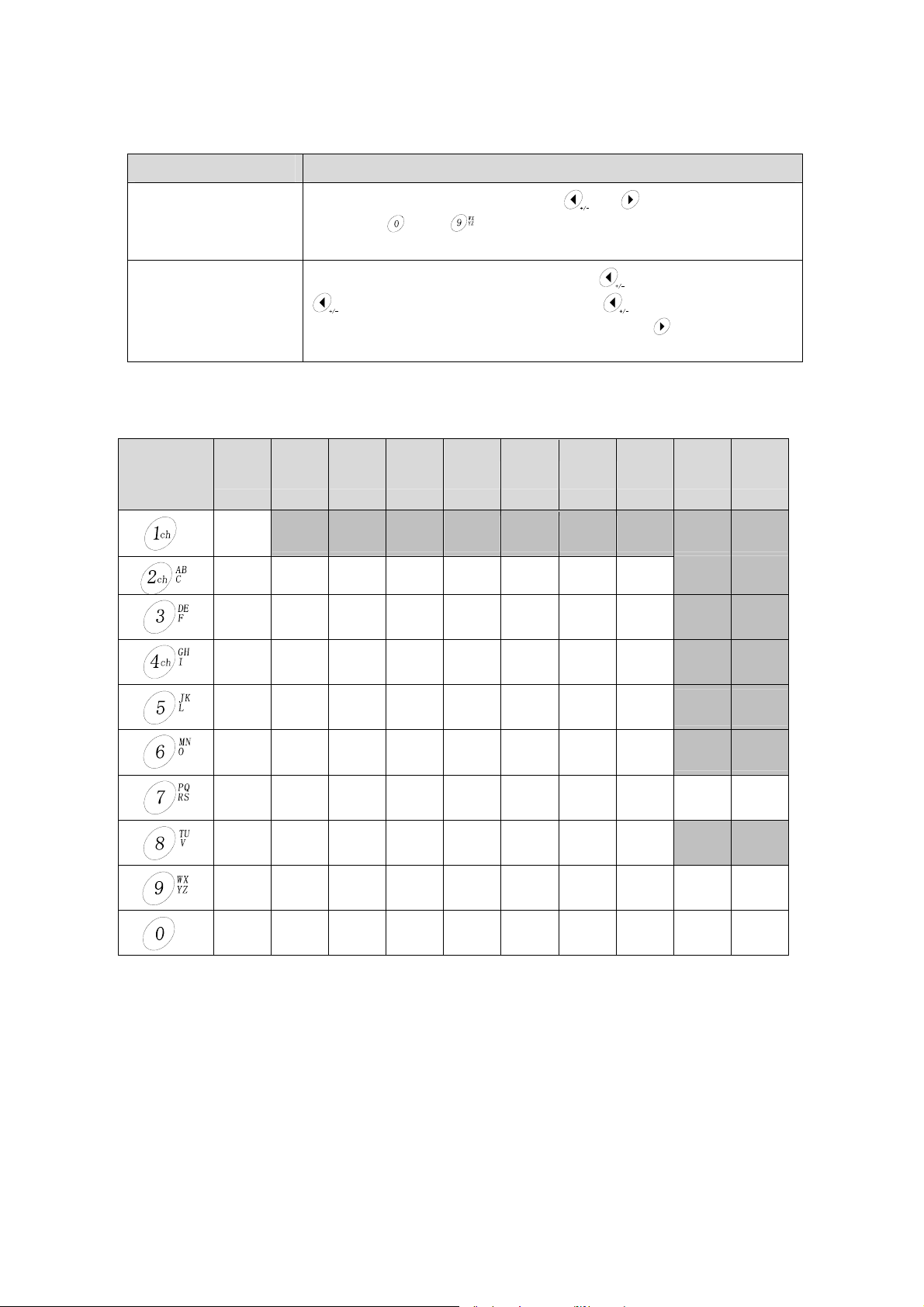
[How to input numeric values]
Input character Input method
Move the cursor to a position to be input by
“0” to “9”
“−“ (minus)
value using
value is input.
Move the cursor to the left end of the input line by
key to display “−“. Hereupon, as pressing key repeatedly, the display
is alternately switched between “−“and “ “ (blank). , press
cursor to the right to set “−” or “ “ (blank).
SYMB
to
[How to input alphanumeric characters]
The character is changed by the times of pressing ten-key.
Times of
pressing
the key
1 time 2 times 3 times 4 times 5 times 6 times 7 times 8 times 9 times 10 times
1
A B C 2 a b c 2
D E F 3 d e f 3
or key, and input a numeric
key. The cursor is moved to the right after a numeric
key, and then further press
key to move the
SYMB
G H I 4 g h i 4
J K L 5 j k l 5
M N O 6 m n o 6
P Q R S 7 p q r s 7
T
U
W X Y Z 9 w x y z 9
0 % ! ( ) 0 + - * /
V 8 t u v 8
3
Page 10
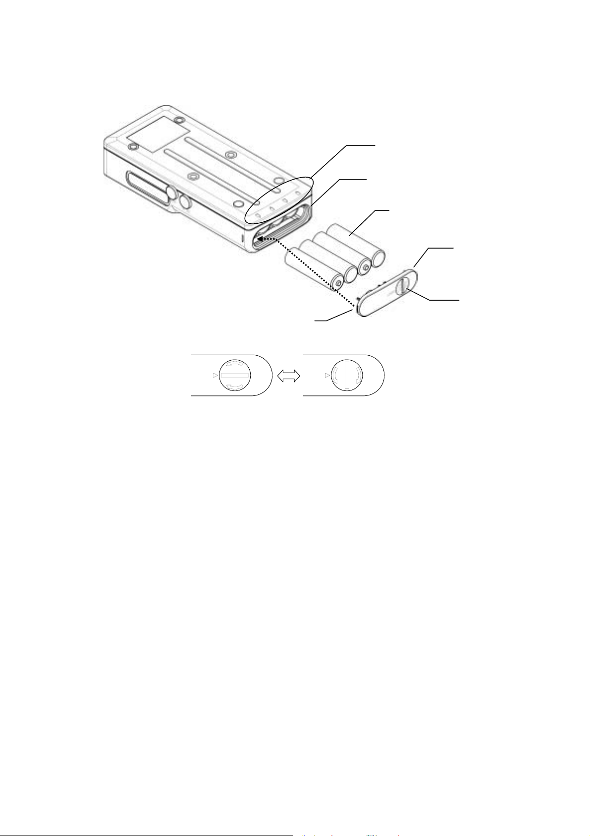
Mounting and replacement of the batteries
This unit is designed to be operated with four AA batteries.
Hinge
ロック状態
Lock Open
OPEN
LOCK
CLOSE
Battery cover lock
オープン状態
LOCK
Battery orientation
Battery port
AA batteries (4 pcs.)
Battery cover
Cover lock
OPEN
CLOSE
[Mounting the batteries]
c Switch off this unit.
d Turn the battery cover lock counterclockwise to put it in the open situation by a coin.
e Remove the battery cover to open the battery insertion port.
f The marking to show the battery orientation is provided at the lower portion on the bottom surface
of this unit. Insert four AA batteries properly according to this indication.
g Hang the hinge of the battery cover on the hinge support of this unit to mount the battery cover.
h Turn the battery cover lock clockwise to lock it by a coin.
If the external power supply (AC adaptor) is not connected, the unit starts immediately after replacing
the batteries.
CAUTION
• Do not use any battery other than the specified one. Otherwise, the unit may malfunction.
• If the battery cover is not closed completely, the water may enter or the cover may be opened when
a small shock is applied to the unit. Close the battery cover firmly to avoid such troubles.
Otherwise, the unit may malfunction.
• Replace all of four batteries by new ones.
4
Page 11
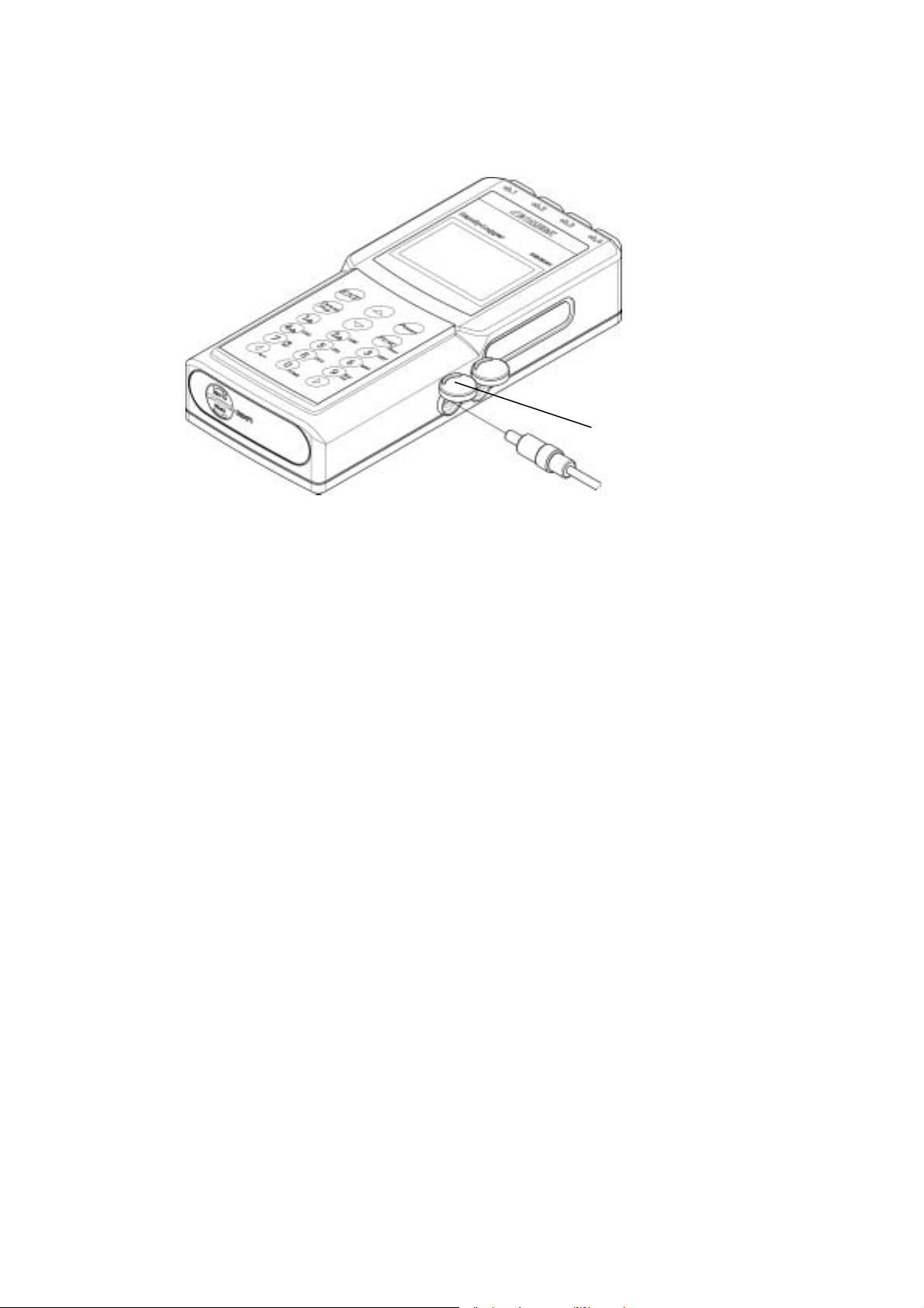
AC adaptor
The AC power can be supplied to this unit as connecting the accessory AC adaptor.
External power port (DC IN)
[Connecting the AC adaptor]
c Switch off this unit.
d Open the cover of the port, on which is marked with “DC IN”. (See the above Figure.)
e Insert the plug of the AC adaptor into the port completely until it is in contact with the far side.
f Insert the AC adaptor into an AC outlet.
Additionally, if the AC adaptor and batteries (AA batteries) are set at the same time, the power supply
from the AC adaptor takes the precedence over the batteries.
CAUTION
• Use only the AC adaptor supplied with this unit.
Do not use any AC adaptor other than the specified one. Otherwise, the unit may malfunction.
• Do not insert the AC adaptor into the communication port. Otherwise, the unit may malfunction.
• Insert the plug of the AC adaptor into the port of this unit firmly until it is in contact with the far
side.
• Hold the plug firmly and pull it out as disconnecting the AC adaptor.
If the lead cable is pulled to disconnect the AC adaptor, the unit may malfunction.
• The drip-proof performance cannot be maintained as using the AC adaptor.
• Close the cover firmly if the AC adaptor is not used.
Otherwise, the drip-proof performance may damage and the unit may malfunction.
[Batteries]
This unit can also be operated only with the AC adaptor. However, the batteries (four AA
batteries) should be mounted as power supply to backup data even if the AC adaptor is disconnected.
5
Page 12
Connecting the sensor
The following signal inputs are acceptable for this unit. These are the specified sensor with the special
drip-proof connector, current/voltage input adaptor, or the sensor with the miniature male
thermocouple connectors.
Sensor port
Sensor connector
Connector cover
Connector holder
◆ Special sensor
[Connecting the sensor]
c Switch off this unit.
d Open the connector cover of a desired channel to insert the sensor.
e Put the sensor connector in the sensor port as facing the connector holder toward the bottom surface
of the unit.
f Insert the sensor connector until the holder hook of the connector is locked with the main unit.
CAUTION
• Check the connector orientation carefully.
If the connector is inserted forcibly in the incorrect direction, the unit and/or sensor may be
damaged and may malfunction.
• Pay attention carefully enough not to peel off the connector packing when inserting the connector,.
If the connector packing is peeled off, the drip-proof performance cannot be maintained and the
unit may malfunction.
• Connect or disconnect with the sensor carefully enough not to break any sensor lead.
Otherwise, wiring trouble may occur and the unit may malfunction.
[Disconnecting the sensor]
c Switch off this unit.
d Hold the connector holder of the sensor and pull it out straight with the connector hook disengaged.
CAUTION
• Do not pull the lead cable when disconnecting the sensor. Otherwise, wiring trouble may occur and
the unit may malfunction.
• Close always the connector covers of the channels not in use. Otherwise, the drip-proof
performance may not to be maintained and the unit may malfunction.
6
Page 13

◆ Current/Voltage input adaptor
Flathead screwdriver
Polarity
Case screw *1
Terminal screw
Wire port
Lead wire
[Mounting and wiring]
c Switch off the unit.
d Mount the current/voltage adaptor on this unit. (See the section, Special sensor.)
e Loosen the terminal screw of the current/voltage adaptor to open the wire port.
f Insert the lead wire into the wire port.
g Tighten the terminal screw of the current/voltage adaptor and close the wire port.
CAUTION
• The drip-proof performance cannot be maintained while using the current/voltage adaptor.
• The following shows the lead wires, which is suitable for the current/voltage adaptor.
Solid wire: 0.14 to 1.5mm
Stranded wire: 0.14 to 1mm
2
2
/AWG26 to16
• Never loosen the case screw (phillips screw) (*1).
7
Page 14
−
(
+
)
◆ Sensor with thermocouple connector
Connector cover
Wide (
)
Miniature connector
Sensor port
Narrow
[Connection with the sensor]
c Switch off this unit.
d Open the connector cover of a channel to insert the sensor.
e Put the sensor connector in the sensor port while referring to the polarity (see the Fig.) marked on
the connector port of this unit.
f Insert the connector firmly until it is in contact with the far side.
CAUTION
• Check the connector orientation carefully.
If the connector is inserted forcibly in the incorrect direction, the unit and/or sensor may be
damaged and may malfunction.
• Connect or disconnect with the sensor carefully enough not to break any sensor lead.
Otherwise, wiring trouble may occur and the unit may malfunction.
[Disconnection with the sensor]
c Switch off this unit.
d Hold the sensor connector and pull it out straight.
CAUTION
• A general thermocouple connector on the market is available for the unit.
However, note that the thermocouple connector different from the specified sensor is not applicable
to the drip-proof structure.
• Do not hold the lead wire and pull it out when disconnecting the sensor.
Otherwise, wiring trouble may occur.
• Close always the connector covers of the channels not in use. Otherwise, the drip-proof
performance may not to be maintained and the unit may malfunction.
8
Page 15
(
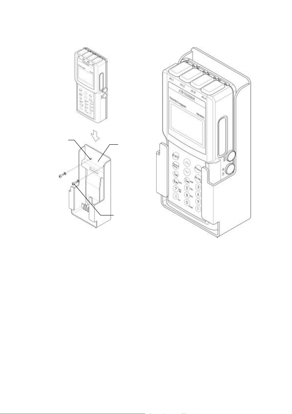
Mounting holder
Screw hole
2 locations)
Mounting
holder
Attached screws
and washers
[Installing the mounting holder]
c Fix the mounting holder at a desired position firmly using the attached screws and washers.
d Insert this unit from the top of the holder.
CAUTION
• The mounting holder installation conditions must conform to the storage conditions of this unit.
• Install the mounting holder vertically.
• Do not insert this unit reversely in the vertical or back and forth direction.
9
Page 16
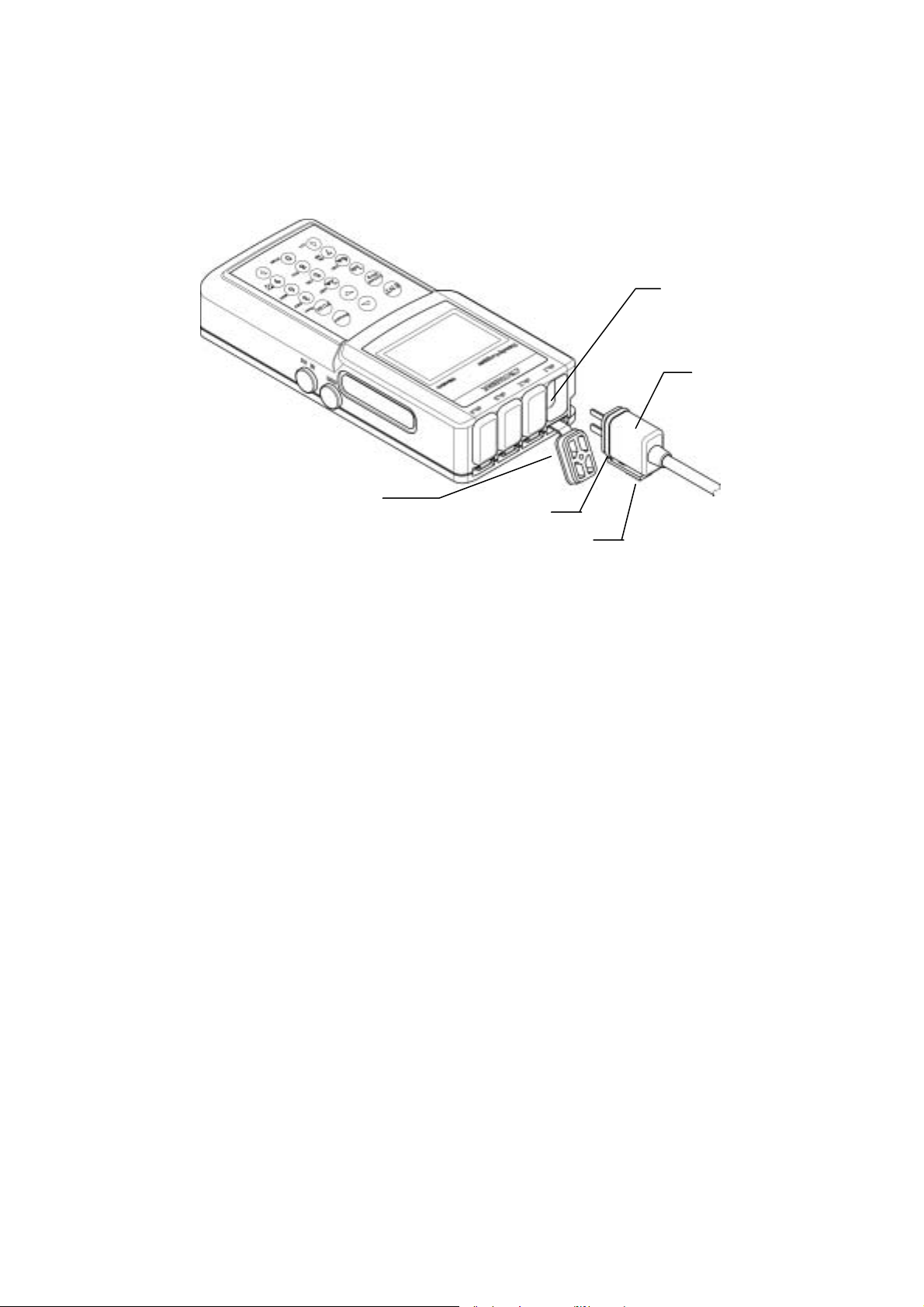
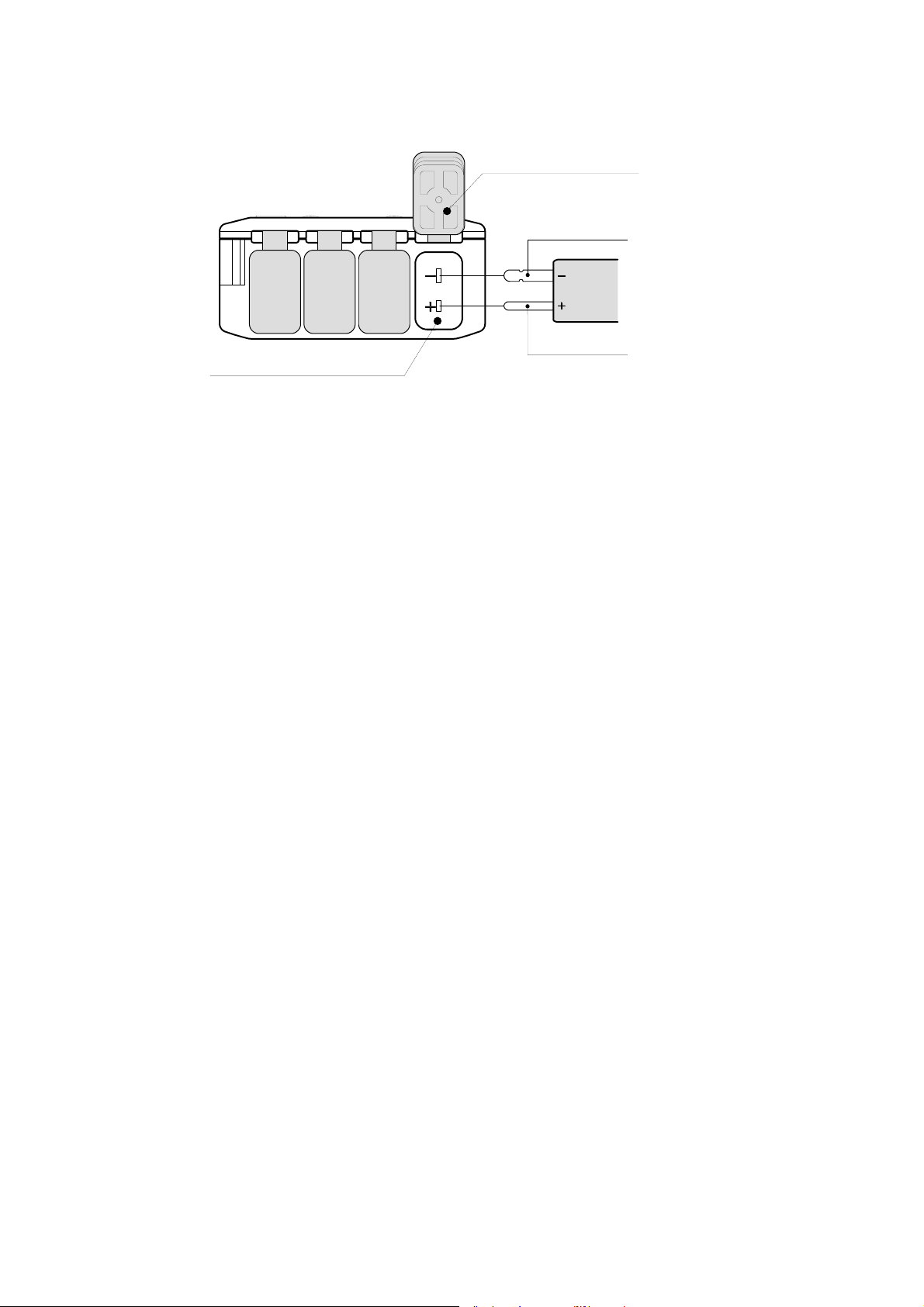
Battery replacement adaptor
The accessory DC adaptor can be used for continuous logging as replacing batteries. This unit
automatically operates on the back-up mode when the remaining battery level falls below the designed
voltage. In this case the batteries should be replaced immediately.
External power port
Communication port
Plug
Battery
[Connecting the DC adaptor]
c Connect the specified battery (006P/9V – 1604 or 6LR61, 6F22) to the snap.
d Open the cover of the port, on which is marked with “DC IN”. (See the above Figure.)
e Insert the plug of the DC adaptor to the port completely until it is contact with the far side.
The DC power supply is displayed with “External power icon” on the LCD.
f Replace the batteries according to the section “Mounting and replacement of the batteries”.
g Disconnect the DC adaptor finally.
CAUTION
• Do not use any battery other than the specified one. Otherwise, the unit may malfunction.
DC Adapter
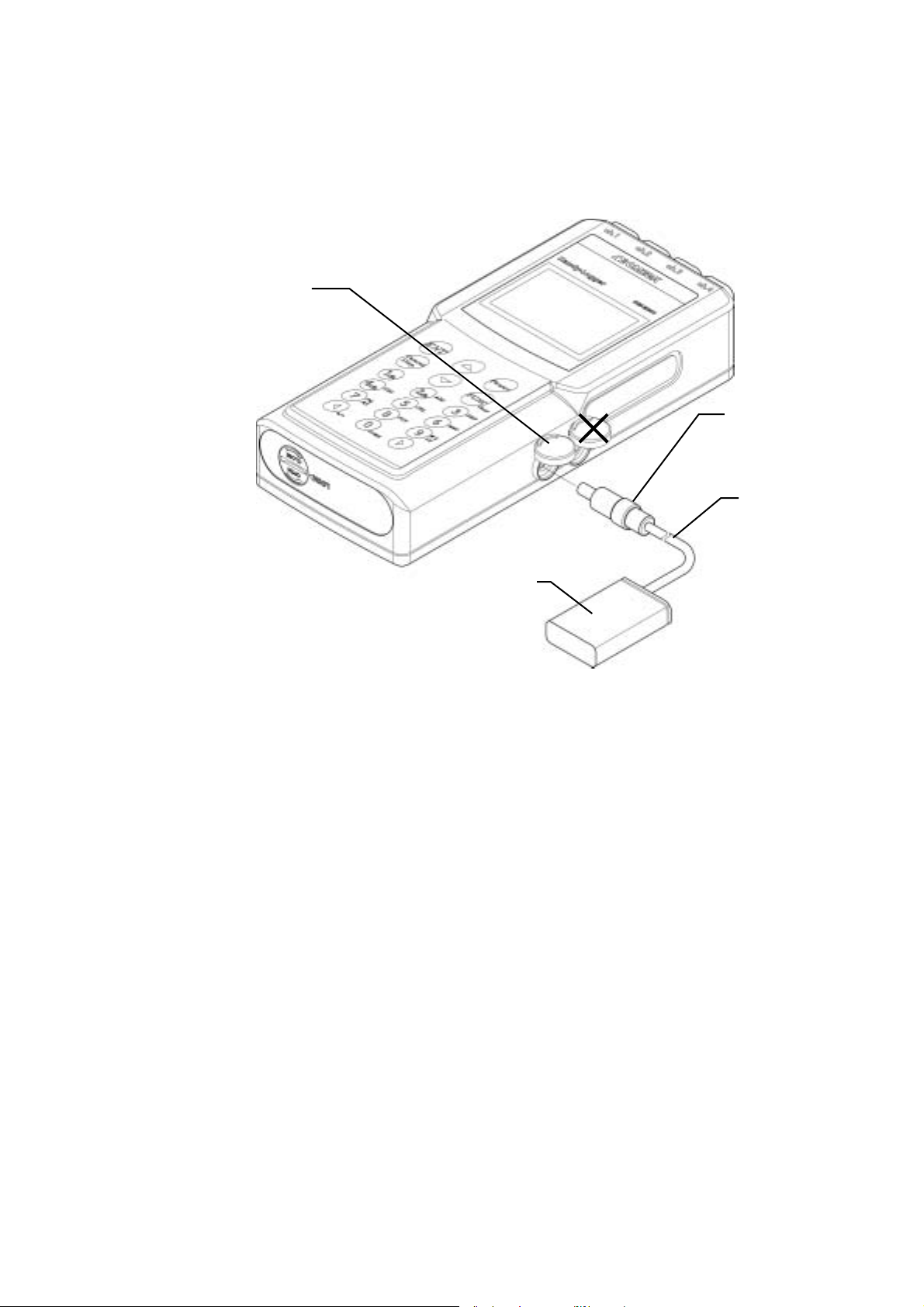
• Do not insert the DC adaptor to the communication port. Otherwise, the unit may malfunction.
• Inset the plug of the DC adaptor into the port of this unit firmly until it is in contact with the far
side.
• Hold the plug firmly and pull it out as disconnecting the DC adaptor. If the lead cable is pulled
to disconnect the DC adaptor, the unit may malfunction. Do not insert the DC adaptor to the
communication port. Otherwise, the unit may malfunction.
• Close the cover firmly when the DC adapter is not in use. Otherwise, the drip-proof
performance may damage and the unit may malfunction.
10
Page 17
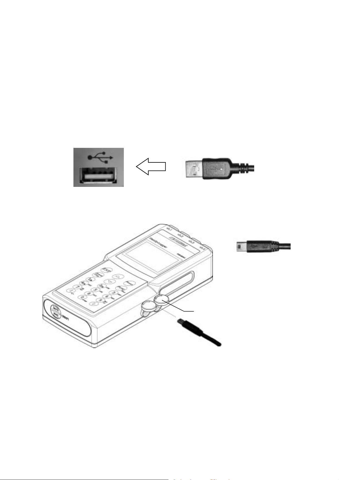
Connecting to your Personal Computer (USB)
When this unit is connected to your PC (personal computer) with the special USB cable, the recorded
data can be read and saved into a file on the PC. The setting of recording can be written from the PC
too. Also, the special USB cable (supplied with the optional software) is naturally required to
communication the date with the PC.
1 Connecting the special cable to this unit
[PC side] Connect the A connector of the USB cable to the USB port.
CAUTION
• Hold the plug of the cable and pull it out when disconnecting the cable connector.
• If the lead cable is pulled to disconnect the connector, the unit may malfunction.
USB port A connector
[Logger side] Connect the mini B connector of the USB cable to the communication port.
Mini B connector
Communication port
Open the cover of the communication port with the “PC” marking and insert the plug of the USB
cable firmly into the communication port until it is in contact with the far side. Also, use the special
cable supplied with the optional software.
CAUTION
• Hold the plug and pull it out when disconnecting the cable connector.
If the lead cable is pulled to disconnect the connector, the unit may malfunction.
• Use the special cable (supplied with the software) only.
• Close the cover firmly if the cable is not used.
Otherwise, the drip-proof performance may be damaged.
11
Page 18

Connecting to your Personal Computer (RS-232C)
When this unit is connected to your PC (personal computer) with the special cable (RS-232C),
the recorded data can be read and saved into a file on the PC. Also, the setting of recording can be
written from the PC.
This unit must be connected to the PC with the special cable to communicate the data with the unit
connected to the PC.
The special cable (supplied with the software) is absolutely required to communicate the data with the
PC, on which the optional data read software is installed.
1 Connecting the special cable to this unit
Communication port
[Connecting the special cable]
c Switch off this unit.
d Open the cover of the port with the “PC” marking.
e Insert the plug of the special cable firmly until it is in contact with the far side.
f Switch on this unit.
CAUTION
• Use the special cable supplied with the software. If any connection cable other than the specified
one is used, the unit may malfunction.
• Insert the plug of the special cable firmly into the communication port of the unit until it is in
contact with the far side.
Otherwise, incorrect communication may occur.
• The drip-proof performance cannot be maintained when the special cable is used.
• Hold the plug and pull it out when disconnecting the special cable.
If the lead cable is pulled to disconnect the connection cable, the unit may malfunction.
• Close the cover firmly if the cable is not used.
Otherwise, the drip-proof performance may be lost.
12
Page 19

2 Display the home screen and press
Select [Communication] by the [] or [] key.
3 Press
ENT
key.
FUNC
key.
Clear
(The screen is changed to the communication standby screen.)
Communicating
Perform the operation via the software. When the communication is started, the message,
“Communication”, will appear on the communicating screen.
⇒ Press [CANCEL] key to return from the communication standby screen to the previous screen.
See the instruction manual for software for further information on software operation.
13
Page 20

Backup Battery
A backup battery is built-into this unit in order to keep the data even if the power is not supplied from
the battery and/or external power supply. If the remaining battery level becomes insufficient, the
following message will appear.
Stop the operation and save the recorded data if this message screen appears.
Contact quickly your local sales representative or sales office to replace the built-in backup battery
(charge).
CAUTION
• If the batteries (four AA batteries) are replaced with this message indicated, the power is not
supplied to this unit as soon as any battery is removed. In this case, therefore, the power should
supply from the AC adaptor.
14
Page 21

Recording modes
This unit provides two kinds of recording modes, log mode and tag mode. You can select a desired
mode suitable for your application.
Log mode
In this mode, data is recorded at constant intervals (Intervals) from the date and time to start recording
to the one to end recording.
c Log settings (Interval, etc.)
d Personnel
e Comment
f Date and time to start/end recording
Recorded data 1 (CH1 to 4), with/without data mark
Recorded data 2 x
Recorded data 3 x
x
x
Recorded data n (CH1 to 4), with/without data mark
Log name
The following items shall be set before starting to record the data. Those are the preset items for each
log (c Log setting), items selected as the situation of the unit (d Working person and eRemark), and
items to be set for recording (f Date and time to start/end recording).
Setting location Setting item Contents
c Log setting Interval Intervals to record the measured value
Sensor type Type of the sensor to be connected to each channel
Unit Unit of indication as using the voltage/current input adaptor
Minimum value of
Maximum value of
Alarm value for upper limit Temperature designated as the upper limit
Alarm value for lower limit Temperature designated as the lower limit
Accumulation base Reference temperature to calculate the accumulation value
e /Comment
f Recording time Date and time to start Data and time to started the recording
Date and time to end Data and time to complete the recording
Input of “V”
Indication at the minimum(0V/0mA) by the voltage/current
scale
scale
Point position Number of digits below the decimal point at the minimum
Working person Name of working person to record data d Personnel
Comment Comment to be attached to the recorded data
input adaptor
Indication at the maximum value (5V/20mA)
by the voltage/current input adaptor
and maximum of scale
15
Page 22

Tag mode
In this mode, data is recorded every time the key is operated (trigger is activated), and then recorded
data is added to the data.
c Tag settings
Recorded data 1 (CH1 to 4), d Personnel, e Comment, date and time of recording
Recorded data 2 (CH1 to 4), d Personnel, e Comment, date and time of recording
x
x
x
Recorded data n (CH1 to 4), d Personnel, e Comment, date and time of recording
The following items shall be set before staring to record the data .Those are the preset items for each
tag (c Tag settings) and items selected as the situation of the unit (d Personnel and eComment).
Setting location Setting item Contents
c Tag setting Sensor type Type of the sensor to be connected to each channel
Unit Unit of indication as using the voltage/current input adaptor
Minimum value of
Maximum value of
Alarm value for upper limit Temperature designated as the upper limit
Alarm value for lower limit Temperature designated as the lower limit
e /Comment
Input is “V”
Indication at the minimum value (0V/0mA)
scale
scale
Period position Number of digits below the decimal point at the minimum
Working person Name of working person to record data d Personnel
Comment Comment to be attached to the recorded data
by the voltage/current input adaptor
Indication at the maximum value (5V/20mA)
by the voltage/current input adaptor
and maximum of scale
16
Page 23

Change of the Recording Mode
The recording mode is changed with the key operation while starting up.
1 Press
Stop recording if the unit is currently recording the data.
2 Press
Power
key to turn OFF the power.
Power
key with
Cancel
Stop
key kept pressed.
(The screen is changed to the confirmation screen of the recording mode.)
Select [Yes] by the [<] or [>] key, and then press [ENT] key.
When [No] is selected, the operation is started up without changing of the mode. (Normal startup)
The operation is started up with the mode changed (log mode to tag mode or tag mode to log mode).
The home screen will appear.
CAUTION
• When the mode is changed, the recorded data and the setting in the previous mode are cleared
completely.
Therefore, please be sure to save the data before changing the mode.
17
Page 24

Operation Flow (Log Mode)
POWER ON
HOME
FUNC
Main menu
LOGging No.
Settings
ENT
RecordingTime
ENT
LOGging No.
Settings
FUNC
Timer set Standby
ENTFUNC
ENT
FUNC
ENT FUNC
Data check
(1/2 /4c h d isp.)
(Alarm)
(Max./Min./Ave)
(CH average)
(Accumulate value)
Settings
(Se ns or ty pe )
(Interval)
(Alarm)
(Accum.base)
Delete settings
Recording
Unit/Scaling
Personnel
/Remark
Communication
Other settings
Personnel/Remark
Personnel select
Remark select
Comm.Standby
Other Settings
Memory/Battery
Backlight/Sound
Auto power off
Temp.shift
LCD contrast
Clock settings
Instrument name
Default settings
Personnel
Remark
communication
Memory/Battery
Backlight/Sound
Auto power off
Temperature shift
LCD Contrast
Clock Settings
Instrument name
D efa u lt settin gs
(Se ns or typ e)
(Interval)
(Alarm)
(Accum.base)
FUNC
FUNC
FUNC
Add name
Add remark
Unit/Scaling
All LOG delete
Initialize
゚C<->゚F Temperature unit
All LOG delete
Initialize
18
Page 25

Operation Flow (Tag Mode)
POWER ON
HOME
FUNC
Main menu
TAGged No.
Settings
Personnel
/Remark
ENT
Standby Recording
ENT
ENT
TAGged No.
Settings
FUNC
Personnel/Remark
Personnel select
FUNC
ENT FUNC
(1/2 /4ch d is p.)
(Max./Min./Ave)
(CH average)
(Se ns or ty pe )
Delete settings
Data check
(Alarm)
S ettin gs
(Alarm)
Personnel
FUNC
Unit/Scaling
Add name
Communication
Other settings Other Setti ngs
Comm.Standby
Instrument name
Remark select
Memory/Battery
Backlight/Sound
Auto power off
Temp.shift
LCD contrast
Clock settings
Default settings
All TAG delete
Initialize
Remark
communication
Memory/Battery
Backlight/Sound
Auto power off
Temperature shift
LCD Contrast
Clock Settings
Instrument name
D efa u lt se tting s
(Se ns or typ e)
(Alarm)
All TAG delete
Initialize
FUNC
FUNC
Add remark
Unit/Scaling
゚C<->゚F Temperature unit
19
Page 26

Starting up (Home Screen)
This section describes the home screen that appears when the power is turned ON and when the unit is
started up.
1 Press
Power
key to turn ON the power.
The home screen appears on the LCD panel.
On the home screen, the current value of each channel is updated at intervals of 1 sec. The currently
selected log (tag) No. is shown at the upper left portion of the screen.
Additionally, the current date and time are shown at the lower portion of the screen.
The home screen provides three kinds of display modes depending on the channel number to display
on it. This display mode can be changed by the one-touch operation.
Icon indication
アイコン表示
Log No.
ログ番号
Available
memory
capacity
メモリ残量
現在値
Current value
1-channel display
1チャンネル表示
[1] key
「1」キー
Current date and time
現在日時
2-channel display
2チャンネル表示
[2] key
「2」キー
Sensor type
入力種類
4-channel display
4チャンネル表示
[4] key
「4」キー
Change the display channel by the [<] or [>] key in the 1-channel and 2-channel display modes.
Key 1-channel display 2-channel display
>
<
CH1→CH2→CH3→CH4→CH1…
CH1/2→CH3/4→CH1/2…
CH1→CH4→CH3→CH2→CH1…
20
Page 27

[Available memory]
The remaining capacity of the memory, into which the data is recorded, is indicated by the bar graph
(50 steps). The number of data to be recorded to this unit may vary depending on the recording mode,
that is, log mode or tag mode.
メモリ残量
Remaining capacity
100%
100%
メモリ残量
Remaining capacity
50%
50%
メモリ残量
Remaining capacity
0%
0%
z Log mode
In the log mode, the data can be recorded until the total number of data recorded to 20 logs reaches
40000.
One number of data corresponds to the data volume used for one recording at one channel.
Therefore, the number of data to be recorded may vary depending on the number of channels to be
used.
The available recording cycles is calculated from the following formula.
Available recording cycles [cycles] = Free memory capacity [data] ÷ Number of channels in use
[ch]
The available recording time is calculated from the following formula.
Available recording time [time] = Number of remaining cycles [cycles] × Recording interval
[time]
[Example]
If the free memory capacity is “1000”, all of four channels are used, and data is recorded at intervals of
5 min., the available recording time is 1250 min.
1000 (free memory capacity) ÷ 4ch (number of channels in use) × 5 min. (recording interval) = 1250
[min]
z Tag mode
In the tag mode, the data can be recorded until the total number of data recorded to 20 tags reaches
10000.
One number of data corresponds to the data volume used for one recording at one channel.
However, the number of data to be consumed may vary depending on the number of channels in use.
Number of channels in use Calculation formula of remaining recording cycle
1
2
3
4
[Example]
If the free remainder of memory capacity is “1000” and the data is recorded using three channels, up to
647 data records can be recorded.
1000 (free memory capacity) × 11÷17 (coefficient) = 647 [data]
Available recording cycles = Free memory capacity [data] ×11÷11
Available recording cycles = Free memory capacity [data] ×11÷14
Available recording cycles = Free memory capacity [data] ×11÷17
Available recording cycles = Free memory capacity [data] ×11÷20
21
Page 28

[Sensor types]
The currently selected input type of each channel is indicated. In the unit, “K”, “T”, “E”, or “J” type
thermocouple are available.
Additionally, when using the optional voltage/current adaptor (sold separately), it is also available for
the DC voltage or DC current signals.
Symbol K T E J V
Input type “K” thermocouple “T” thermocouple “E” thermocouple “J” thermocouple
Voltage/Current
adaptor
z Voltage/Current signal input
In this unit, , the DC voltage (0 to 5V) or DC current (0 to 20mA) signals can be measured as using the
optional adaptor of voltage or current input.
When [V] is selected for the input, the unit and scale can be set.
Item Setting range Remarks
Unit Up to three characters Alphanumeric characters
−9999 to 9999
−9999 to 9999
Fraction part 0 to 3 Number of digits below decimal point 0:0, 1:0.0, 2:0.00, 3:0.000
CAUTION
Voltage Indication at 0V of the input Min. scale
Current Indication equivalent to 0 mA of the input( calculated) Indication
span of this unit ÷ output span of the input × (−4mA)
Voltage Indication at 5Vof the input Max. scale
Current Indication at 20mA of the input
−
No connection
• If “−“ (no connection) is set for all channels, the data cannot be recorded.
[Icon indication]
Icons are indicated at the upper right portion of the screen to show various situations.
c Battery level
The remaining of battery capacity is always indicated by the battery icon. The remaining capacity
is indicated in three steps. Replace the batteries with new ones before recording data for a long
time if the remaining capacity becomes 25% or less (icon is flashing).
点滅:
消灯:
Off: Remaining capacity
残量75%以上
is 75% or more.
点灯:
Lit: Remaining
残量50%
capacity is 50%.
d External power supply
The icon for external power supply is indicated as using the AC adaptor.
Flashing: Remaining
capacity is 25% or less.
残量25%以下
Icon for external power
supply
外部電源表示
22
Page 29

e Key lock
When
[CANCEL] key and [] key are pressed at the
same time on the home screen, this unit enters the key
lock state and the icon shown in the right figure is lit.
When the key lock function is activated, no function
keys are accepted.
Therefore, only “recording” and “remaining capacity/
check of unit name” can be operated.
Press
[CANCEL] key and [] key again at the same
time to cancel the key lock.
Key lock icon
キーロック表示
f Data mark
Data mark icon
データマーク表示
In the log mode, the mark is able to be put on the
recorded data.
The data mark icon is lit when the mark is put on the
recorded data or the marked data is shown on the data
check screen.
Check of remaining capacity/ unit name
When pressing the [] key while the home screen is being displayed, the battery level and instrument
name can be checked.
⇒ Press [CANCEL] key to return to the home screen.
2 Keep
Power
key pressed for 3 sec. or longer to turn OFF the power.
23
Page 30

Various settings
The mode has to be changed to the “other settings” mode to change or initialize the settings.
1 Display the home screen.
ログ番号
Log No.
Available of memory
capacity
メモリ残量
現在値
Current value
Current date and time
現在日時
2 Press
Select [Other settings] by the [] or [] key.
3 Press
FUNC
key. (The screen is changed to the main menu screen.)
Clear
ENT
key. (The screen is changed to the screen of other settings.)
24
Page 31

Select a setting item to set up by the [] or [] key. Various settings can be performed as pressing
[ENT] key.
The following Table describes various setting items.
Item Function
Memory/Battery Available memory capacity, battery level and the instrument name are indicated
Backlight/Sound ON/OFF settings of the LCD backlight , sound key , and alarm buzzer
Auto power off Setting of waiting time for the auto power off
Temp. shift Setting of offset for measured data
LCD contrast Adjustment of the contrast of LCD panel
Clock settings Setting of date and time
Instrument name Setting of unit name (up to eight characters)
Default settings The default settings of recording or the deletion
All LOG delete Simultaneous deletion of all log settings and data
Initialize Initialization of all settings to the factory default settings
°C<->°F
Change of temperature unit
25
Page 32

1. Checking the remaining memory/battery capacities
The remaining memory/battery capacities and the instrument name can be checked.
1-1 Display the home screen and press
1-2 Select [Other settings] and press
1-3 Select [Memory/Battery] and press
FUNC
key.
Clear
ENT
key.
ENT
key.
Available battery
capacity
バッテリ残量表示
75%
50%
25%
[Available memory capacity]
The number of data to be recorded into this unit may vary depending on the recording mode, that is,
log mode or tag mode.
z Log mode
In the log mode, the data can be recorded until the total number of data recorded to 20 logs becomes
40000.
One number of data corresponds to the data volume used for one recording at one channel.
Therefore, the number of data to be recorded may vary depending on the number of channels to be
used.
The available recording cycles is calculated from the following formula.
Available recording cycles [cycles] = Free memory capacity [data] ÷ Number of channels in use
[ch]
The available recording time is calculated from the following formula.
Available recording time [time] = Number of remaining cycles [cycles] × Recording interval
[time]
[Example]
If the free memory capacity is “1000”, all of four channels are used, and data is recorded at intervals of
5 min., the available recording time is 1250 min.
1000 (free memory capacity) ÷ 4ch (number of channels in use) × 5 min. (recording interval) = 1250
[min]
26
Page 33

z Tag mode
In the tag mode, the data can be recorded until the total number of data recorded to 20 tags becomes
10000.
One number of data corresponds to the data volume used for one recording at one channel.
However, the number of data to be consumed may vary depending on the number of channels in use.
Number of channels in use Remaining recording cycle calculation formula
1
2
3
4
Available recording cycles = Free memory capacity [data] ×11÷11
Available recording cycles = Free memory capacity [data] ×11÷14
Available recording cycles = Free memory capacity [data] ×11÷17
Available recording cycles = Free memory capacity [data] ×11÷20
[Example]
If the free remainder of memory capacity is “1000” and the data is recorded using three channels, up to
647 data records can be recorded.
1000 (free memory capacity) × 11÷17 (coefficient) = 647 [data]
[Battery level]
The remaining of battery capacity is indicated in four steps. Replace the batteries with new ones before
recording data if the remaining capacity becomes 25% or less.
27
Page 34

2. ON/OFF settings of the backlight/sound
Log mode Tag mode
The ON/OFF of backlight, sound key and alarm buzzer can be set.
ENT
FUNC
Clear
key.
ENT
key.
key.
2-1 Display the home screen and press
2-2 Select [Other settings] and press
2-3 Select [Backlight/Sound] and press
The ON/OFF of the backlight, key operation sound, and alarm buzzer can be set.
Select a setting item from various setting items by the [] or [] key and change the ON/OFF setting
by the [<] or [>] key.
When the unit is operated by the batteries, it is recommended to set all items to “OFF” in order to
extend the battery service life.
Item ON OFF
Backlight Lighting up of the backlight as turning ON of the display Non backlight
Key sound A beep sound as pressing a key Non beep sound
Alarm Continuous alarm sound on the H or L alarm Non alarm sound
⇒ Press [CANCEL] key to return to the previous screen.
2-4 Press
ENT
key to set the settings.
28
Page 35

3. Setting of the auto- power -off
In this unit, a period of time for the auto- power- off can be set. The unit automatically turns OFF the
power and display when this set time elapses from the last key operation.
ENT
ENT
FUNC
Clear
key.
key.
key.
3-1 Display the home screen and press
3-2 Select [Other settings] and press
3-3 Select [Auto power off] and press
Log mode
Tag mode
Select a period of time by the [] or [] key.
In addition to 1 min., 5 min., and 10 min. settings, the continuous operation mode is provided, in which
the auto- power- off is not activated.
Keep the [POWER] key pressed for 3 sec. or longer to power OFF the unit regardless of any setting.
⇒ Press [CANCEL] key to return to the previous screen.
CAUTION
• The auto-power-off is not activated in the communication mode.
3-4 Press
ENT
key to set the settings.
29
Page 36

4. Setting of offset values
In this unit, an offset value can be set for shift adjustment of the actual measured data from each
channel.
4-1 Display the home screen and press
4-2 Select [Other settings] and press
4-3 Select [Temperature shift] and press
FUNC
key.
Clear
ENT
key.
ENT
key.
Offset temperature of each channel
各チャンネルのオフセット温度
Current data adjusted with offset
設定後の測定値
Log mode
Tag mode
The measured data of each channel can be adjusted in steps of 0.1°C within a range of ±20°C.
Select a desired channel by the [] or [] key, and then input a numeric value by the ten-key pad or
the [<] or [>] key.
The adjusted current data is shown in [ ] on the right.
⇒ Press [CANCEL] key to return to the previous screen.
4-4 Press
ENT
key to set the settings.
CAUTION
• This offset affects the recording data or display data only when the input signal type is “K”, “T”,
“E”, or “J”. However, the offset does not affect the data, which has already been recorded.
30
Page 37

5. Adjustment of the contrast of LCD
The display contrast of the LCD can be adjusted.
ENT
ENT
FUNC
Clear
key.
key.
key.
5-1 Display the home screen and press
5-2 Select [Other settings] and press
5-3 Select [LCD contrast] and press
The screen contrast can be changed by the [<] or [>] key. Adjust the contrast in proper conditions.
Log mode
Tag mode
⇒ Press [CANCEL] key to return to the previous screen.
CAUTION
• If the contrast is set to a low level, the screen becomes difficult to read.
5-4 Press
ENT
key to set the settings.
31
Page 38

year
6. Setting of the date and time
Log mode
Tag mode
The clock inside this unit is set.
ENT
ENT
FUNC
Clear
key.
key.
key.
Date
日付
6-1 Display the home screen and press
6-2 Select [Other settings] and press
6-3 Select [Clock settings] and press
Time
時刻
Select the date or time by the [] or [] key, and then input the date or time by the ten-key pad or the
[<] or [>] key.
The date and time are set with 2-digit numeric value as shown in the following example.
Input example)
Date: 0 2 / 0 3 / 1 2
Lower 2-digit value
of Christian
Time: 1 2
Time (24-hour system)
Month
: 3 4: 5 6
Minute Second
Day
⇒ Press [CANCEL] key to return to the previous screen.
CAUTION
• If any invalid date and/or time are input, they are corrected automatically. Therefore, press [ENT]
key after checking the date and time to input.
6-4 Press
ENT
key to set the settings.
32
Page 39

7. Setting of an instrument name
An instrument name can be set. The name up to eight characters can be input.
ENT
FUNC
Clear
key.
ENT
key.
key.
Character input
英字/カナ切替え表示
7-1 Display the home screen and press
7-2 Select [Other settings] and press
7-3 Select [Instrument name] and press
機器名称
Instrument name
Input an instrument name by the ten-key pad or the [<] or [>] key.
Log mode
Tag mode
The name up to eight characters can be input.
⇒ Press [CANCEL] key to return to the previous screen.
7-4 Press
ENT
key to set the settings.
33
Page 40

8. Default settings of recording
The default settings are set. The default settings are convenient for the settings of recording which is
different from the initial settings (factory default settings) and may be used frequently, for example the
input types.
This setting is made in the same manner as described for section 5, Setting for the recording.
8-1 Display the home screen and press
8-2 Select [Other settings] and press
8-3 Select [Default settings] and press
(The screen is changed to the setting screen of sensor type)
Log No.
ログ番号
FUNC
key.
Clear
ENT
key.
ENT
key.
Sensor type of each channel
各チャンネルの入力種類
Log mode
Log mode
Tag mode
Tag mode
In this unit, the “K”, “T”, “E”, or “J” type thermocouple are available.
Additionally, when using the optional voltage input adaptor or current input adaptor (sold separately),
it is available for DC voltage (0 to 5V) or DC current (0 to 20 mA) signals.
Move the cursor to a channel to set by the [] or [] key, and change the input type by the [<] or [>]
key.
Symbol K T E J V
Input type “K” thermocouple “T” thermocouple “E” thermocouple “J” thermocouple
⇒ Press [CANCEL] key to return to the previous screen.
CAUTION
• When the input signal type is set to “V”, the unit and scale can be set.
• If “−“ (no connection) is set for all channels, the data cannot be recorded.
Voltage/Current
adaptor
−
No
connection
34
Page 41

8-4 Press
(The screen is changed to the setting screen of interval.)
Log No.
ログ番号
ENT
key to set the settings.
Interval time
インターバル時間
Interval time range
インターバル時間範囲
Log mode
Input a numeric value by the [<] or [>] key, or the ten-key pad.
The step of the interval setting is set to 1 sec. when the interval is from 1 sec. to 30 sec. and to 1 min.
when it is from 1 min. to 24 hrs.
⇒ Press [CANCEL] key to return to the previous screen.
CAUTION
• If any interval beyond setting range is input, this interval is not set even though [ENT] key is
pressed, and then it is automatically corrected to an acceptable setting value. Therefore, press
[ENT] key after checking or correcting the value to input.
• This setting is not provided in the tag mode.
35
Page 42

8-5 Press
ENT
key to set the settings.
(The screen is changed to the setting screen of alarm temperature for upper and lower limit.)
Log No.
ログ番号
各チャンネルの下限警報温度
Alarm temperature for lower limit of each channel
Alarm temperature for upper limit of each channel
Log mode
上限警報温度
Each one of alarm temperature for upper and lower limit can be set for each channel. The alarm is
given if the recorded data becomes higher than the alarm temperature for upper limit (H alarm) or
lower than the alarm temperature for lower limit (L alarm). The alarm sound can also be given during
recording data.
Move the cursor to a channel and the upper / lower limit by the [] or [] key. Then, set an alarm
temperature by the [<] or [>] key, or the ten-key pad.
The settable temperature may vary depending on the input type.
Tag mode
Input type Alarm setting range
K
T
E
J
−200.0 to 1370.0°C
−200.0 to 400.0°C
−200.0 to 700.0°C
−200.0 to 700.0°C
⇒ Press [CANCEL] key to return to the previous screen.
CAUTION
• The setting is not available if the input signal type is “V”. The setting is not available for a
channel, which has not been selected.
36
Page 43

8-6 Press
ENT
key to set the settings.
(The screen is changed to the setting screen of reference temperature for accumulation.)
Reference temperature for
accumulation of each channel
Log No.
ログ番号
各チャンネルの積算基準温度
The successive accumulation value (unit: °Ch) of the
difference between the recorded temperature and reference
temperature for accumulation is displayed. (For details,
see the Fig. on the right.)
However, note that the value recorded last is not included.
There are two kinds of accumulation values, H
accumulation that accumulates the difference higher than
the reference temperature for accumulation and L
accumulation that accumulates the difference lower than
the reference temperature for accumulation.
Move the cursor to a channel and reference temperature for accumulation by the [] or [] key.
Then, set the reference temperature by the [<] or [>] key, or the ten-key pad.
The settable temperature may vary depending on the input type.
Sensor type of each
各チャンネルの入力種類
Temperature
温度
収録開始 収録終了
Recording start
H accumulation value
H積算値
収録インターバル
Recording interval
Log mode
測定値
Measured value
L accumulation value
L積算値
Accumulation
積算基準値
reference value
Recording end
Time
時間
Input type setting range of reference temperature for accumulation
K
T
E
J
−200.0 to 1370.0°C
−200.0 to 400.0°C
−200.0 to 700.0°C
−200.0 to 700.0°C
⇒ To return to the previous screen, press [CANCEL] key.
CAUTION
• The setting is not available if the input signal type is “V”. The setting is available for a channel,
which has not been selected.
• This setting is not provided in the tag mode.
37
Page 44

8-7 Press
ENT
key to set the settings.
(The screen is changed to the confirmation screen of all default settings.)
Log No.
Select [Yes] by the [<] or [>] key on the conformation screen of writing.
CAUTION
• The confirmation screen of writing cannot be returned to the previous screen even though
[CANCEL] key is pressed.
Log mode
Tag mode
8-8 Press
ENT
key to register each setting as the default.
(The screen is returned to the home screen.)
CAUTION
• Move the cursor to [No] by the [<] or [>] key and press [ENT] key. The screen is then returned to
the screen of log (tag) selection without changing of settings.
38
Page 45

◆ Setting of the unit/scale
When the input type is set at “V”, the unit and scale can be set.
c Select [V] for the input type and press
(The screen is changed to the screen of scale/unit setting.)
Log No.
Number of digits
after decimal point
FUNC
Clear
key.
Log mode
Unit
Minimum scale value
Maximum scale value
Tag mode
Channel No.
Character input
Move the cursor to a setting item by the [] or [] key and input the unit (up to three characters),
maximum scale value, minimum scale value, and the number of digits after the decimal point.
Input a numeric value or character by the ten-key pad or the [<] or [>] key.
Item Setting range Remarks
Unit Up to three characters Alphanumeric characters (Character input: Aa)
−9999 to 9999
Voltage Indication at 0V of the input Min. scale
Current Indication equivalent to of 0 mA of the input (calculated)
−9999 to 9999
Fraction part 0 to 3 Number of digits below decimal point 0:0, 1:0.0, 2:0.00, 3:0.000
Voltage Indication at 5V of the input Max. scale
Current Indication at 20mA of the input
[Scaling]
For example, when connecting a unit having an
external output of 4 to 20 mA using an indication
scale of 0.0 to 100.0 %rh., make the settings as
shown in the Table on the right.
An input of 4 to 20mA is shown as “0.0 to
100.0%rh”.
⇒ Press [CANCEL] key to return to the previous
screen.
d Press
ENT
CAUTION
key to set the settings.
Indication span of this unit ÷ output span of the input ×(−4mA)
Item Set value Remarks
Unit ”%rh”
Scale Min.
Scale Max. “100” Indication at 20mA of the input
Decimal point “1” 1 digit below the decimal point
“−25” (100−0)÷(20−4)×(−4)=−25
• Even though the default setting is changed as having logs (tags) with the recording setting or
recorded data, the changed setting can not be accepted.
Save all logs (tags) and delete them at first to make the changed default setting acceptable.
39
Page 46

9. Deletion of all logs (tags)
All of log data with recorded data are deleted.
ENT
ENT
FUNC
Clear
key.
key.
key.
9-1 Display the home screen and press
9-2 Select [Other settings] and press
9-3 Select [All LOG delete] and press
Move the cursor to [Yes] by the [<] or [>] key on the confirmation screen of deletion.
Log mode
Tag mode
⇒ Press [CANCEL] key to return to the previous screen.
9-4 Press
CAUTION
• When this operation is run, all of recorded setting and data are deleted completely. Before running
• When [No] is selected on the confirmation screen of deletion and [ENT] key is pressed, the screen
ENT
key to delete all logs.
this operation, read the data and save it into a file.
is returned to the screen of other settings without change of settings.
40
Page 47

10. Initialization of the settings
The recorded setting and data are deleted completely and all settings are initialized to the default
settings made before shipment from the factory.
10-1 Display the home screen and press
10-2 Select [Other settings] and press
10-3 Select [Initialize] and press
ENT
FUNC
ENT
key.
key.
Clear
key.
Log mode
Tag mode
Move the cursor to [Yes] by the [<] or [>] key on the confirmation screen of initialization.
⇒ Press [CANCEL] key to return to the previous screen.
10-4 Press
CAUTION
• When this operation is run, all of recorded setting and data are deleted completely. Before running
this operation, read the data and save it into a file.
• When [No] is selected on the confirmation screen of deletion and [ENT] key is pressed, the screen
is returned to the screen of other settings without change of settings.
ENT
key to initialize the settings.
41
Page 48

11. Switching the temperature unit between “°C” and “°F”
Log mode Tag mode
The temperature unit is changed.
11-1 Display the home screen and press
11-2 Select [Other settings] and press
11-3 Select [°C <-> °F] and press
Switch the temperature unit by the [<] or [>] key on the screen of switching temperature unit.
ENT
FUNC
ENT
key.
key.
key.
Clear
⇒ Press [CANCEL] key to return to the previous screen.
11-4 Press
CAUTION
• When this operation is run, all of recorded setting and data are deleted completely. Before running
this operation, read the data and save it into a file.
• When [No] is selected on the deletion confirmation screen and [ENT] key is pressed, the screen is
returned to the other settings screen without changing of set values.
ENT
key to switch the unit.
42
Page 49

Registration of personnel and comment
The name of working person and the remark can be recorded together with the data. They can be
selected from registered 20 working persons and 20 comments.
When selecting [Personnel/comment], the same person name and comment are put on the recorded data
until the person name or comment is selected next time.
Please refer to “■Recording of personnel and comment” (p.41) of an “Operation Manual” to select a
personnel name and the comment.
1 Display the home screen.
Log No.
ログ番号
Available memory
capacity
メモリ残量
Current value
現在値
2 Press
Select [Personnel/Remark] by the [] or [] key.
3 Press
Log No.
FUNC
key. (The screen is changed to the main menu screen.)
Clear
ENT
key. (The screen is changed to the selection screen of personnel/remark.)
Current date and time
現在日時
Selected personnel
Selected comment
On this screen, a working person and comment can be set (selected or added).
43
Page 50

1. Registration of personnel
Working personnel up to 20 persons can be registered.
1-1 Display the home screen and press
1-2 Select [Personnel/Comment] and press
1-3 Select [Personnel select] and press
FUNC
ENT
key.
Clear
ENT
key.
key.
1-4 Select each name of personnel to register and press
Log No.
ログ番号
Registration No.
登録番号
Input characters by the ten-key pad, or the [<] or [>] key.
Up to 8 alphanumeric characters can be used.
Character input
入力文字種
FUNC
key.
Clear
⇒ Press [CANCEL] key to return to the previous screen.
1-5 Press
ENT
key to register each name of personnel.
(The screen is changed to the selection screen of personnel.)
Registered personnel
登録した作業者名
CAUTION
• At this time, the name of working person is only registered without select. Select the name of
personnel in the same manner as described for selection of personnel.
44
Page 51

2. Registration of a comment
Remarks up to 20 sorts can be registered.
2-1 Display the home screen and press
FUNC
2-2 Select [Personnel/Comment] and press
2-3 Select [Comment select] and press
ENT
2-4 Select a comment to register and press
Log No.
Registration No.
Input characters by the ten-key pad, or the [<] or [>] key.
Up to 8 alphanumeric characters can be used.
key.
Clear
ENT
key.
key.
FUNC
key.
Clear
Character input
⇒ Press [CANCEL] key to return to the previous screen.
2-5 Press
ENT
key to register a comment.
(The screen is changed to the selection screen of comment.)
Registered comment
CAUTION
• At this time, the comment is only registered without selection. Select the comment in the same
manner as described for selection of comments.
45
Page 52

Troubleshooting
Trouble Cause Corrective action
The screen is not displayed.
The display of recorded
value is “−“. No numeric
values are shown.
The batteries are not put
correctly.
The batteries run out.
The AC adaptor is disconnected.
The sensor is disconnected.
The current/voltage input lines
are disconnected.
The unit is set to “−“ (no
connection).
The over-range trouble occurs.
The sensor is faulty. Replace the sensor with a new one.
Put the batteries correctly.
For details, see Mounting and replacing the
batteries.
Replace the batteries with new ones.
For details, see Mounting and replacing the
batteries.
Connect the AC adaptor correctly.
For details, see Using the AC adaptor.
Insert the sensor connector correctly.
For details, see Connecting the sensor.
Connect the input lines correctly.
For details, see Connecting the sensor.
Change the setting of input type.
For details, see 5. Settings of the recording.
(Operation manual).
Check the excessive input or sensor type.
For details, see 5. Settings of the recording.
(Operation manual).
The temperature is
measured in error.
The indication value
fluctuates largely.
The data cannot be
recorded.
The recorded data does not
exist.
The thermocouple type is
different.
The offset value is changed.
The sensor is faulty. Replace the sensor with a new one.
The strong static electricity,
electromagnetic wave, or
high-frequency may adversely
affect the unit.
The sensor is faulty. Replace the sensor with a new one.
All settings are set at “−“ (no
connection).
The remaining memory capacity
is insufficient.
The recording mode is changed.
The recording setting is
changed.
Set the thermocouple type correctly.
For details, see 5. Settings of the recording.
(Operation manual).
Change the offset value.
For details, see various settings-4. Setting offset
values.
Do not put this unit or sensor close to an equipment
producing the strong static electricity or
electromagnetic wave.
Set the input type correctly.
For details, see 5. Settings of the recording.
(Operation manual).
Save the recorded data and delete the recorded
data.
Save the recorded data certainly before changing
the recording mode or recording setting.
Name of working person or
remark cannot be displayed.
The Name of working person or
remark is not registered or
selected.
46
Register or select the working person or remark.
For details, see 6. Recording personnel and
comment(Operation Manual).
Page 53

The special cable is
disconnected.
The communication cannot
be operated.
The display goes out. The auto power off is activated.
The display is dark. The LCD contrast is low.
The message, “Need to
change a backup battery !”,
is shown.
The data read software is not
installed on the personal
computer.
The communication settings are
made incorrectly.
The backup battery runs out.
Connect the special cable correctly.
For details, see Connecting to your personal
computer.
Install the data read software.
For details, see the instruction manual for software.
Check the input port.
See the instruction manual for software.
Make the auto power off inactive.
For details, see Various settings-3, Setting the
auto power off function.
Adjust the LCD contrast.
For details, see Various settings-5, Adjusting the
LCD contrast.
Contact your local sales representative or sales
office.
Check the above items and take corrective actions. If any malfunction still occurs, stop operation of
the unit, and then contact your local sales representative or sales office.
47
Page 54

Specifications
Item Specifications
Sensor input Thermocouple multi inputs (“K”, “E”, “J”, “T”) and V (voltage, current inputs).
DC voltage (0 to 5V) is input with the input adaptor of DC voltage (optional unit).
DC current (0 to 20mA) is input with the input adaptor of DC current (optional unit).
Number of input points 4 channels (Input type and ON/OFF of each channel can be selected).
Input connector SM connector (applicable to ASTM E1684-96 Standard Specification for Miniature
Thermocouple Connectors) and special drip-proof connector (used for optional sensor).
Indication resolution
Measurement
temperature range
Accuracy
Compensation accuracy
of reference temperature
Temperature coefficient
Allowable signal source
resistance
Input resistance
Withstanding voltage
between channels
Scanning speed 1 sec. (4-ch)
Recording interval 1 sec. to 30 sec. (can be set in steps of 1 sec.)
Number of recorded data Sum of 20 log data
Display Semi-transparent type LCD with backlight.
Operation keys 18 keys including ten-key pad
Communication function RS-232C compatible/Bi-directional communication, start-stop synchronous system
Power supply AA battery (LR6) x 4 pcs. or special AC adaptor
Service life of battery 500 hrs. Or longer (when alkaline batteries (LR6) are used.)
0.1°C
K thermocouple/−200 to 1370°C, -300 to 2450°F
E thermocouple/−200 to 700°C, -300 to 1250°F
J thermocouple/−200 to 700°C, -300 to 1250°F
T thermocouple/−200 to 400°C, -300 to 700°F
[Thermocouple] ± (0.1% of read value + 0.3°C)
(The measurement temperature range of −100°C or more.)
± (0.1% of read value +0.6°C)
(The measurement temperature range of lower than −100°C.)
[Voltage input] ± (0.1% of read value + 0.2% of range)
Accuracy is specified under reference operating conditions (at an ambient temperature
of 23°C ± 3°C).
This compensation accuracy is added for thermocouples, “K”, “E”, “J”, or “T”.
± 0.4°C (at an ambient temperature of 15 to 35°C.)
± 0.7°C (at an ambient temperature of –10 to 15°C or 35 to 50°C.)
Accuracy is specified under an ambient temperature variation of 2°C or less.
± 0.01%/°C of measuring range (specified with an ambient temperature variation of 2°C
or less).
100Ω or less (burnout detectable).
1MΩ or less at DC voltage
AC400V
1 min. to 24 hrs. (can be set in steps of 1 min.)
4ch : 10000 data on each ch.
3ch only: 13333 data on each ch.
2ch only: 20000 data on each ch.
1ch only: 40000 data.
Dot matrix, 128 x 64 dots. (Display area, 41 x 29 mm)
This service life is specified assuming that the recording interval is 1 min. at an ambient
temperature of 25°C, backlight is turned off, and no keys are operated.
Sum of 20 tag data
4ch : 5500 data on each ch.
3ch only: 6470 data on each ch.
2ch only: 7855 data on each ch.
1ch only: 10000 data.
48
Page 55

Backup power supply 5 years or longer (with no power supplied.) On the condition that, the unit is left at an
Outside dimensions 70 (W) x 159 (H) x 33 (D) mm, No projections are included.
Weight Approximately 300g (including batteries)
Case material Nylon ABS (Antibacterial)
Operating environment
Storage environment
Water-proof performance IP64 (Sensor with special drip-proof specification is used.)
EMC standard
Accessories
Name Q’ty
Alkaline AA battery 4
Mounting holder 1
Fixing screw of mounting holder 2
Fixing washer of mounting holder 2
Instruction manual – Setup (this manual) 1
Instruction manual – Operation 1
Battery replacement adaptor (DC adaptor) 1
ambient temperature of 25°C.
−10 to 50°C, 10 to 80% RH (No condensation allowed.)
−20 to 55°C, 0 to 90% RH (No condensation allowed.)
CE: EN61326+A1+A2/ClassB, ± 5°C
As operated by batteries (the unit is left at an ambient temperature of 25°C.)
Optional units (sold separately)
AC adaptor OM-AC
Data read
Software
adaptor
OM-SPN-C2
(RS-232C)
or
OM-SPN-USB
(USB)
OM-9407 Adaptor for current input (DC current: 0 to 20mA) Special input
OM-9408 Adaptor for voltage input (DC voltage: 0 to 5V)
INPUT:100-240V〜50/60Hz 0.5A
OUTPUT:DC9V 2A 18W
Applicable personal computer model :IBM PC/AT compatibles
Applicable OS:Windows98, Me, WindowsNT4.0, Windows2000, and
WindowsXP
Functions: Read/Write/Save of recording setting (CSV format only)
Read of recorded data (special format only)/save (special
format and CSV format only)
Calculation of data (maximum, minimum, average,
accumulation, etc.)
Unit setting read/write, etc.
Accessories:Communication cable x 1 pc.
Instruction manual x 1 pc.
49
 Loading...