

Page 1
http://www.omega.com
e-mail: info@omega.com
®
User’s Guide
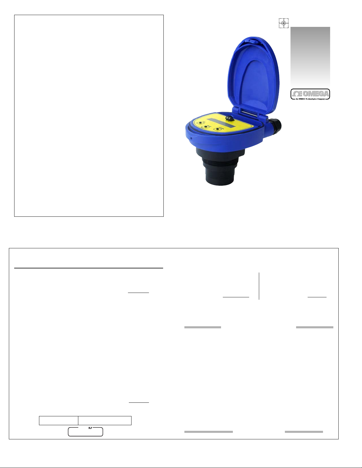
LVU800 Series
Ultrasonic Transmitter
WARRANTY/DISCLAIMER
OMEGA ENGINEERING, INC. warrants this unit to be free of defects in materials and workmanship for a
period of 13 months from date of purchase. OMEGA Warranty adds an additional one (1) month grace
period to the normal one (1) year product warranty to cover handling and shipping time. This ensures
that OMEGA’s customers receive maximum coverage on each product.
If the unit should malfunction, it must be returned to the factory for evaluation. OMEGA’s Customer Service
Department will issue an Authorized Return (AR) number immediately upon phone or written request. Upon
examination by OMEGA, if the unit is found to be defective it will be repaired or replaced at no charge.
OMEGA’s WARRANTY does not apply to defects resulting from any action of the purchaser, including but not
limited to mishandling, improper interfacing, operation outside of design limits, improper repair, or unautho-
rized modification. This WARRANTY is VOID if the unit shows evidence of having been tampered with or
shows evidence of being damaged as a result of excessive corrosion; or current, heat, moisture or vibration;
improper specification; misapplication; misuse or other operating conditions outside of OMEGA’s control.
Components which wear are not warranted, including but not limited to contact points, fuses, and triacs.
OMEGA is pleased to offer suggestions on the use of its various products. However, OMEGA neither
assumes responsibility for any omissions or errors nor assumes liability for any damages that result
from the use of its products in accordance with information provided by OMEGA, either verbal or writ-
ten. OMEGA warrants only that the parts manufactured by it will be as specified and free of defects.
OMEGA MAKES NO OTHER WARRANTIES OR REPRESENTATIONS OF ANY KIND WHATS0EVER,
EXPRESSED OR IMPLIED, EXCEPT THAT OF TITLE, AND ALL IMPLIED WARRANTIES INCLUDING ANY
WARRANTY OF MERCHANTABILITY AND FITNESS FOR A PARTICULAR PURPOSE ARE HEREBY DIS-
CLAIMED. LIMITATION OF LIABILITY: The remedies of purchaser set forth herein are exclusive and the
total liability of OMEGA with respect to this order, whether based on contract, warranty, negligence,
indemnification, strict liability or otherwise, shall not exceed the purchase price of the component
upon which liability is based. In no event shall OMEGA be liable for consequential, incidental or spe-
cial damages.
CONDITIONS: Equipment sold by OMEGA is not intended to be used, nor shall it be used: (1) as a “Basic
Component” under 10 CFR 21 (NRC), used in or with any nuclear installation or activity; or (2) in medical
applications or used on humans. Should any Product(s) be used in or with any nuclear installation or activity,
medical application, used on humans, or misused in any way, OMEGA assumes no responsibility as set forth
in our basic WARRANTY/ DISCLAIMER language, and additionally, purchaser will indemnify OMEGA and
hold OMEGA harmless from any liability or damage whatsoever arising out of the use of the Product(s) in
such a manner.
RETURN REQUESTS / INQUIRIES
Direct all warranty and repair requests/inquiries to the OMEGA Customer Service Department. BEFORE
RETURNING ANY PRODUCT(S) TO OMEGA, PURCHASER MUST OBTAIN AN AUTHORIZED RETURN (AR)
NUMBER FROM OMEGA’S CUSTOMER SERVICE DEPARTMENT (IN ORDER TO AVOID PROCESSING
DELAYS). The assigned AR number should then be marked on the outside of the return package and on
any correspondence.
The purchaser is responsible for shipping charges, freight, insurance and proper packaging to prevent
breakage in transit.
FOR WARRANTY
RETURNS, please have the fol-
lowing information available BEFORE contacting
OMEGA:
1. P.O. number under which the product
was PURCHASED,
2. Model and serial number of the product under
warranty, and
3. Repair instructions and/or specific
problems relative to the product.
FOR NON-WARRANTY REPAIRS,
consult OMEGA
for current repair charges. Have the following
information available BEFORE contacting OMEGA:
1. P.O. number to cover the COST
of the repair,
2. Model and serial number of product, and
3. Repair instructions and/or specific
problems relative to the product.
OMEGA’s policy is to make running changes, not model changes, whenever an improvement is possible.
This affords our customers the latest in technology and engineering.
OMEGA is a registered trademark of OMEGA ENGINEERING, INC.
© Copyright 1996 OMEGA ENGINEERING, INC. All rights reserved. This document may not be copied,
photocopied, reproduced, translated, or reduced to any electronic medium or machine-readable form, in whole or in part, without prior
written consent of OMEGA ENGINEERING, INC.
Servicing North America:
USA: One Omega Drive, Box 4047
ISO 9001 Certified Stamford, CT 06907-0047
Tel: (203) 359-1660
Fax: (203) 359-7700
e-mail: infor@omega.com
Canada: 976 Bergar
Laval (Quebec) H7L 5A1
Tel: (514) 856-6928
FAX: (514) 856-6886
email: canada@omega.ca
For immediate technical or application assistance:
USA and Canada: Sales Service: 1-800-826-6342 / 1-800-TC-OMEGA
SM
Customer Service: 1-800-622-2378 / 1-800-622-BEST
SM
Engineering Service: 1-800-872-9436 / 1-800-USA-WHEN
SM
Mexico En Espanol: (001) 203-359-7803
e-mail: espanol@omega.com
FAX: (001) 203-359-7807
info@omega.mx
Servicing Europe:
Czech Republic: Frystatska 184, 733 01 Karvina, Czech Republic
Tel: +420 (0)59 6311899
FAX: +420 (0)59 6311114
Toll Free: 0800-1-66342
e-mail: info@omegashop.cz
Germany/Austria: Daimlerstrasse 26, D-75392 Deckenpfronn, Germany
Tel: +49 (0)7056 9398-0
FAX: +49 (0)7056 9398-29
Toll Free in Germany: 0800 639 7678
e-mail: info@omega.de
United Kingdom: One Omega Drive, River BendTechnology Centre
ISO 9002 Certified Northbank, Irlam, Manchester
M44 5EX, England
Tel: +44 (0)161 777-6611
FAX: +44 (0)161 777-6622
Toll Free in England: 0800-488-488
e-mail: sales@omega.co.uk
omega.com
OMEGAnet
SM
On-Line Service Internet e-mail
http://www.omega.com info@omega.com
It is the policy of OMEGA to comply with all worldwide safety and EMC/EMI regulations that apply. OMEGA is constantly
pursuing certification of its products to the European New Approach Directives. OMEGA will add the CE mark to every
appropriate device upon certification.
The information contained in this document is believed to be correct but OMEGA Engineering, Inc. accepts no liability for any errors it con-
tains, and reserves the right to alter specifications without notice.
WARNING: These products are not designed for use in, and should not be used for, patient connected applications.
Where Do I Find Everything I Need for
Process Measurement and Control?
OMEGA…Of Course!
Shop online at omega.com
TEMPERATURE
Thermocouple, RTD & Thermistor Probes,
Connectors, Panels & Assemblies
Wire: Thermocouple, RTD & Thermistor
Calibrators & Ice Point References
Recorders, Controllers & Process Monitors
Infrared Pyrometers
PRESSURE, STRAIN AND FORCE
Transducers & Strain Gauges
Load Cells & Pressure Gauges
Displacement Transducers
Instrumentation & Accessories
FLOW/LEVEL
Rotameters, Gas Mass Flowmeters & Flow Computers
Air Velocity Indicators
Turbine/Paddlewheel Systems
Totalizers & Batch Controllers
pH/CONDUCTIVITY
pH Electrodes, Testers & Accessories
Benchtop/Laboratory Meters
Controllers, Calibrators, Simulators & Pumps
Industrial pH & Conductivity Equipment
DATA ACQUISITION
Data Acquisition & Engineering Software
Communications-Based Acquisition Systems
Plug-in Cards for Apple, IBM & Compatibles
Datalogging Systems
Recorders, Printers & Plotters
HEATERS
Heating Cable
Cartridge & Strip Heaters
Immersion & Band Heaters
Flexible Heaters
Laboratory Heaters
ENVIRONMENTAL
MONITORING AND CONTROL
Metering & Control Instrumentation
Refractometers
Pumps & Tubing
Air, Soil & Water Monitors
Industrial Water & Wastewater Treatment
pH, Conductivity & Dissolved Oxygen Instruments
M-4463/0707
OMEGA
®
TM
Page 2
Step One
SPECIFICATIONS
40
30
20
10
00
-40 -20 00 20 40 60 80
Acceptable
Range
Unacceptable
Range
Temperature/Pressure Derating
Operating Pressure (psi)
Temperature ( C)
12 16 20 24 28
Unacceptable
Range
Maximum Loop Resistance
Max. Series Resistance (Ohms)
Supply Voltage (VDC)
1,000
800
600
400
200
000
- Enhanced
Performance
- Specified
Performance
- Limited
Performance
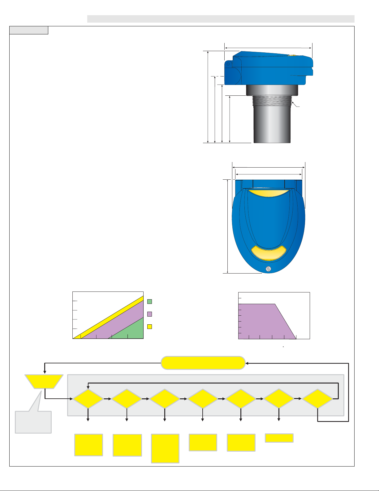
4.1"
(104 mm)
5.2"
(133 mm)
3.8"
(96 mm)
3.4"
(88 mm)
5.5"
(138 mm)
5.2"
(133 mm)
4.0"
(100 mm)
2.7"
(69 mm)
2" NPT
(2" G)
T op View
Range: LVU816: 8” to 16.4’ (10 cm to 5 m)
LVU826: 8” to 26.2’ (20 cm to 8 m)
LVU832: 12” to 32.8’ (30 cm to 10 m)
Accuracy: +/- 0.2% of span in air
Resolution: LVU816: 0.039 (1 mm)
LVU826: 0.039 (1 mm)
LVU832: 0.078: (2 mm)
Beam width: 3” (7.6cm) dia.
Dead band LVU816: 8” (10cm)
LVU826: 8” (20cm)
LVU832: 12” (30cm)
Display type: LCD, 6-digit
Display units: Inch, cm or percentage
Display mode: Air gap or liquid height
Memory: Non-volatile
Supply voltage: 12- 28 VDC
Loop resist,: 500 Ohms @ 24 VDC
Signal output: 4 - 20 mA, two -wire
Signal invert: 4-20 mA, 20-4 mA
Calibration: Push button
Fail-safety: Selectable: 4 mA, 20 mA, 21 mA,
22 mA or hold last value
Process temp.: F: -4° to 140°
C: -20° to 60°
Temp comp,: Automatic
Electronics temp.: F: -40° to 160°
C: -40° to 71°
Pressure: 30 psi (2 bar) @ 25 °C., derated @
1.667 psi (113 bar) per °C, above 25 °C
Enclosure rating: NEMA 4X (IP65)
Enclosure vent: Water tight membrane
Encl. material: PC/ABS FR
Trans. material: PVDF
Process mount: 2” NPT (2” G)
Mount. gasket: Viton®
Conduit entrance: Dual, 1/2” NPT
Classification: General purpose
CE compliance: EN 61326 EMC
SELECT / FAST
Button
DISPLAY
UNITS TANK SAFE TGCAL VALUES RUN
TOP MENU
Inches
Centimeters
Percentage
Display
Height (4 mA)
Fill H (20 mA)
Rev mA
Help
22 mA
21 mA
20 mA
4 mA
Hold
FULL
EMPTY
Help
To activate the top
menu, press and
hold SELECT / FAST
button for 5 seconds
SELECT
Display Units
SELECT
4-20 Span
SELECT
Fail-Safety
SELECT
Target-Cal
SELECT
Diagnostics
Setup
Diagnostics
Reset
HELP
SELECT
Diagnostics
Contact
Side View
Page 3
Step Tw o
SAFETY
Step Three
OVERVIEW
A. Application: The general-purpose ultrasonic transmitter pro-
vides non-contact level detection up to 32.8’ or 10m. The transmitter
is well suited for a wide range of corrosive, waste and slurry type
media, and is broadly selected for atmospheric bulk storage, day tank
and waste sump applications.
B. Part Number: The part and serial numbers are located on the
wrench flat. Check the part number on the product label and confirm
which of the below model configurations you have purchased:
Par
t Number Range Supply Mount
LVU816 16.4’ (5 m) 12-28 VDC 2” NPT
LVU816G 16.4’(5 m) 12-28 VDC 2” G
LVU826 26.2’ (8 m) 12-28 VDC 2” NPT
LVU826G 26.2’(8 m) 12-28 VDC 2” G
LVU832 32.2’ (10 m) 12-28 VDC 2” NPT
LVU832G 32.2’(10 m) 12-28 VDC 2” G
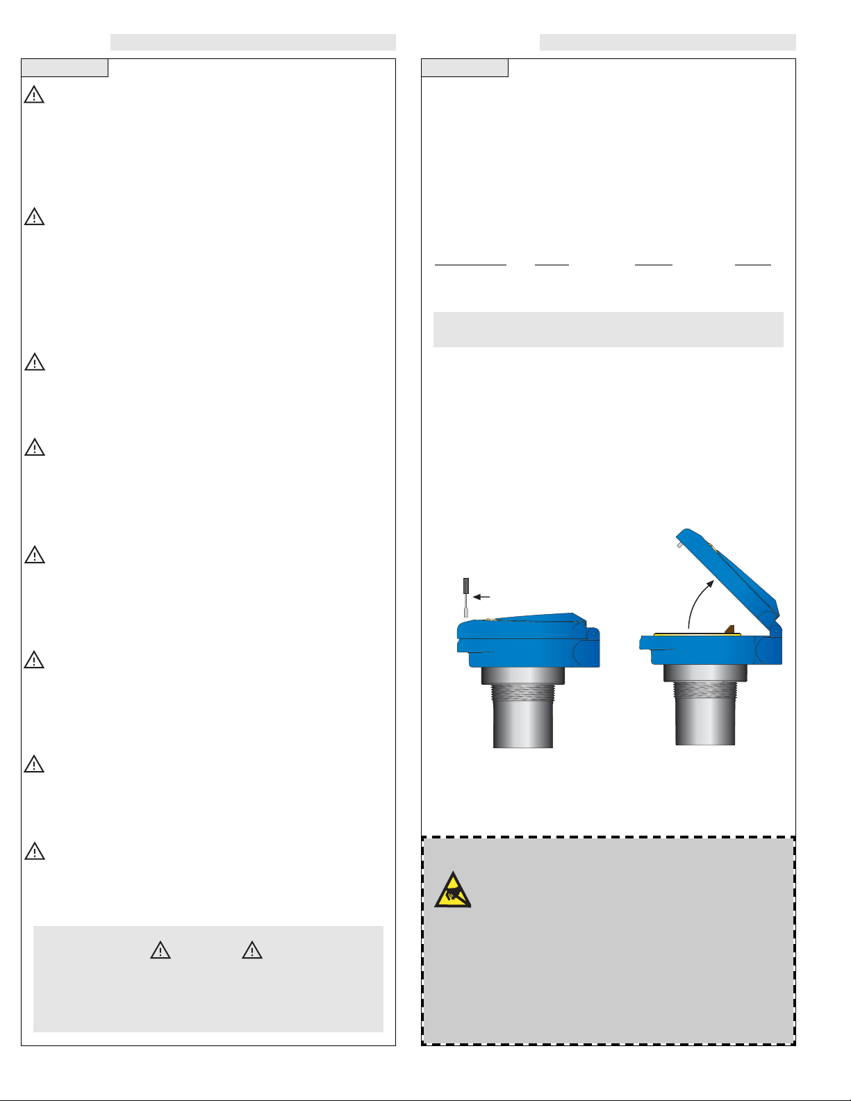
C. NEMA 4X Enclosure: The NEMA 4X (IP65) enclosure has
a flip cover with two 1/2” NPT female conduit ports and an internal
terminal strip for wiring. T o open the enclosure, you will need a small
small screwdriver. Insert the tool into the hole located at the top edge
of the enclosure and turn counter-clockwide. Rotate the hinged cover
up for 135° access to the faceplate screen and terminal strip.
About this Manual: PLEASE READ THE ENTIRE MANU-
AL PRIOR TO INSTALLING OR USING THIS PRODUCT. This
manual includes information on then LVU800 Ultrasonic Level
Transmitter from OMEGA. Please refer to the part number located
on the transmitter label to verify the exact model configuration
which you have purchased.
User’s Responsibility for Safety: OMEGA manufactures
a broad range of level sensing technologies. While each of these
sensors is designed to operate in a wide variety of applications, it is
the user’s responsibility to select a sensor model that is appropriate
for the application, install it properly, perform tests of the installed
system, and maintain all components. The failure to do so could
result in property damage or serious injury.
Proper Installation and Handling: Only properly trained
staff should install and/or repair this product. Install the transmitter
with the Viton gasket and never overtighten the transmitter within
the fitting. Always check for leaks prior to system start-up.
Wiring and Electrical: A supply voltage (loop power) of 12
-28 VDC is used to power the LVU800 series. The sensor circuit
should never exceed a maximum of 28 volts DC. Electrical wiring
of the sensor should be performed in accordance with all applicable national, state, and local codes.
Material Compatibility: The LVU800 series enclosure is
made of a flame retardant Polycarbonate (PC/ABS FR). The transducer is made of Polyvinylidene Fluoride (PVDF). Make sure that
the model which you have selected is chemically compatible with
the application media and it’s environment.
Enclosure: While the transmitter housing is liquid-resistant the
LVU800 series is not designed to be operational when immersed. It
should be mounted in such a way that the enclosure and transducer do not come into contact with the application media under normal operational conditions.
Make a Fail-Safe System: Design a fail-safe system that
accommodates the possibility of transmitter and/or power failure.
OMEGA recommends the use of redundant backup systems and
alarms in addition to the primary system.
Flammable, Explosive or Hazardous Applications:
Do not use the L VU800 seriesof general purpose transmitters within classified hazardous environments.
Warning
Always use the Viton gasket when installing the LVU800 series
transmitter in its fitting, and always connect the shield wire to
the common ground.
Handling Static-Sensitive Circuits/Devices
When handling the transmitter, the technician should follow
these guidelines to reduce any possible electrostatic charge
build-up on the technicians body and the electronic part.
1. Always touch a known good ground source before handling the
part. This should be repeated while handling the part and more
frequently after sitting down from a standing position, sliding
across the seat or walking a distance.
2. Avoid touching electrical terminals of the part unless making connections.
3. DO NOT open the unit cover until it is time to calibrate.
Before closing the enclosure, make sure that the enclosure gasket is
properly seated, and that any conduit fittings, liquid tight cable connectors and/or plugs are properly installed and sealed.
Closed
Open
Page 4

Step Four
PREPARATION
A. Supply V oltage: The transmitter power supply voltage should
never exceed a maximum of 28 VDC. Omega controllers and meters
have built-in 24 VDC power supplies for use with the transmitter.
Alternative controllers and/or power supplies with a minimum output
of 12 VDC may also be used with the transmitter for calibration
and/or operation.
B. Cable Length: The cable length between the transmitter and
it’s point of termination may be extended up to a maximum of 1000
feet, using a well-insulated, shielded wire from 14 to 18 gauge.
C. Factory Span: All transmit-
ter models are factory calibrated with
4 mA at their maximum range (tank
empty) and 20 mA at their minimum
range (tank full). The 4 and 20 mA
span set points can be reverse calibrated on all models.
D.Maximum Applied Range:
The Individual or cumulative effects
of agitation, vapor or foam can
reduce the overall quality of signal
return and shorten the maximum
applied range of the transmitter. To determine the maximum applied
range of the transmitter in your application, refer to the below derating chart.
0
Maximum Applied Range Derating Chart
LVU800
Agitation = 1-3 @ 50 kHz
Vapor = 3-5 @ 50 kHz
Foam = 4-6 @ 50 kHz
Step Five
MENU ITEMS
A. WARMUP: This is the initial power up mode. When this mes-
sage is displayed, the transmitter is going through its power up routine, and validating the target value. After a short period of time, this
message will disappear and be replaced by a numeric value.
B. FULL: Level has reached the programmed FULL set point.
C. EMPTY: Level has reached the programmed EMPTY set point
D. UNITS: Selectable in Inches Centimeters or Percent. The facto-
ry default is Inches.
E. INCHES: Inch units of measurement.
F. CM: Centimeters units of measurement.
G. PERCNT: 0-100% units of measurement. Percent is the calcu-
lated value based on the 4mA and 20mA set points.
H. DISPLAY: Allows the user to select if the display will read in
units of air or units of liquid. Factory default is units of air.
H.TANK: Menu through which the 4-20 mA span is adjusted.
I. HEIGHT: The point in inches
or centimeters from the transducer
face where the output will be 4 mA
(generally the bottom of the tank).
Factory default is the same as the
unit’s maximum range. Example:
LVU816 = 197” maximum range
which is also the same 4 mA set
point under factory default.
J. Fill H (Fill Height): The
point in inches or centimeters from
the bottom of the tank to the high
level where the output will be 20
mA(generally the straight wall distance from the bottom of the tank).
NOTE: The transmitter dead band
is automatically subtracted from
the FILL H. Example: LVU816 =
8” dead band. Therefore the maximum FILL H is 197” [maximum
range] - 8” [dead band] = 189”.
K. REV mA (Reverse mA): Allows the user to select 20 mA at
the bottom and 4 mAat the top of the tank (20-4 mA). Factory default
is 4 mA (MaxR) at the bottom and 20 mA (MinR) at the top.
L. SAFE: The FAIL-SAFE current output of the transmitter if the
acoustic signal is LOST. Selectable at 4 mA, 20 mA, 21 mA, 22 mA
or HOLD. (HOLD is the last 4-20 mA value prior to LOST).
M.TG CAL:Allows the user to use an unknown distance for setting
of the 4 mA and 20 mA span.
HEIGHT
(MaxR)
FILL H
(MinR)
EMPTY
FULL
LVU800 Series
Reverse Mode
4 mA
20 mA
0%
50%
100%
01234567891
50Khz
Page 5

Step Six
MENU ITEMS
Step Seven
PROGRAMMING
A. Introduction: The transmitter has two modes, RUN and PRO-
GRAM. In the RUN mode, the transmitter is operational and the display will indicate the liquid height in inches, centimeters or percent.
In the PROGRAM mode, the display will indicate the selected mode
of calibration. The transmitter arrives from the factory with its settings at 4 mA = maximum range and 20 mA = minimum range
(defined by the dead band or minimum measurement distance). The
transmitter is programmed with it’s built-in display and three button
keyboard. Under normal application circumstances, users typical-
ly program the HEIGHT distance value, FILL H distance value
and FAIL-SAFE mode.
+
UP DOWN
SELECT
FAST
--
+
UP DOWN
SELECT
FAST
--
Hold for
5 Seconds
Top Menu
B. Entering the Program Mode: Press and hold the
SELECT/FAST button for approximately 5 seconds until the display
changes from a numeric value to PROG, indicating that you have
entered the PROG mode.
Note: When PROG mode is active, the sensor will hold the last
current value. The value will not change until the transmitter is
returned to RUN Mode.
After entering the PROG mode, the display will scroll through the top
menu, alternately flashing UNITS, TANK, SAFE, TG CAL, VALUES, HELP and RUN.
N. FULL: Target calibration technique that allows the user to enter
the present distance from the transducer face to the liquid or a reflective target as the 20 mA (FULL) set point
O. EMPTY: Target calibration technique that allows the user to
enter the present distance from the transducer face to the liquid or a
reflective target as the 4 mA (EMPTY) set point.
P. WAIT: Indicates that you have selected either FULL or EMPTY
and the transmitter is calculating the distance value.
Q.VALUES: Allow the user to view the present calibration settings
that are programmed in the transmitter.
R. SETUP: Displays the present calibration settings such as UNITS,
MinR, MaxR, and SAFE.
S. MINR: The lesser distance from the transducer to the full tank
height of liquid.
T. MAXR: The greater distance from the transducer to the empty tank
height of liquid.
U. RESET: Allows the user to reset the transmitter to its original
factory default settings.
V. DIAG (Diagnostics):Allows the user to view the present val-
ues of LEVEL, TEMP, ECHO, POWER, MOUNT and VER.
W. LEVEL: Displays the current Inch, Centimeter or Percent mea-
sured value.
X.TEMP: Displays the temperature in the vessel at the transducer.
Y. ECHO: Displays the present acoustic signal strength.
Z. POWER: Displays the present acoustic power level
AA. MOUNT: Displays either QUIET (no fitting noise) or NOISY
(potential fitting noise), If NOISY with transmitter performance
issues, please contact Omega to discuss your installation.
BB.VER (VERSION): Displays the transmitter software version.
CC. DONE: Indicates that the new value has been saved in memo-
ry (after depressing the SELECT/FAST key).
DD. ERROR: Indicates that the new value has NOT been saved in
memory (after depressing the SELECT/FAST or EXIT key).
EE. RUN: When displayed, if the user depresses the
SELECT/FAST key, the transmitter will exit the programming mode
and return to the RUN mode for normal operation.
FF. UP / DOWN:Increases or decreases the SET20 and SET 4 dis-
play values in the programming mode. NOTE: Simultaneously holding down the SELECT/FASTbutton while pressing the UP or DOWN
button will increase the speed of the display.
Page 6

Step NineStep Eight
PROGRAMMING
C. Programming UNITS: To change UNITS from INCHES to
CM or PERCENT.
1. Press the SELECT/FAST button and hold it for 5 seconds until
PROG appears.
2. When UNITS appears, press the SELECT/FAST button. The display
will rotate between INCHES, CM, PERCENT and DISPLAY.
3. Press the SELECT/FAST button when the UNITS you want
(INCHES, CM or PERCENT) appear. The display will then display SAVED.
You have successfully changed the UNITS function.
Note: Percent units can only be selected after the transmitters Height (4 mA) and Fill H (20 mA) set points have
been programmed. Therefore initial programming should
always be done in INCH or CM UNITS.
D. Display Mode: The transmitter is factory set such that the
display reads the distance from the bottom of the transmitter to
the liquid surface. This is also referred to as the Air distance (Air
Mode). As the level of liquid increases, the display will decrease
and vice versa. Conversely, the transmitter may be set to read the
actual height of liquid in the tank (Liquid Mode). Below, a tank
height of 100” will display 40.0, which represents 40.0” of air in
the AIR Mode. In the Liquid Mode, the display will change to
60.0, which represents 60.0” of liquid.
AIR MODE LIQUID MODE
PROGRAMMING
SELECT
FAST
SELECT
FAST
HEIGHT
(MaxR)
FILL H
(MinR)
E. Change Display Mode: To change the display to indicate
the height of liquid, follow the instructions below:
1. Press the SELECT/FAST button and hold it for 5 seconds until
PROG appears.
2. When UNITS appears, press the SELECT/FAST button. The display will rotate between INCHES, CM, PERCENT and DISPLAY.
3. When DISPLAY appears, press the SELECT/FAST button. The
display will rotate between AIR or LIQUID.
4. When LIQUID appears, press the SELECT/FAST button.
You have successfully programmed the LIQUID mode.
F .Programming Off Tank: If you know the dimensions of your
tank, you may input the 4 mA and 20 mAset points manually without
performing target calibration (requiring you to raise and lower the liquid level). To do so, review the following:
HEIGHT: The point in inches or centimeters from the transducer
face where the output will be 4 mA (generally the bottom of the
tank). Factory default is the same as the unit’s maximum range.
Example LVU816 = 197” maximum range which is also the same
4 mA set point under factory default.
FILL H:The point in inches or centimeters from the bottom of the
tank to the high level where the output will be 20 mA(generally the
straight wall distance from the bottom of the tank). NOTE: The
transmitter dead band is automatically subtracted from the FILL H.
Example: LVU816 = 8” dead band. Therefore the maximum FILL
H is 197” [maximum range] - 8” [dead band] = 189”.
40.0" of Air
100.0"
Height
60.0" of Liquid
100.0"
Height
SELECT
FAST
SELECT
FAST
SELECT
FAST
Page 7

Step Ten Step Eleven
PROGRAMMING
I. Programming REV mA (Optional): In factory default, the
transmitter operates with 4 mA at the maximum range (MaxR), and
20 mA at the dead band (MinR). Using the menu item REV mA, you
can change the unit to reverse this to 20 mA at the furthest distance
(MaxR) and 4 mA at the closest distance (MinR).
NOTE: You must set HEIGHT and FULL R prior to reversing
the 4 and 20 mA. Regardless of which mode you are in (Norm
or Rev), changes to the HEIGHT or FULL R are always with
respect to the original settings programmed.
NOTE: Any changes to the HEIGHT will effect the FULL R
value. The FULL R will stay at the same physical level in the
tank. An increase to the HEIGHT value will result in an equal
increase to the FULL R value. A decrease to the HEIGHT value
will result in an equal decrease to the FULL R value.
4 mA
20 mA
SELECT
FAST
SELECT
FAST
SELECT
FAST
20 mA
4 mA
Normal mA Mode
MaxR (4 mA) set at empty tank
and MinR (20 mA) set at full tank.
Reverse mA Mode
MaxR (20 mA) set at empty tank
and MinR (4 mA) set at full tank.
PROGRAMMING
G. Programming HEIGHT: To change HEIGHT 4 mA value.
1. Press the SELECT/FAST button and hold it for 5 seconds until
PROG appears.
2. When TANK appears, press the SELECT/FAST button. The display will rotate between HEIGHT, FILLH and REV mA.
3. When HEIGHT appears, press the SELECT/FAST button. The
display will show a decimal reading in the selected UNITS.
4. Press the UP/DOWN buttons to increase or decrease this value to the
distance from the transducer face to the bottom of the tank. NOTE:
Simultaneously holding down the SELECT/F ASTbutton while pressing the UP or DOWN button will increase the speed of the display.
5. When you have reached the desired value, press SELECT/FAST
to SAVE.
You have successfully programmed the HEIGHT or 4 mA value.
H. Programming FILL H: To change FILL H 20 mA value.
1. Press the SELECT/FAST button and hold it for 5 seconds until
PROG appears.
2. When TANK appears, press the SELECT/FAST button. The display will rotate between HEIGHT, FILLH and REV mA.
3. When FULL H appears, press the SELECT/F ASTbutton. The display will show a decimal reading in the selected UNITS.
4. Press the UP/DOWN buttons to increase or decrease this value to
the distance from the bottom of the vessel to the full point (typically the straight wall height).
5. When you have reached the desired value, press SELECT/FAST
to SAVE it.
You have successfully programmed the FILL H or 20mA value.
NOTE: You can increase the speed at which the display changes
by pressing the SELECT/FAST button while simultaneously holding down the UP or DOWN button.
SELECT
FAST
SELECT
FAST
SELECT
FAST
UP
DOWN
SELECT
FAST
SELECT
FAST
SELECT
FAST
UP
DOWN
Page 8

Step ThirteenStep Twelve
L. Programming TG CAL EMPTY Tank: With the tank
EMPTY or the liquid in a low level state, apply power to the transmitter. Begin programming after WARMUP.
1. Press the SELECT/FAST button and hold it for 5 seconds until
PROG appears.
2. When TG CAL appears, press the SELECT/FAST button. The
display will rotate between FULL and EMPTY.
3. When EMPTY appears, press the SELECT/FAST button. WAIT
will be displayed followed by SAVED.
You have successfully programmed the EMPTY or 4 mA value.
M. Programming TG CAL FULL Tank:With the tank FULL,
or the liquid in a high level state, apply power to the transmitter.
Begin programming after WARMUP.
1. Press the SELECT/FAST button and hold it for 5 seconds until
PROG appears.
2. When TGCAL appears, press the SELECT/F ASTbutton. The display will rotate between FULL and EMPTY.
3. When FULL appears, press the SELECT/F ASTbutton, W AITwill
be displayed followed by SAVED.
You have successfully programmed the FULL or 20 mA value.
PROGRAMMING
SELECT
FAST
SELECT
FAST
SELECT
FAST
SELECT
FAST
SELECT
FAST
SELECT
FAST
Note: The display will now indicate LEVEL height in the RUN
mode.
J. Programming SAFE Mode: To change SAFE mode.
1. Press the SELECT/FAST button and hold it for 5 seconds until
PROG appears.
2. When SAFE appears, press the SELECT/FAST button.
3. The display will now rotate through 22mA, 21mA, 20mA, 4mA
and HOLD. When you reach the desired setting, press the
SELECT/FAST button to SAVE it..
You have successfully programmed the SAFE mode.
K. Programming Target Calibration (Optional): The
transmitter’s 4 mA and 20 mA set points can be target calibrated ON
the tank by raising and lowering the liquid level, or OFF the tank
using the distance to a flat reflective target such as a wall. Generally,
target calibration is done ON the tank. To do so, follow the EMPTY
and FULL tank programming steps on the next page.
NOTE: A transmitter installed on a tank operating in the factory default RUN mode will display the distance from the bottom
of the sensor to the liquid surface. The value will decrease as the
tank is filled or increase as the tank is emptied. Make sure that
you do not overflow the tank or completely empty the tank while
moving the liquid level to the desired high or low set point distance for target calibration.
TG CAL:Allows the user to use an unknown distance for setting
of the 4 mA and 20 mA span.
FULL: Target calibration technique that allows the user to enter
the present distance from the
transducer face to the liquid or a
reflective target as the 20 mA
(FULL) set point
EMPTY: Target calibration
technique that allows the user to
enter the present distance from
the transducer face to the liquid
or a reflective target as the 4 mA
(EMPTY) set point.
SELECT
FAST
SELECT
FAST
EMPTY
FULL
PROGRAMMING
Page 9
Step FifteenStep Fourteen
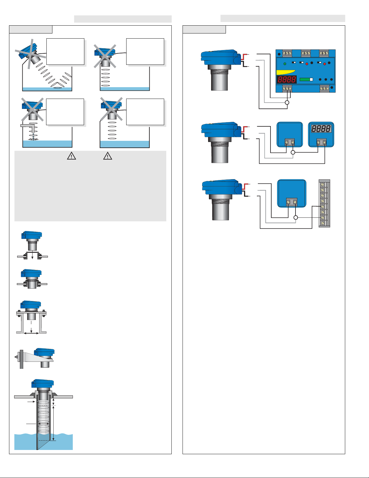
C.Wiring to a Typical Programmable Logic Controller
- ++ -
DC Power
Supply
12-28 VDC
(+)
(-)
SHIELD
+ -
DC Power
Supply
12-28 VDC
TYpical PLC
6
5
4
3
2
1
0
A
(+)
(-)
Shield
WIRING
A.Wiring to a Omega LVCN-51 Controller
B.Wiring to a Typical Two-Wire Loop Powered Indicator
LATCH
ON OFF
PWR
RELAY 1
INVERT
DELAY
RELAY 2
INVERT
DELAY
4 20 OP
EASY CAL
UP DOWN SET
INPUT
0% 100%
OFF SET
SPAN
RLY1
RLY2A
RLY2B
(+)
(-)
SHIELD
JWA mode
A. Fitting Selection: Check the transmitter
part number to determine the required 2” fitting
thread type. The transmitter is commonly installed
in tank adapters, flanges, brackets or stand pipes.
1. Adapter: Select a tank adapter fitting with
minimal height so as to ensure that the
installed transducer will not be substantially
elevated into the fitting. Avoid tank adapter
styles with threads and/or pipe stops forward
of the installed transducer.
2. Flange: Tall flanges with narrow risers
impede the acoustic signal. Select a fitting
with the right riser height versus inner diameter geometry. The transmitter may be elevated up to 12” (30 cm) in a 6” (15 cm) riser, 8”
(20 cm) in a 4” (10 cm) riser and 3” (7.6 cm)
in a 2” (5 cm) riser.
3. Bracket: The LVM-30 bracket or equivalent
can be used for open tank top installations
against the side wall.
4. Stand Pipe: A stand pipe may be
used to dampen turbulence or separate
surface foam. Select a minimum 3” pipe
for the stand pipe. The pipe length
should run the measurement span. Cut a
45° notch at the bottom of the pipe and
drill a 1/4” pressure equalization hole
high in the dead band.
VACUUM
Do not install at
angle relative
to the liquid
Do not install
within 3” of
tank side wall
Do not install
with objects
in the beam
Do not install
in applications
with vacuum
Warning
Omega ultrasonic transmitters have been optimized for use in
non-metallic fittings. For best performance, avoid the use of
metal fittings.
Install the appropriate installation fitting. Make sure that the fitting and transmitter threads are not damaged or worn. Install the
transmitter with the included Viton mounting gasket. Hand tighten the transmitter within the fitting. Perform an installed leak test
under normal process conditions prior to system start up.
Adapter
Flange
Stand Pipe
Bracket
Gasket
Riser
INSTALLATION
Inner Diameter
Ventilation
Hole
3" Minimum
Diameter
Height
Dead Band
Highest
Liquid Level
Operational Range
Lowest
Liquid Level
Page 10

Step SeventeenStep Sixteen
C. Factory RESET:
1. Press the SELECT/FAST button and hold it for 5 seconds until
PROG appears.
2. When VALUES appears, press the SELECT/FAST button. The
display will rotate between SETUP, DIAG and RESET.
3. When RESET appears, press the SELECT/FAST button. The display will rotate between YES or NO.
4. When YES appears, press the SELECT/FAST button.
Note: FACTORY RESET resets the transmitter back to its original factory default settings: (20 mA = Minimum Range, 4mA =
Maximum Range and SAFE = 22mA).
D.Testing the Transmitter
1. Connect a multimeter in series
with the black wire to read the
current output.
2. Verify that the current increases (tank filling) and decreases
(tank emptying) appropriately
in the calibrated span.
3. If not, carefully observe and
attempt to correlate any installation, level or application
event for more specific troubleshooting.
4. Write down the information in
DIAGNOSTICS (LEVEL, TEMPECHO, POWER, MOUNT and
VER) and have it ready when you contact your Flowline representative.
SELECT
FAST
SELECT
FAST
SELECT
FAST
TROUBLESHOOTING
TROUBLESHOOTING
A.Viewing Programmed VALUES:
1. Press the SELECT/FAST button and hold it for 5 seconds until
PROG appears.
2. When VALUES appears, press the SELECT/FAST button. The
display will rotate between SETUP, DIAG and RESET.
3. When SETUP appears, press the SELECT/FAST button. You will
now begin viewing calibration settings (UNITS, Display, MinR,
MaxR and SAFE) that are programmed in the transmitter.
When complete the display will revert back to the VALUES menu.
B.Viewing DIAGNOSTICS:
1. Press the SELECT/FAST button and hold it for 5 seconds until
PROG appears.
2. When VALUES appears, press the SELECT/FAST button. The
display will rotate between SETUP, DIAG and RESET.
3. When DIAG appears, press the SELECT/FAST button. You will
now begin viewing diagnostic values (LEVEL, TEMP ECHO,
POWER, MOUNT and VER) that may be relevant to the transmitter and it’s performance in your application.
When complete the display will revert back to the VALUES menu.
SELECT
FAST
SELECT
FAST
SELECT
FAST
SELECT
FAST
SELECT
FAST
SELECT
FAST
Factory Set Points
Transmitter
LVU816
LVU826
LVU832
4 mA Setting
16.4’ (5m)
26.2’ (8m)
32.8’ (10m)
20 mA Setting
8” (10 cm)
8” (20 cm)
12” (30 cm)
Power
Supply
456
Power
Supply
mA
Red
Black
Red
Black
2
0 mA
4 mA
192021
mA
 Loading...